


Alle Rechte vorbehalten. Irrtümer und Änderungen vorbehalten.
1 Zu diesem Dokument
Dieses Dokument gilt für die Mehrstrahl-Sicherheits-Lichtschranke deTem2 Core A/P,
deT
em4 Core A/P.
2 Zu Ihrer Sicherheit
GEFAHR
Gefahr der Unwirksamkeit der Schutzeinrichtung
Der Gefahr bringende Zustand der Maschine wird bei Nichtbeachtung möglicherweise
nicht oder nicht rechtzeitig beendet.
b
Beachten Sie den beiliegenden Sicherheitshinweis.
Die Mehrstrahl-Sicherheits-Lichtschranke ist unter anderem für nachfolgende Verwen‐
dun
gen nicht geeignet:
•
Im Freien
•
Unter Wasser
•
In explosionsgefährdeten Bereichen
•
In Höhen über 3000 m ü. NHN
•
In Umgebungen mit erhöhter ionisierender Strahlung
Im isolierten 24-V-DC-Versorgungsstromkreis zum Gerät muss eine Sicherung mit
einem Nennstrom von maximal 4 A angebracht werden, um den verfügbaren Strom zu
begrenzen.
Weitere Informationen zur Arbeit mit der Schutzeinrichtung enthält die Maschinendoku‐
mentation oder die Betriebsanleitung der Schutzeinrichtung. Sie finden die EU-Konfor‐
mitätserklärung und die aktuelle Betriebsanleitung der Schutzeinrichtung, indem Sie
auf www.sick.com im Suchfeld die Artikelnummer eingeben (Artikelnummer: siehe
Typenschildeintrag im Feld „Ident. no.“).
3 Aktiv- und Passiv-Einheit
Das Symbol kennzeichnet die Aktiv-Einheit.
Das Symbol kennzeichnet die Passiv-Einheit.
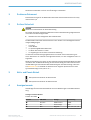
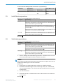
4 Anzeigeelemente
Vollständige Übersicht der LED-Zustände und ihrer Bedeutungen: siehe Betriebsanlei‐
t
ung.
Anzeigen der Aktiv-Einheit
Position der LEDs:
A
Position LED-Farbe Anzeige Beschriftung
!
Rot/Grün OSSD-Zustand OSSD
"
Rot Fehleranzeige ERR
§
Blau Diagnose 1, 2, 3, 4, 5, 6, 7, 8
MONTAGEANLEITUNG
8024797/2020-03-06 | SICK M O N T A G E A N L E I T U N G | deTem2 Core A/P, deTem4 Core A/P
3
Irrtümer und Änderungen vorbehalten

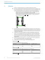
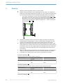
5 Montieren
b
Die Ak
tiv- und Passiv-Einheit auf einem planen Untergrund montieren.
b
Die Aktiv- und Passiv-Einheit rechtwinklig zueinander ausrichten. Die Optiken müs‐
sen sich gegenüberliegen. Für kleinere Korrekturen bei der Ausrichtung lassen sich
die Aktiv- und Passiv-Einheit in den Halterungen in Längsrichtung verschieben.
°
Bei Passiv-Einheit für kleine Reichweiten: Die Aktiv- und Passiv-Einheit auf
gleicher Höhe montieren, siehe Maßzeichnungen
B und C .
°
Bei P
assiv-Einheit für große Reichweiten: Die Passiv-Einheit vertikal versetzt
zur Aktiv-Einheit montieren. Dabei den Abstand A = 71,8 mm berücksichti‐
gen, siehe Maßzeichnungen
B und D .
90˚
9
0˚
A
b
Die H
alterungen in der Nähe der Gehäuseenden positionieren. Wenn das Gerät im
Betrieb starken Vibrationen ausgesetzt ist, die Montagehöhe der oberen Halterung
so wählen, dass der Absatz im Gehäuse der Mehrstrahl-Sicherheits-Lichtschranke
auf der Halterung aufsitzt.
b
Anzugsdrehmoment für die Schrauben, mit denen die Halterung montiert wird:
5 Nm … 6 Nm. Anzugsdrehmoment für die Schrauben, mit denen die Mehrstrahl-
Sicherheits-Lichtschranke in der Halterung fixiert wird: 2,5 Nm … 3 Nm. Höhere
Drehmomente können die Halterung beschädigen, geringere Drehmomente bieten
keine ausreichende Sicherheit gegen ein Verschieben der Mehrstrahl-Sicherheits-
Lichtschranke.
b
Auf die korrekte Ausrichtung der Aktiv- und Passiv-Einheit achten. Die Optiken der
Aktiv- und Passiv-Einheit müssen sich gegenüberliegen.
b
Parallelität der Komponenten ggf. mit einer Wasserwaage prüfen.
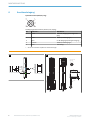
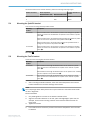
Maßzeichnung:
B
V
on der Strahlanzahl abhängige Maße, Aktiv-Einheit
Strahlanzahl Strahlabstand, Maß S in mm Länge, Maß L in mm
2 500 672
4 300 1072
Maßzeichnung: C
V
on der Strahlanzahl abhängige Maße, Passiv-Einheit für kleine Reichweite
Strahlanzahl Strahlabstand, Maß S in mm Länge, Maß L in mm
2 500 672
4 300 1072
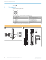
Maßzeichnung: D
MONTAGEANLEITUNG
4
M O N T A G E A N L E I T U N G | deTem2 Core A/P, deTem4 Core A/P 8024797/2020-03-06 | SICK
Irrtümer und Änderungen vorbehalten

Von der Strahlanzahl abhängige Maße, Passiv-Einheit für große Reichweite
Strahlanzahl Strahlabstand Länge, Maß L in mm
Maß S1 in mm Maß S2 in mm
2 500 - 528,4
4 - 300 928,4
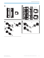
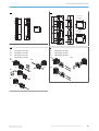
5.1 QuickFix-Halterung montieren
Seitliche und rückseitige Montage der QuickFix-Halterung
Montageart Beschreibung
Seitlich Mit der M5-Schraube durch die QuickFix-Halterung an den Maschinen- oder
Pr
ofilrahmen. Am Maschinen- oder Profilrahmen ist eine Schraubenmutter
oder eine Gewindebohrung erforderlich (!).
Mit der M5-Schraube durch den Maschinen- oder Profilrahmen an die
Q
uickFix-Halterung. Eine Schraubenmutter ist für jede QuickFix-Halterung
erforderlich (").
Mit der M5-Schraube durch die QuickFix-Halterung an den Profilrahmen. Am
Pr
ofilrahmen ist ein Nutenstein erforderlich (§).
Rückseitig Mit der M5-Schraube durch die QuickFix-Halterung an den Maschinen- oder
Pr
ofilrahmen. Am Maschinen- oder Profilrahmen ist eine Schraubenmutter
oder eine Gewindebohrung erforderlich ($).
Montage: E
5.2 FlexFix-Halterung montieren
Seitliche und rückseitige Montage der FlexFix-Halterung
Montageart Beschreibung
Seitlich Mit der M5-Schraube durch die FlexFix-Halterung an den Maschinen- oder
Profilrahmen. Am Maschinen- oder Profilrahmen ist eine Schraubenmutter
oder eine Gewindebohrung erforderlich (!).
Mit der M5-Schraube durch die FlexFix-Halterung an den Profilrahmen. Am
Pr
ofilrahmen sind 2 Nutensteine erforderlich (").
Rückseitig Mit der M5-Schraube durch die FlexFix-Halterung an den Maschinen- oder
Pr
ofilrahmen. Am Maschinen- oder Profilrahmen ist eine Schraubenmutter
oder eine Gewindebohrung erforderlich (§).
1. Nach der Montage der FlexFix-Halterungen die Aktiv- und Passiv-Einheit von vorne
in die F
lexFix-Halterungen eindrehen und jeweils ausrichten.
HINWEIS
D
as Eindrehen der Mehrstrahl-Sicherheits-Lichtschranke ist nur möglich, wenn sich die
beiden FlexFix-Halterungen in einer Flucht befinden.
Empfehlung:
1. Die Schrauben der FlexFix-Halterungen zunächst nur handfest eindrehen.
2. Die beiden FlexFix-Halterungen in eine Flucht bringen. Dazu z. B. ein Richtscheit
oder eine Wasserwaage an die nicht benutzten Anschraubflächen der FlexFix-Hal‐
terungen legen.
3. Schrauben festdrehen.
2. Die Position der Aktiv- und Passiv-Einheit mit der M5-Schraube in der FlexFix-Hal‐
t
erung fixieren.
Montage:
F
MONTAGEANLEITUNG
8024797/2020-03-06 | SICK M O N T A G E A N L E I T U N G | deTem2 Core A/P, deTem4 Core A/P
5
Irrtümer und Änderungen vorbehalten

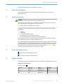
6 Anschlussbelegung
Systemanschluss (M12, 5-polig)
12
3
4
5
Pinbelegung Systemanschluss (Stecker, M12, 5-polig)
Pin Aderfarbe
1)
Aktiv-Einheit
1 Braun +24 V DC (Eingang Spannungsversor‐
gun
g)
2 Weiß OSSD1 (Schaltausgang 1)
3 Blau 0 V DC (Eingang Spannungsversorgung)
4 Schwarz OSSD2 (Schaltausgang 2)
5 Grau Nicht belegt
1)
Gilt für die als Zubehör empfohlenen Anschlussleitungen.
A
§
1
2
3
4
5 6 7 8
!
OSSD
ERR
"
B
115,2
56,8
56,8
29,5
30,7
L
126,4
M12, 5 pin
Connecting cable
5
4
3
2
1
L=150
6,3
34
30,7
86
56,8
86
S
MONTAGEANLEITUNG
6
M O N T A G E A N L E I T U N G | deTem2 Core A/P, deTem4 Core A/P 8024797/2020-03-06 | SICK
Irrtümer und Änderungen vorbehalten

C
S
56,8
29,5
(30,7)
L
86
56,8
(86)
34
30,7
D
(S2)
S2
(S2)
14,2
(14,2)
62,2 416,4 62,2
89,789,7
46,6
Ø 33,6
43,7
S1
38,9
Ø 33,6
Ø 33,6
42,5
42,5
38,9
2,4
46,8
42,5
38,9
43,7
mit 2 Strahlen:
with 2 beams:
mit 4 Strahlen:
with 4 beams:
L
E
!
§
$
"
a
b
a
b
F
!
"
§
MONTAGEANLEITUNG
8024797/2020-03-06 | SICK M O N T A G E A N L E I T U N G | deTem2 Core A/P, deTem4 Core A/P
7
Irrtümer und Änderungen vorbehalten


All rights reserved. Subject to change without notice.
1 About this document
This document applies to the multiple light beam safety device deTem2 Core A/P,
deT
em4 Core A/P.
2 Safety information
DANGER
Hazard due to lack of effectiveness of the protective device
In the case of non-compliance, it is possible that the dangerous state of the machine
may not be stopped or not stopped in a timely manner.
b
Please observe the safety notes provided.
Among others, the multiple light beam safety device is no
t suitable for the following
applications:
•
Outdoors
•
Underwater
•
In explosion-hazardous areas
•
At altitudes over 3,000 m above sea level
•
In environments with increased levels of ionizing radiation
A fuse rated maximum 4 A shall be installed in the isolated 24 V DC power supply cir‐
cuit to the device in order to limit the available current.
For more information about how to work with the protective device, refer to the machin‐
ery documentation or the operating instructions for the protective device. You can call
up the EU declaration of conformity and the current operating instructions for the pro‐
tective device by entering the part number in the search field at www.sick.com (part
number: see the type label entry in the “Ident. no.” field).
3 Active and passive units
This symbol indicates the active unit.
This symbol indicates the passive unit.
4 Status indicators
Complete overview of the LED statuses and their meanings: see operating instructions.
Indicators of the active unit
P
osition of LEDs:
A
Position LED color Display Labeling
!
Red/green OSSD status OSSD
"
Red Fault indication ERR
§
Blue Diagnostics 1, 2, 3, 4, 5, 6, 7, 8
MOUNTING INSTRUCTIONS
8024797/2020-03-06 | SICK M O U N T I N G I N S T R U C T I O N S | deTem2 Core A/P, deTem4 Core A/P
9
Subject to change without notice

5 Mounting
b
Mount t
he active and passive units on a level surface.
b
Align the active and passive units at right angles to each other. The optical lens
systems must be located opposite one another. For minor adjustments when align‐
ing, the active and passive units can be adjusted longitudinally in the brackets.
°
In the case of the passive unit for small scanning ranges: Mount the active
and passive units at the same height, see dimensional drawings
B and C .
°
W
ith passive unit for long scanning ranges: Mount the passive unit offset
from the active unit. Be sure to observe a space of A = 71.8 mm, see dimen‐
sional drawings
B and D .
90˚
9
0˚
A
b
P
osition the brackets near the ends of the housing. If the device is exposed to
strong vibrations during operation, mount the top bracket at a height where the
offset in the multiple light beam safety device housing rests on the bracket.
b
Tightening torque for the screws used to mount the bracket: 5 Nm to 6 Nm. Tight‐
ening torque for the screws used to secure the multiple light beam safety device in
the bracket: 2.5 Nm to 3 Nm. Higher torques can damage the bracket, while lower
torques are not secure enough to prevent the multiple light beam safety device
from moving.
b
Make sure that the active and passive units are aligned correctly. The optical lens
systems of the active and passive units must be located opposite one another.
b
If necessary, use a spirit level to check that the components are parallel.
Dimensional drawing:
B
Dimensions ba
sed on the number of beams, active unit
Number of beams Beam separation, dimension
S in mm
Length, dimension L in mm
2 500 672
4 300 1072
Dimensional drawing: C
Dimensions ba
sed on the number of beams, passive unit for small scanning ranges
Number of beams Beam separation, dimension
S in mm
Length, dimension L in mm
2 500 672
4 300 1072
Dimensional drawing: D
MOUNTING INSTRUCTIONS
10
M O U N T I N G I N S T R U C T I O N S | deTem2 Core A/P, deTem4 Core A/P 8024797/2020-03-06 | SICK
Subject to change without notice

Dimensions based on the number of beams, passive unit for large scanning ranges
Number of beams Beam separation Length, dimension L
in mm
Dimension S1 in mm Dimension S2 in mm
2 500 - 528.4
4 - 300 928.4
5.1 Mounting the QuickFix bracket
Side and rear mounting with the QuickFix bracket
Mounting
me
thod
Description
On the side Fasten the M5 screw to the machine or profile frame through the QuickFix
bracket. A screw nut or threaded hole is required on the machine or profile
frame (!).
Fasten the M5 screw to the QuickFix bracket through the machine or profile
fr
ame. A screw nut is required for each QuickFix bracket (").
Fasten the M5 screw to the profile frame through the QuickFix bracket. A
slidin
g nut is required on the profile frame (§).
On the back Fasten the M5 screw to the machine or profile frame through the QuickFix
br
acket. A screw nut or threaded hole is required on the machine or profile
frame ($).
Mounting: E
5.2 Mounting the FlexFix bracket
Lateral and rear mounting with the FlexFix bracket
Mounting
method
Description
On the side With the M5 screw through the FlexFix bracket on the machine or profile
frame. A screw nut or threaded hole is required on the machine or profile
frame (!).
With the M5 screw through the FlexFix bracket on the profile frame. 2 sliding
nut
s are required on the profile frame (").
On the back With the M5 screw through the FlexFix bracket on the machine or profile
fr
ame. A screw nut or threaded hole is required on the machine or profile
frame (§).
1. After mounting the FlexFix brackets, screw the active and passive units into the
F
lexFix brackets from the front and align each of them.
NOTE
T
he multiple light beam safety device can only be screwed in when both FlexFix brack‐
ets are in alignment.
Recommendation:
1. Only hand-tighten the screws on the FlexFix brackets at first.
2. Align the two FlexFix brackets. To do this, place a straightedge or spirit level, for
example, on the screw mounting surfaces of the FlexFix brackets that are not
being used.
3. Tighten the screws.
2. Use an M5 screw to secure the position of the active and passive unit in the Flex‐
F
ix bracket.
MOUNTING INSTRUCTIONS
8024797/2020-03-06 | SICK M O U N T I N G I N S T R U C T I O N S | deTem2 Core A/P, deTem4 Core A/P
11
Subject to change without notice

Mounting: F
6 Pin assignment
System connection (M12, 5-pin)
12
3
4
5
System connection pin assignment (male connector, M12, 5-pin)
Pin Wire color
1)
Active unit
1 Brown +24 V DC (voltage supply input)
2 White OSSD1 (switching output 1)
3 Blue 0 V DC (voltage supply input)
4 Black OSSD2 (switching output 2)
5 Gray Not assigned
1)
Applies to the connecting cables recommended as accessories.
A
§
1
2
3
4
5 6 7 8
!
OSSD
ERR
"
B
115,2
56,8
56,8
29,5
30,7
L
126,4
M12, 5 pin
Connecting cable
5
4
3
2
1
L=150
6,3
34
30,7
86
56,8
86
S
MOUNTING INSTRUCTIONS
12
M O U N T I N G I N S T R U C T I O N S | deTem2 Core A/P, deTem4 Core A/P 8024797/2020-03-06 | SICK
Subject to change without notice

C
S
56,8
29,5
(30,7)
L
86
56,8
(86)
34
30,7
D
(S2)
S2
(S2)
14,2
(14,2)
62,2 416,4 62,2
89,789,7
46,6
Ø 33,6
43,7
S1
38,9
Ø 33,6
Ø 33,6
42,5
42,5
38,9
2,4
46,8
42,5
38,9
43,7
mit 2 Strahlen:
with 2 beams:
mit 4 Strahlen:
with 4 beams:
L
E
1
Mounting on the side
2
Mounting on the side
3
Mounting on the side
4
Mounting on the back
!
§
$
"
a
b
a
b
F
1
Mounting on the side
2
Mounting on the side
3
Mounting on the back
!
"
§
MOUNTING INSTRUCTIONS
8024797/2020-03-06 | SICK M O U N T I N G I N S T R U C T I O N S | deTem2 Core A/P, deTem4 Core A/P
13
Subject to change without notice

Detailed addresses and further locations at www.sick.com
Australia
Phone +61 (3) 9457 0600
1800 33 48 02 – tollfree
E-Mail [email protected]
Austria
Phone +43 (0) 2236 62288-0
E-Mail of[email protected]
Belgium/Luxembourg
Phone +32 (0) 2 466 55 66
E-Mail [email protected]
Brazil
Phone +55 11 3215-4900
E-Mail [email protected]
Canada
Phone +1 905.771.1444
E-Mail [email protected]
Czech Republic
Phone +420 234 719 500
E-Mail [email protected]
Chile
Phone +56 (2) 2274 7430
E-Mail [email protected]
China
Phone +86 20 2882 3600
E-Mail info.c[email protected]
Denmark
Phone +45 45 82 64 00
E-Mail [email protected]
Finland
Phone +358-9-25 15 800
E-Mail [email protected]
France
Phone +33 1 64 62 35 00
E-Mail [email protected]
Germany
Phone +49 (0) 2 11 53 010
E-Mail [email protected]
Greece
Phone +30 210 6825100
E-Mail [email protected]
Hong Kong
Phone +852 2153 6300
E-Mail [email protected]
Hungary
Phone +36 1 371 2680
E-Mail ertekesit[email protected]
India
Phone +91-22-6119 8900
E-Mail info@sick-india.com
Israel
Phone +972 97110 11
E-Mail [email protected]
Italy
Phone +39 02 27 43 41
E-Mail [email protected]
Japan
Phone +81 3 5309 2112
E-Mail suppor[email protected]
Malaysia
Phone +603-8080 7425
E-Mail enquiry[email protected]
Mexico
Phone +52 (472) 748 9451
E-Mail [email protected]
Netherlands
Phone +31 (0) 30 229 25 44
E-Mail [email protected]
New Zealand
Phone +64 9 415 0459
0800 222 278 – tollfree
E-Mail [email protected]
Norway
Phone +47 67 81 50 00
E-Mail [email protected]
Poland
Phone +48 22 539 41 00
E-Mail [email protected]
Romania
Phone +40 356-17 11 20
E-Mail [email protected]
Russia
Phone +7 495 283 09 90
E-Mail [email protected]
Singapore
Phone +65 6744 3732
E-Mail sales[email protected]
Slovakia
Phone +421 482 901 201
E-Mail [email protected]
Slovenia
Phone +386 591 78849
E-Mail of[email protected]
South Africa
Phone +27 10 060 0550
E-Mail info@sickautomation.co.za
South Korea
Phone +82 2 786 6321/4
E-Mail infokorea@sick.com
Spain
Phone +34 93 480 31 00
E-Mail [email protected]
Sweden
Phone +46 10 110 10 00
E-Mail [email protected]
Switzerland
Phone +41 41 619 29 39
E-Mail [email protected]
Taiwan
Phone +886-2-2375-6288
E-Mail [email protected]
Thailand
Phone +66 2 645 0009
E-Mail [email protected]
Turkey
Phone +90 (216) 528 50 00
E-Mail [email protected]
United Arab Emirates
Phone +971 (0) 4 88 65 878
E-Mail [email protected]
United Kingdom
Phone +44 (0)17278 31121
E-Mail [email protected]
USA
Phone +1 800.325.7425
E-Mail [email protected]
Vietnam
Phone +65 6744 3732
E-Mail sales[email protected]
SICK AG | Waldkirch | Germany | www.sick.com
8024797/2020-03-06/de/de, en
-
 1
1
-
 2
2
-
 3
3
-
 4
4
-
 5
5
-
 6
6
-
 7
7
-
 8
8
-
 9
9
-
 10
10
-
 11
11
-
 12
12
-
 13
13
-
 14
14


SICK deTem2 Core Mounting instructions
- Typ
- Mounting instructions
- Dieses Handbuch eignet sich auch für
in anderen Sprachen
- English: SICK deTem2 Core
Verwandte Artikel
-
SICK C4-RD Mounting instructions
-
-
-
-
-
-
-
-
-