


Alle Rechte vorbehalten. Irrtümer und Änderungen vorbehalten.
1 Zu Ihrer Sicherheit
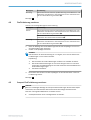
GEFAHR
G
efahr der Unwirksamkeit der Schutzeinrichtung
Der Gefahr bringende Zustand der Maschine wird bei Nichtbeachtung möglicherweise
nicht oder nicht rechtzeitig beendet.
b
Beachten Sie den beiliegenden Sicherheitshinweis.
Der Sicherheits-Lichtvorhang ist unter anderem für nachfolgende Verwendungen nicht
g
eeignet:
•
Im Freien
•
Unter Wasser
•
In explosionsgefährdeten Bereichen
•
In Höhen über 3000 m ü. NHN
•
In Umgebungen mit erhöhter ionisierender Strahlung
Im isolierten 24-V-DC-Versorgungsstromkreis zum Gerät muss eine Sicherung mit
einem Nennstrom von maximal 2 A angebracht werden, um den verfügbaren Strom
zu begrenzen.
Weitere Informationen zur Arbeit mit der Schutzeinrichtung enthält die Maschinendoku‐
mentation oder die Betriebsanleitung der Schutzeinrichtung. Sie finden die EU-Konfor‐
mitätserklärung und die aktuelle Betriebsanleitung der Schutzeinrichtung, indem Sie
auf www.sick.com im Suchfeld die Artikelnummer eingeben (Artikelnummer: siehe
Typenschildeintrag im Feld „Ident. no.“).
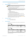
2 Sender und Empfänger
s
Das Symbol kennzeichnet den Sender.
r
Das Symbol kennzeichnet den Empfänger.
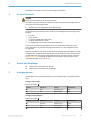
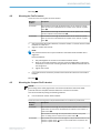
3 Anzeigeelemente
Vollständige Übersicht der LED-Zustände und ihrer Bedeutungen: siehe Betriebsanlei‐
t
ung.
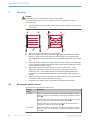
Anzeigen des Senders
Position der LEDs:
A
Position LED-Farbe Anzeige Beschriftung
!
Gelb Betriebsanzeige PWR
"
Rot Fehleranzeige ERR
Anzeigen des Empfängers
P
osition der LEDs:
B
Position LED-Farbe Anzeige Beschriftung
!
Rot/Grün OSSD-Zustand OSSD
"
Rot Fehleranzeige ERR
§
Blau Ausrichtgüte 1, 2, 3, 4
MONTAGEANLEITUNG
8025628/19Z2/2021-03-09 | SICK M O N T A G E A N L E I T U N G | C4-RD
3
Irrtümer und Änderungen vorbehalten

Die blauen Ausrichtgüte-LEDs zeigen in Kombination mit der rot blinkenden ERR-LED
auc
h Fehler an.
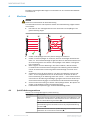
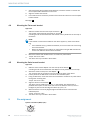
4 Montieren
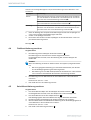
GEFAHR
G
efahr der Unwirksamkeit der Schutzeinrichtung
Zu schützende Personen und Körperteile werden bei Nichtbeachtung möglicherweise
nicht erkannt.
b
Das Ende mit dem Leitungsanschluss muss bei Sender und Empfänger in die
gleiche Richtung zeigen.
180˚
r
s
r
s
b
S
ender und Empfänger auf einem planen Untergrund montieren.
b
Sender und den Empfänger so montieren, dass ein rechteckiges Schutzfeld ent‐
steht, d. h. bei vertikaler Montage auf gleicher Höhe. Für kleinere Korrekturen bei
der Ausrichtung lassen sich Sender und Empfänger in den Haltern in Längsrich‐
tung verschieben.
b
Wenn möglich, die obere Halterung in der Höhe so wählen, dass der Absatz
im Gehäuse des Sicherheits-Lichtvorhangs auf der Halterung aufsitzt. Dadurch
rutscht der Sicherheits-Lichtvorhang während der Montage nicht nach unten
durch.
b
Anzugsdrehmoment für die Schrauben, mit denen die Halterung montiert wird:
5 Nm ... 6 Nm. Anzugsdrehmoment für die Schrauben, mit denen der Sicher‐
heits-Lichtvorhang in der Halterung fixiert wird: 2,5 Nm ... 3 Nm. Höhere Drehmo‐
mente können die Halterung beschädigen, geringere Drehmomente bieten keine
ausreichende Sicherheit gegen ein Verschieben des Sicherheits-Lichtvorhangs.
b
Auf die korrekte Ausrichtung von Sender und Empfänger achten. Die Optiken von
Sender und Empfänger müssen sich gegenüber liegen.
b
Parallelität der Komponenten ggf. mit einer Wasserwaage prüfen.
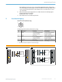
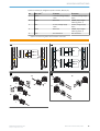
4.1 QuickFix-Halterung montieren
Seitliche und rückseitige Montage der QuickFix-Halterung
Montageart Beschreibung
Seitlich Mit der M5-Schraube durch die QuickFix-Halterung an den Maschinen- oder
Pr
ofilrahmen. Am Maschinen- oder Profilrahmen ist eine Schraubenmutter
oder eine Gewindebohrung erforderlich (!).
Mit der M5-Schraube durch den Maschinen- oder Profilrahmen an die
Q
uickFix-Halterung. Eine Schraubenmutter ist für jede QuickFix-Halterung
erforderlich (").
Mit der M5-Schraube durch die QuickFix-Halterung an den Profilrahmen. Am
Pr
ofilrahmen ist ein Nutenstein erforderlich (§).
MONTAGEANLEITUNG
4
M O N T A G E A N L E I T U N G | C4-RD 8025628/19Z2/2021-03-09 | SICK
Irrtümer und Änderungen vorbehalten

Montageart Beschreibung
Rückseitig Mit der M5-Schraube durch die QuickFix-Halterung an den Maschinen- oder
Pr
ofilrahmen. Am Maschinen- oder Profilrahmen ist eine Schraubenmutter
oder eine Gewindebohrung erforderlich ($).
Montage: C
4.2 FlexFix-Halterung montieren
Seitliche und rückseitige Montage der FlexFix-Halterung
Montageart Beschreibung
Seitlich Mit der M5-Schraube durch die FlexFix-Halterung an den Maschinen- oder
Pr
ofilrahmen. Am Maschinen- oder Profilrahmen ist eine Schraubenmutter
oder eine Gewindebohrung erforderlich (!).
Mit der M5-Schraube durch die FlexFix-Halterung an den Profilrahmen. Am
Pr
ofilrahmen sind 2 Nutensteine erforderlich (").
Rückseitig Mit der M5-Schraube durch die FlexFix-Halterung an den Maschinen- oder
Pr
ofilrahmen. Am Maschinen- oder Profilrahmen ist eine Schraubenmutter
oder eine Gewindebohrung erforderlich (§).
1. Nach der Montage der FlexFix-Halterungen Sender bzw. Empfänger von vorne in
die F
lexFix-Halterungen eindrehen.
2. Sender und Empfänger ausrichten.
HINWEIS
D
as Eindrehen der Schutzeinrichtung ist nur möglich, wenn sich die beiden Flex‐
Fix-Halterungen in einer Flucht befinden.
Empfehlung:
1. Die Schrauben der FlexFix-Halterungen zunächst nur handfest eindrehen.
2. Die beiden FlexFix-Halterungen in eine Flucht bringen. Dazu z. B. ein Richt‐
scheit oder eine Wasserwaage an die nicht benutzten Anschraubflächen der
FlexFix-Halterungen legen.
3. Schrauben festdrehen.
3. Die Position des Senders und des Empfängers mit der M5-Schraube in der Flex‐
F
ix-Halterung fixieren.
Montage:
D
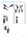
4.3 Compact FlexFix-Halterung montieren
WICHTIG
W
enn bei rückseitiger Montage der Compact FlexFix-Halterungen die Schraubenköpfe
überstehen, kann das Gehäuse des Sicherheits-Lichtvorhangs verkratzt werden.
Das kann mit folgender Maßnahme vermieden werden:
b
Senkkopfschrauben ohne Unterlegscheiben verwenden.
MONTAGEANLEITUNG
8025628/19Z2/2021-03-09 | SICK M O N T A G E A N L E I T U N G | C4-RD
5
Irrtümer und Änderungen vorbehalten

Seitliche und rückseitige Montage der Compact FlexFix-Halterung an einem Maschinen- oder
Pr
ofilrahmen
Montageart Beschreibung
Seitlich Mit der M5-Schraube durch die Compact FlexFix-Halterung an den Maschi‐
nen- oder Pr
ofilrahmen. Am Maschinen- oder Profilrahmen ist eine Schrau‐
benmutter oder eine Gewindebohrung erforderlich (!).
Mit der M5-Schraube durch die Compact FlexFix-Halterung an den Profilrah‐
men. Am Pr
ofilrahmen sind 2 Nutensteine erforderlich (").
Rückseitig Mit der M5-Senkkopfschraube durch die Compact FlexFix-Halterung an den
Ma
schinen- oder Profilrahmen. Am Maschinen- oder Profilrahmen ist eine
Schraubenmutter oder eine Gewindebohrung erforderlich (§).
1. Nach der Montage der Compact FlexFix-Halterungen Sender bzw. Empfänger von
v
orne in die Compact FlexFix-Halterungen eindrehen.
2. Sender und Empfänger ausrichten.
3. Die Position des Senders und des Empfängers mit der M5-Schraube in der Com‐
pact FlexFix-Halterung fixieren.
Montage:
E
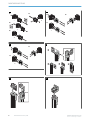
4.4 Flat-Mount-Halterung montieren
Vorgehensweise
1.
Die Halterung auf die Endkappe des Geräts schieben. (
F )
Die Halterung kann horizontal oder vertikal ausgerichtet werden.
Ein Klickgeräusch ist hörbar, wenn die Halterung fest auf der Endkappe des
G
eräts sitzt.
HINWEIS
Wenn die Halterung verdeckt am Gerät montiert wird (Option b) Folgendes beach‐
ten:
•
Mit einem geeigneten Werkzeug (z. B. Schlitzschraubendreher) den Einsatz
aus der Befestigungsbohrung der Halterung drehen.
•
Die Halterung mit einer M6-Senkkopfschraube am Maschinen- oder Profilrah‐
men montieren. Anschließend das Gerät auf die Halterung schieben.
2. Die Halterung mit einer M5-Schraube an einen Maschinen- oder Profilrahmen
mont
ieren.
Drehmoment: 2,5 Nm … 3 Nm
✓
D
as Gerät ist fest in der Halterung montiert.
4.5 Swivel-Mount-Halterung montieren
Vorgehensweise
1.
Den Swivel-Mount-Adapter auf die Endkappe des Geräts schieben. (
G )
Ein Klickgeräusch ist hörbar, wenn der Adapter fest auf der Endkappe sitzt.
2. Den Swivel-Mount-Port auf den Adapter stecken. ( H )
Das Befestigungsloch des Swivel-Mount-Port zeigt zur Rückseite des Geräts.
3. Die M5-Schraube zur Befestigung der beiden Einzelteile lose eindrehen.
4.
Mit einer M5-Schraube die Swivel-Mount-Halterung durch das Befestigungsloch an
einen Maschinen- oder Profilrahmen montieren.
Drehmoment: 4,5 Nm … 5 Nm
5. Das Gerät in der Halterung ausrichten. (
I )
MONTAGEANLEITUNG
6
M O N T A G E A N L E I T U N G | C4-RD 8025628/19Z2/2021-03-09 | SICK
Irrtümer und Änderungen vorbehalten

Das Gerät kann um bis zu ± 270° in der Halterung gedreht werden. Optional ist
eine F
einjustage über das Langloch auf der Frontseite der Halterung möglich. Dazu
einen Innensechskantschlüssel in das Langloch führen und das Gerät um bis zu
± 9° ausrichten.
6. Wenn das Gerät korrekt ausgerichtet ist, die M5-Schraube zur Befestigung der
beiden Einzelteile fest anziehen.
Drehmoment: 3 Nm … 3,5 Nm
✓
D
as Gerät ist fest in der Halterung montiert.
5 Anschlussbelegung
Systemanschluss (M12, 5-polig)
2 1
4
3
5
Pinbelegung Systemanschluss (Stecker M12, 5-polig)
Pin Aderfarbe
1)
s Sender r Empfänger
1 Braun +24 V DC (Eingang Span‐
nungsversorgung)
+24 V DC (Eingang Span‐
nungsversorgung)
2 Weiß Reserviert OSSD1 (Schaltausgang 1)
3 Blau 0 V DC (Eingang Span‐
nun
gsversorgung)
0 V DC (Eingang Span‐
nungsversorgung)
4 Schwarz Reserviert OSSD2 (Schaltausgang 2)
5 Grau Nicht belegt Nicht belegt
1)
Gilt für die als Zubehör empfohlenen Anschlussleitungen.
A
!
PWR
"
ERR
B
!
O
SSD
"
ERR
§
1
2 3
4
MONTAGEANLEITUNG
8025628/19Z2/2021-03-09 | SICK M O N T A G E A N L E I T U N G | C4-RD
7
Irrtümer und Änderungen vorbehalten

C
!
§
$
"
a
b
a
b
D
!
"
§
E
!
"
§
F
CLICK
a
b
c
d
G
CLICK
H
MONTAGEANLEITUNG
8
M O N T A G E A N L E I T U N G | C4-RD 8025628/19Z2/2021-03-09 | SICK
Irrtümer und Änderungen vorbehalten

I
+/-270°
+/-9°
MONTAGEANLEITUNG
8025628/19Z2/2021-03-09 | SICK M O N T A G E A N L E I T U N G | C4-RD
9
Irrtümer und Änderungen vorbehalten


All rights reserved. Subject to change without notice.
1 Safety information
DANGER
H
azard due to lack of effectiveness of the protective device
In the case of non-compliance, it is possible that the dangerous state of the machine
may not be stopped or not stopped in a timely manner.
b
Please observe the safety notes provided.
The safety light curtain is not suitable for the following applications, among others:
•
Out
doors
•
Underwater
•
In explosion-hazardous areas
•
At altitudes over 3,000 m above sea level
•
In environments with enhanced ionizing radiation
A fuse rated maximum 2 A shall be installed in the isolated 24 V DC power supply
circuit to the device in order to limit the available current.
For more information about how to work with the protective device, refer to the machi‐
nery documentation or the operating instructions for the protective device. You can
call up the EU declaration of conformity and the current operating instructions for the
protective device by entering the part number in the search field at www.sick.com (part
number: see the type label entry in the “Ident. no.” field).
2 Sender and receiver
s
The symbol indicates the sender.
r
The symbol indicates the receiver.
3 Status indicators
Complete overview of the LED statuses and their meanings: see operating instructions.
Sender indicators
P
osition of LEDs:
A
Position LED color Display Labeling
!
Yellow Status indicator PWR
"
Red Fault indicator ERR
Receiver indicators
P
osition of LEDs:
B
Position LED color Display Labeling
!
Red/green OSSD status OSSD
"
Red Fault indicator ERR
§
Blue Alignment quality 1, 2, 3, 4
The blue alignment quality light emitting diodes in combination with the red flashing
ER
R LED also denote faults.
MOUNTING INSTRUCTIONS
8025628/19Z2/2021-03-09 | SICK M O U N T I N G I N S T R U C T I O N S | C4-RD
11
Subject to change without notice

4 Mounting
DANGER
H
azard due to lack of effectiveness of the protective device
Persons and parts of the body to be protected may not be recognized in case of
non-observance.
b
The end with the cable connection must point in the same direction for the sender
and receiver.
180˚
r
s
r
s
b
Mount t
he sender and receiver on a level surface.
b
Mount the sender and receiver such that a right-angled protective field is estab‐
lished, i.e., when mounted vertically at the same height. For minor adjustments
when aligning, the sender and receiver can be adjusted longitudinally in the brack‐
ets.
b
If possible, choose a height for the top bracket so that the offset in the safety light
curtain housing is resting on the bracket. This ensures that the safety light curtain
will not slip down during mounting.
b
Tightening torque for the screws used to mount the bracket: 5 Nm … 6 Nm.
Tightening torque for the screws used to secure the safety light curtain in the
bracket: 2.5 Nm … 3 Nm. Higher torques can damage the bracket while lower
torques do not provide adequate fixation to prevent the safety light curtain from
moving.
b
Make sure that the sender and receiver are aligned correctly. The optics of sender
and receiver must be located opposite one another.
b
If necessary, use a spirit level to check that the components are parallel.
4.1 Mounting the QuickFix bracket
Side and rear mounting with the QuickFix bracket
Mounting
me
thod
Description
On the side Fasten the M5 screw to the machine or profile frame through the QuickFix
bracket. A screw nut or threaded hole is required on the machine or profile
frame (!).
Fasten the M5 screw to the QuickFix bracket through the machine or profile
fr
ame. A screw nut is required for each QuickFix bracket (").
Fasten the M5 screw to the profile frame through the QuickFix bracket. A
slidin
g nut is required on the profile frame (§).
On the back Fasten the M5 screw to the machine or profile frame through the QuickFix
br
acket. A screw nut or threaded hole is required on the machine or profile
frame ($).
MOUNTING INSTRUCTIONS
12
M O U N T I N G I N S T R U C T I O N S | C4-RD 8025628/19Z2/2021-03-09 | SICK
Subject to change without notice

Mounting: C
4.2 Mounting the FlexFix bracket
Lateral and rear mounting with the FlexFix bracket
Mounting
method
Description
On the side With the M5 screw through the FlexFix bracket on the machine or profile
frame. A screw nut or threaded hole is required on the machine or profile
frame (!).
With the M5 screw through the FlexFix bracket on the profile frame. 2 sliding
nut
s are required on the profile frame (").
On the back With the M5 screw through the FlexFix bracket on the machine or profile
fr
ame. A screw nut or threaded hole is required on the machine or profile
frame (§).
1. After assembling the FlexFix brackets, screw the sender or receiver into the FlexFix
br
ackets from the front.
2. Align the sender and receiver.
NOTE
T
he protective device can only be screwed in when both FlexFix brackets are in
alignment.
Recommendation:
1. Only hand-tighten the screws on the FlexFix brackets at first.
2. Align the two FlexFix brackets. To do this, place a straightedge or spirit level,
for example, on the screw mounting surfaces of the FlexFix brackets that are
not being used.
3. Tighten the screws.
3. Use an M5 screw to secure the position of the sender and receiver in the FlexFix
br
acket.
Mounting:
D
4.3 Mounting the Compact FlexFix bracket
NOTICE
T
he housing of the safety light curtain can become scratched if the screw heads
protrude when the Compact FlexFix brackets are mounted on the back.
This can be avoided by taking the following measure:
b
Use countersunk screws without washer.
Lateral and rear mounting of the Compact FlexFix bracket on a machine or profile frame
Mounting
me
thod
Description
On the side With the M5 screw through the Compact FlexFix bracket on the machine or
pr
ofile frame. A screw nut or threaded hole is required on the machine or
profile frame (!).
With the M5 screw through the Compact FlexFix bracket on the profile
fr
ame. 2 sliding nuts are required on the profile frame (").
On the back With the M5 countersunk screw through the Compact FlexFix bracket on the
mac
hine or profile frame. A screw nut or threaded hole is required on the
machine or profile frame (§).
MOUNTING INSTRUCTIONS
8025628/19Z2/2021-03-09 | SICK M O U N T I N G I N S T R U C T I O N S | C4-RD
13
Subject to change without notice

1. After assembling the Compact FlexFix brackets, screw the sender or receiver into
t
he Compact FlexFix brackets from the front.
2. Align the sender and receiver.
3. Use an M5 screw to secure the position of the sender and receiver in the Compact
FlexFix bracket.
Montage:
E
4.4 Mounting the Flat mount bracket
Approach
1.
Slide the bracket onto the end cap of the device. (
F )
The bracket can be aligned horizontally or vertically.
A clicking sound can be heard when the bracket is firmly seated on the end cap of
t
he device.
NOTE
If t
he bracket is mounted concealed on the device (option b), observe the follow‐
ing:
•
Use a suitable tool (e.g. slotted screwdriver) to turn the insert out of the fixing
hole of the bracket.
•
Mount the bracket to the machine or profile frame using an M6 countersunk
screw. Then slide the device onto the bracket.
2. Mount the bracket with an M5 screw to a machine or profile frame.
Torque: 2.5 Nm to 3 Nm
✓
T
he device is firmly mounted in the bracket.
4.5 Mounting the Swivel mount bracket
Approach
1.
Slide the swivel mount adapter onto the end cap of the device. (
G )
A clicking sound can be heard when the adapter is firmly seated on the end cap.
2. Attach the swivel mount port to the adapter. ( H )
The mounting hole of the swivel mount port faces the back of the device.
3. Loosely screw in the M5 screw to mount the two individual parts.
4.
Using an M5 screw, mount the swivel mount bracket to a machine or profile frame
through the mounting hole.
Torque: 4.5 Nm to 5 Nm
5. Align the device in the bracket. (
I )
The device can be rotated up to ± 270° in the bracket. Fine adjustment is
pos
sible as an option via the slot on the front of the bracket. To do so, insert a
hexagon key into the slot and align the device by up to ± 9°.
6. When the device is correctly aligned, tighten the M5 screw to mount the two
individual parts.
Torque: 3 Nm to 3.5 Nm
✓
T
he device is firmly mounted in the bracket.
5 Pin assignment
System connection (M12, 5-pin)
2 1
4
3
5
MOUNTING INSTRUCTIONS
14
M O U N T I N G I N S T R U C T I O N S | C4-RD 8025628/19Z2/2021-03-09 | SICK
Subject to change without notice

System connection pin assignment (male connector, M12, 5-pin)
Pin Wire color
1)
s S
ender r Receiver
1 Brown +24 V DC (voltage supply
in
put)
+24 V DC (voltage supply
input)
2 White Reserved OSSD1 (output signal
switching device 1)
3 Blue 0 V DC (voltage supply
input)
0 V DC (voltage supply
input)
4 Black Reserved OSSD2 (output signal
switching device 2)
5 Gray Not connected Not connected
1)
Applies to the connecting cables recommended as accessories.
A
!
PWR
"
ERR
B
!
O
SSD
"
ERR
§
1
2 3
4
C
!
§
$
"
a
b
a
b
D
!
"
§
MOUNTING INSTRUCTIONS
8025628/19Z2/2021-03-09 | SICK M O U N T I N G I N S T R U C T I O N S | C4-RD
15
Subject to change without notice

E
!
"
§
F
CLICK
a
b
c
d
G
CLICK
H
I
+/-270°
+/-9°
MOUNTING INSTRUCTIONS
16
M O U N T I N G I N S T R U C T I O N S | C4-RD 8025628/19Z2/2021-03-09 | SICK
Subject to change without notice

MOUNTING INSTRUCTIONS
8025628/19Z2/2021-03-09 | SICK M O U N T I N G I N S T R U C T I O N S | C4-RD
17
Subject to change without notice

Detailed addresses and further locations at www.sick.com
Australia
Phone +61 (3) 9457 0600
1800 33 48 02 – tollfree
E-Mail [email protected]
Austria
Phone +43 (0) 2236 62288-0
E-Mail of[email protected]
Belgium/Luxembourg
Phone +32 (0) 2 466 55 66
E-Mail [email protected]
Brazil
Phone +55 11 3215-4900
E-Mail [email protected]
Canada
Phone +1 905.771.1444
E-Mail [email protected]
Czech Republic
Phone +420 234 719 500
E-Mail [email protected]
Chile
Phone +56 (2) 2274 7430
E-Mail [email protected]
China
Phone +86 20 2882 3600
E-Mail info.c[email protected]
Denmark
Phone +45 45 82 64 00
E-Mail [email protected]
Finland
Phone +358-9-25 15 800
E-Mail [email protected]
France
Phone +33 1 64 62 35 00
E-Mail [email protected]
Germany
Phone +49 (0) 2 11 53 010
E-Mail [email protected]
Greece
Phone +30 210 6825100
E-Mail [email protected]
Hong Kong
Phone +852 2153 6300
E-Mail [email protected]
Hungary
Phone +36 1 371 2680
E-Mail erte[email protected]
India
Phone +91-22-6119 8900
E-Mail info@sick-india.com
Israel
Phone +972 97110 11
E-Mail [email protected]
Italy
Phone +39 02 27 43 41
E-Mail [email protected]
Japan
Phone +81 3 5309 2112
E-Mail suppor[email protected]
Malaysia
Phone +603-8080 7425
E-Mail enquiry.my@sick.com
Mexico
Phone +52 (472) 748 9451
E-Mail [email protected]
Netherlands
Phone +31 (0) 30 229 25 44
E-Mail [email protected]
New Zealand
Phone +64 9 415 0459
0800 222 278 – tollfree
E-Mail [email protected]
Norway
Phone +47 67 81 50 00
E-Mail [email protected]
Poland
Phone +48 22 539 41 00
E-Mail [email protected]
Romania
Phone +40 356-17 11 20
E-Mail [email protected]
Russia
Phone +7 495 283 09 90
E-Mail [email protected]
Singapore
Phone +65 6744 3732
E-Mail sales.gsg@sick.com
Slovakia
Phone +421 482 901 201
E-Mail [email protected]
Slovenia
Phone +386 591 78849
E-Mail of[email protected]
South Africa
Phone +27 10 060 0550
E-Mail info@sickautomation.co.za
South Korea
Phone +82 2 786 6321/4
E-Mail infokore[email protected]
Spain
Phone +34 93 480 31 00
E-Mail [email protected]
Sweden
Phone +46 10 110 10 00
E-Mail [email protected]
Switzerland
Phone +41 41 619 29 39
E-Mail [email protected]
Taiwan
Phone +886-2-2375-6288
E-Mail [email protected]
Thailand
Phone +66 2 645 0009
E-Mail [email protected]
Turkey
Phone +90 (216) 528 50 00
E-Mail [email protected]
United Arab Emirates
Phone +971 (0) 4 88 65 878
E-Mail [email protected]
United Kingdom
Phone +44 (0)17278 31121
E-Mail [email protected]
USA
Phone +1 800.325.7425
E-Mail [email protected]
Vietnam
Phone +65 6744 3732
E-Mail sales[email protected]
SICK AG | Waldkirch | Germany | www.sick.com
8025628/19Z2/2021-03-09/de, en
-
 1
1
-
 2
2
-
 3
3
-
 4
4
-
 5
5
-
 6
6
-
 7
7
-
 8
8
-
 9
9
-
 10
10
-
 11
11
-
 12
12
-
 13
13
-
 14
14
-
 15
15
-
 16
16
-
 17
17
-
 18
18


in anderen Sprachen
- English: SICK C4-RD
Verwandte Artikel
-
SICK Sense2 Mounting instructions
-
-
-
-
-
-
-
-
-