
ENGLISH ITALIANO FRANÇAIS DEUTSCH
РУССКИЙ
EN
English - Instructions manual
IT
Italiano - Manuale di istruzioni
FR
Français - Manuel d’instructions
DE
Deutsch - Bedienungslanleitung
RU
Русский - Руководство по эксплуатации
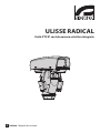
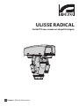
ULISSE RADICAL
PTZ unit with integrated camera and lens


EN
English - Instruction manual
ENGLISH
ULISSE RADICAL
PTZ unit with integrated Kamera and lens


Instruction manual - English - EN
3MNVCUPKHXL_1625_EN
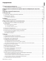
Contents
ENGLISH 1
1 About this manual ......................................................................................................... 6
1.1 Typographical conventions .................................................................................................................................. 6
2 Notes on copyright and information on trademarks .................................................. 6
3 Safety rules..................................................................................................................... 6
4 Identication .................................................................................................................. 9
4.1 Product description and type designation..................................................................................................... 9
4.2 Product marking ...................................................................................................................................................... 9
4.2.1 Checking the markings ......................................................................................................................................................... 9
5 Versions ........................................................................................................................10
5.1 LED illuminators .....................................................................................................................................................10
6 Preparing the product for use .................................................................................... 10
6.1 Safety precautions before use ...........................................................................................................................10
6.2 Unpacking ................................................................................................................................................................ 11
6.2.1 Removal of the protective packaging ............................................................................................................................ 11
6.2.1.1 How to open the housing ........................................................................................................................................................................ 11
6.2.1.2 Remove the protective packaging .......................................................................................................................................................11
6.3 Contents .................................................................................................................................................................... 12
6.4 Safely disposing of packaging material .........................................................................................................12
6.5 Preparatory work before installation .............................................................................................................. 12
6.5.1 Attaching the bracket ..........................................................................................................................................................12
6.5.2 Cables management ............................................................................................................................................................12
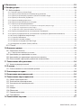
7 Installation ................................................................................................................... 13
7.1 Connecting the cables to the base ..................................................................................................................13
7.2 Fixing the base to the support ..........................................................................................................................14
7.3 Connector board description ............................................................................................................................ 14
7.4 Connection of the power supply line ............................................................................................................. 15
7.4.1 24Vac power line connection ............................................................................................................................................ 16
7.4.2 120Vac and 230Vac power line connection .................................................................................................................16
7.4.3 Connection of the alarm inputs, of the twilight switch and of the relays .........................................................17
7.5 Connection of the Ethernet cable....................................................................................................................17
7.6 Fixing the upper body ..........................................................................................................................................18
7.7 Counterweights installation ..............................................................................................................................18
7.8 LED illuminators installation .............................................................................................................................. 19
7.8.1 Counterweight removal ......................................................................................................................................................19
7.8.2 Fitting the illuminator on the bracket ............................................................................................................................ 19
7.9 Connection of the LED illuminators ................................................................................................................ 20
7.10 LED illuminator activation and adjustment instructions ...................................................................... 20
7.10.1 Description of the LED illuminator ...............................................................................................................................20
7.10.2 LED illuminator switching on threshold adjustment .............................................................................................21
7.10.3 LED illuminator power adjustment ..............................................................................................................................21
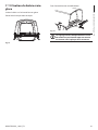
7.11 Fastening of the wiper blade ..........................................................................................................................22
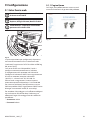
8 Switching on ................................................................................................................23

EN - English - Instruction manual
4 MNVCUPKHXL_1625_EN
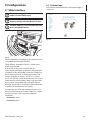
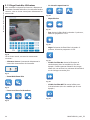
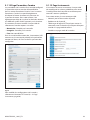
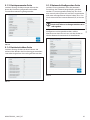
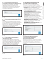
9 Conguration ...............................................................................................................24
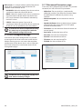
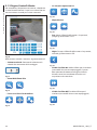
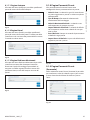
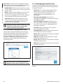
9.1 Web interface ..........................................................................................................................................................24
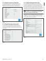
9.1.1 Home Page ............................................................................................................................................................................... 24
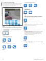
9.1.2 User Controls page ................................................................................................................................................................25
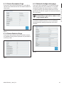
9.1.3 Device Parameters Page ......................................................................................................................................................26
9.1.4 Device Statistics Page ..........................................................................................................................................................26
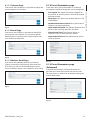
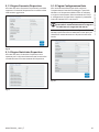
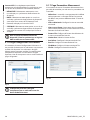
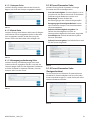
9.1.5 Network Conguration page ............................................................................................................................................26
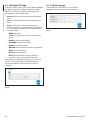
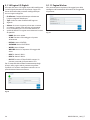
9.1.6 User Conguration page ..................................................................................................................................................... 27
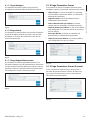
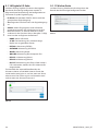
9.1.7 Movement Parameters page .............................................................................................................................................27
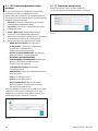
9.1.7.1 Autopan Page...............................................................................................................................................................................................28
9.1.7.2 Patrol Page ....................................................................................................................................................................................................28
9.1.7.3 Motions Recall Page ................................................................................................................................................................................... 28
9.1.8 Preset Parameters page .......................................................................................................................................................28
9.1.9 Preset Parameters page (Advanced) ...............................................................................................................................28
9.1.10 Digital I/O Page ....................................................................................................................................................................29
9.1.11 Washer page .........................................................................................................................................................................29
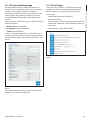
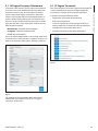
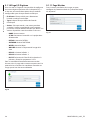
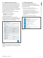
9.1.12 Camera Settings page .......................................................................................................................................................30
9.1.13 Tools Page ..............................................................................................................................................................................30
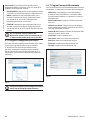
9.1.14 Factory Default .....................................................................................................................................................................31
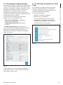
9.2 VTTunnel ................................................................................................................................................................... 31
10 Accessories ................................................................................................................. 32
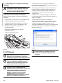
10.1 Washer ..................................................................................................................................................................... 32
10.1.1 Washing system connection ...........................................................................................................................................32
10.2 Wall mount bracket ............................................................................................................................................33
10.3 Parapet bracket .................................................................................................................................................... 33
10.4 Power supply with illuminator control ........................................................................................................33
11 Maintenance ..............................................................................................................34
11.1 Fuses replacement .............................................................................................................................................. 34
12 Cleaning ..................................................................................................................... 34
12.1 Window and plastic cover cleaning .............................................................................................................. 34
13 Disposal of waste materials ......................................................................................34
14 Troubleshooting ........................................................................................................ 34
15 Technical data ............................................................................................................ 35
15.1 General .................................................................................................................................................................... 35
15.2 Mechanical .............................................................................................................................................................35
15.3 Electrical .................................................................................................................................................................35
15.4 Communications .................................................................................................................................................35
15.5 Camera ....................................................................................................................................................................36
15.6 Lenses ...................................................................................................................................................................... 36
15.7 Environment..........................................................................................................................................................36
15.8 Certications ......................................................................................................................................................... 36
16 Technical drawings .................................................................................................... 37

Instruction manual - English - EN
5MNVCUPKHXL_1625_EN
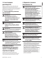
1 About this manual
Read all the documentation supplied carefully before
installing and using this unit. Keep the manual in a
convenient place for future reference.
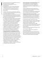
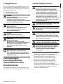
1.1 Typographical conventions
DANGER!
High level hazard.
Risk of electric shock. Disconnect the
power supply before proceeding with any
operation, unless indicated otherwise.
DANGER!
Hot surface.
Avoid contact. Surfaces are hot and may
cause personal injury if touched.
DANGER!
Mechanical hazard.
Risk of crushing or shearing.
CAUTION!
Medium level hazard.
This operation is very important for the
system to function properly. Please read
the procedure described very carefully and
carry it out as instructed.
INFO
Description of system specications.
We recommend reading this part carefully
in order to understand the subsequent
stages.
2 Notes on copyright and
information on trademarks
The quoted names of products or companies are
trademarks or registered trademarks.
3 Safety rules
CAUTION! The electrical system to which
the unit is connected must be equipped
with a 20A max automatic bipolar circuit
breaker. This circuit breaker must be of
the Listed type. The minimum distance
between the circuit breaker contacts must
be 3mm (0.1in). The circuit breaker must be
provided with protection against the fault
current towards the ground (dierential)
and the overcurrent (magnetothermal).
CAUTION! Hazardous moving parts. Keep
ngers and other body parts away.
CAUTION! Device installation and
maintaining must be performed by
specialist technical sta only.
CAUTION! For continued protection against
risk of re, replace only with same type and
rating of fuse. Fuses must be replaced only
by service personnel.
CAUTION! TNV-1 installation type. The
installation is type TNV-1, do not connect it
to SELV circuits.
CAUTION! In order to reduce the risk of re,
only use UL Listed or CSA certied cables
with sections greater than or equal to
0.14mm² (26AWG).
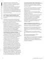
• The manufacturer declines all responsibility
for any damage caused by an improper use
of the appliances mentioned in this manual.
Furthermore, the manufacturer reserves the right
to modify its contents without any prior notice.
The documentation contained in this manual has
been collected with great care. The manufacturer,
however, cannot take any liability for its use. The
same thing can be said for any person or company
involved in the creation and production of this
manual.

EN - English - Instruction manual
6 MNVCUPKHXL_1625_EN
• Before starting any operation, make sure the
power supply is disconnected.
• Be careful not to use cables that seem worn or old.
• Never, under any circumstances, make any
changes or connections that are not shown in
this handbook. Improper use of the appliance
can cause serious hazards, risking the safety of
personnel and of the installation.
• Use only original spare parts. Non-original spare
parts could cause re, electrical discharge or other
hazards.
• Before proceeding with installation, check the
supplied material to make sure it corresponds
to the order specication by examining the
identication labels (4.2 Product marking, page 9).
• Installation category (also called Overvoltage
Category) species the level of mains voltage
surges that the equipment will be subjected to.
The category depends upon the location of the
equipment, and on any external surge protection
provided. Equipment in an industrial environment,
directly connected to major feeders/short branch
circuits, is subjected to Installation Category III. If
this is the case, a reduction to Installation Category
II is required. This can be achieved by use of an
insulating transformer with an earthed screen
between primary and secondary, or by tting UL
listed Surge Protective Devices (SPDs) from live
to neutral and from neutral to earth. Listed SPDs
shall be designed for repeated limiting of transient
voltage surges, suitable rated for operating voltage
and designated as follows: Type 2 (Permanently
connected SPDs intended for installation on the
load side of the service equipment overcurrent
device); Nominal Discharge Current (In) 20kA min.
For example: FERRAZ SHAWMUT, STT2240SPG-
CN, STT2BL240SPG-CN rated 120Vac/240Vac,
(In=20kA). Maximum distance between installation
and reduction is 5m.
• This device was designed to be permanently
secured and connected on a building or on a
suitable structure. The device must be permanently
secured and connected before any operation.
• A power disconnect device must be included
in the electrical installation, and it must be very
quickly recognizable and operated if needed.
• The separate protective earthing terminal provided
on this product shall be permanently connected
to earth.
• Connect the device to a power source
corresponding to the indications given on the
marking label. Before proceeding with installation
make sure that the power line is properly isolated.
The supply voltage should never exceed the limit
(±10%).
• Power supply must be provided with a SELV type,
24Vac, 8A isolated source derived from a double
isolation UL Listed transformer specially protected
in output.
• The appliance includes moving parts. Make sure
that the unit is positioned where it is inaccessible
under normal operating conditions.
• Attach the Dangerous Moving Parts label near the
device. (Fig. 3, page10).
• Do not use the appliance in the presence of
inammable substances.
• To connect the power supply line use the
appropriate junction-box (UPTJBUL). For further
information, refer to the product use and
installation manual.

Instruction manual - English - EN
7MNVCUPKHXL_1625_EN
• Do not allow children or unauthorised people to
use the appliance.
• Only skilled personnel should carry out
maintenance on the device. When carrying out
maintenance, the operator is exposed to the risk of
electrocution and other hazards.
• Use only the accessories indicated by the
manufacturer. Any change that is not expressly
approved by the manufacturer will invalidate the
guarantee.
• Before connecting all the cables make sure the
device is properly connected to the earth circuit.
• If the device has to be removed from the
installation, always disconnect the earth cable last.
• Take all necessary precautions to prevent the
apparatus from being damaged by electrostatic
discharge.
• The unit has been made for connection using a
3-pole cable. To make a correct connection to
the earth circuit, follow the instructions in this
handbook.
• Handle the unit with great care, high mechanical
stress could damage it.
• Make especially sure that the power supply line is
insulated at a sucient distance from all the other
cables, including lightning protection devices.
• If it is necessary to transport the device, this should
be done with great care. Abrupt stops, bumps and
violent impact could damage the unit or injure the
user.

EN - English - Instruction manual
8 MNVCUPKHXL_1625_EN
4 Identication
4.1 Product description and type
designation
ULISSE RADICAL is the rst Videotec ready to use
network Full HD PTZ camera system that integrates
exceptional factory-assembled combinations of
camera and lens, Full HD 1080p, 60fps and 1/2" CMOS
sensor, for day and night time broadcast quality video
of extended outdoor areas.
To meet the most demanding video surveillance
specications, this PTZ camera unit is supplied
with 18x or 33x lenses equipped with an advanced
autofocus that allows and automatically maintains
the focus on subjects at far distances with sharp
details.
ULISSE RADICAL is certied ONVIF Prole S and is
compatible with most VMS on the market.
The Videotec's PTZ ASSISTANT plug-in software
supports any VMS with the control of all special
functions such as wiper, washer pump, IR and Auto
Focus.
Powerful motors guarantee exceptionally smooth
tracking, even at a minimum speed of 0.02°/sec.
The performance remains optimal in complete
darkness thanks to powerful LED illuminators that
can reach distances of over 300m (985ft) with two
UPTIRN illuminators (10°, 850nm).
ULISSE RADICAL with 33x zoom features a Thermal
Compensation System and a Visible Cut Filter.
Due to its characteristics of accuracy, reliability and
robustness, this PTZ camera is the ideal solution for
the visual control of large outdoor areas, such as:
border patrol, harbour surveillance, long distance
perimeter surveillance, trac and highway control,
military installations.
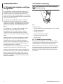
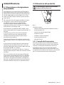
4.2 Product marking
Pan & tilt devices have a label complying
with CE markings.
Fig. 1
The label shows:
• Model identication code (Extended 3/9 bar code).
• Supply voltage (Volt).
• Frequency (Hertz).
• Current consumption (Amps).
• Weatherproof standard (IP).
• Serial number.
4.2.1 Checking the markings
Before proceeding further with installation, make
sure the material supplied corresponds to the order
specication by examining the marking labels.
Never, under any circumstances, make any changes
or connections that are not shown in this handbook.
Improper use of the appliance can cause serious
hazards, risking the safety of personnel and of the
installation.

Instruction manual - English - EN
9MNVCUPKHXL_1625_EN
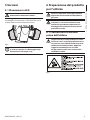
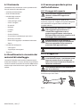
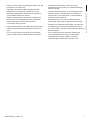
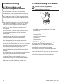
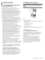
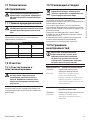
5 Versions
5.1 LED illuminators
The version with LED illuminators can only
powered at 24Vac.
The pan & tilt can be tted with bracket for 2
VIDEOTEC LED illuminators for night surveillance
(illuminators not included).
Fig. 2
For further information refer to the relative
chapter (7.8 LED illuminators installation,
page19).
6 Preparing the product for
use
Any change that is not expressly approved
by the manufacturer will invalidate the
guarantee.
The unit must not be dismantled or
tampered with. The only exceptions
are those concerning the assembly and
maintenance operations stipulated in this
manual.
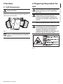
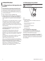
6.1 Safety precautions before use
The appliance includes moving parts. Make
sure that the unit is positioned where it
is inaccessible under normal operating
conditions. Attach the warning label
supplied with the appliance, placing it near
the unit so that it can be seen easily.
Fig. 3

EN - English - Instruction manual
10 MNVCUPKHXL_1625_EN
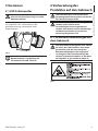
6.2 Unpacking
When the product is delivered, make sure that the
package is intact and that there are no signs that it
has been dropped or scratched.
If there are obvious signs of damage, contact the
supplier immediately.
When returning a faulty product we recommend
using the original packaging for shipping.
Keep the packaging in case you need to send the
product for repairs.
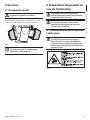
Unpack the sunshield of the device, taking
care not to damage the housing.
6.2.1 Removal of the protective
packaging
Remove the protective packaging before installing
the device.
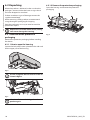
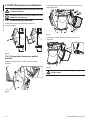
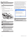
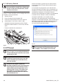
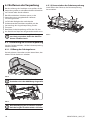
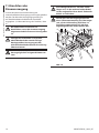
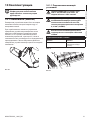
6.2.1.1 How to open the housing
Loosen the leak-proof screws placed on the sides and
lift the upper part of the housing.
Fig. 4
First of all tighten the two central screws as
shown in gure.
Fig. 5
After installation and wiring, close the
product again.
6.2.1.2 Remove the protective packaging
Open the housing and remove the protective
packaging.
Fig. 6

Instruction manual - English - EN
11MNVCUPKHXL_1625_EN
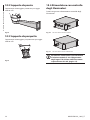
6.3 Contents
Check the contents to make sure they correspond
with the list of materials as below:
• Positioning unit
• Power supply base
• Accessories package:
• Serial adaptor
• Serial extension cable
• Allen wrenches
• Spacers
• Label
• Cable ties
• Ferrite
• Silicone sheath
• Reduction gaskets for cable glands
• Instruction manual
• Attachment plate for desiccant bag
• Bolts and screws
• Counterweights package:
• Counterweights
• Counterweights brackets
• Sunshield
6.4 Safely disposing of packaging
material
The packaging material can all be recycled. The
installer technician will be responsible for separating
the material for disposal, and in any case for
compliance with the legislation in force where the
device is to be used.
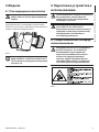
6.5 Preparatory work before
installation
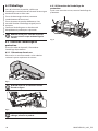
6.5.1 Attaching the bracket
For installations subject to vibrations, only
use the parapet bracket.
Dierent types of supports are available (10
Accessories, page32). Choose a suitable bracket for
the installation and follow all the instructions in the
suggested chapter.
Take special care when attaching and
fastening down the apparatus. The
clamping system must be able to support
at least 4 times the weight of the entire
equipment, including P&T, lenses and
camera.
The device should be assembled vertically.
Any other position could impair the
performance of the appliance.
Do not attach the device upside down.
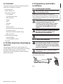
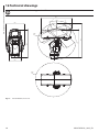
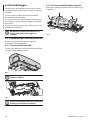
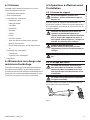
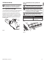
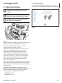
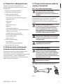
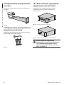
6.5.2 Cables management
The connection cables should not be
accessible from the outside. It is necessary
to fasten the cables securely to the support
in order to prevent excessive weight pulling
them out accidentaly.
You must use cables suited to the type of
installation.
Insert the cables into the support so that they
protrude by about 50cm.
50cm50cm
Fig. 7

EN - English - Instruction manual
12 MNVCUPKHXL_1625_EN
7 Installation
Never, under any circumstances, make
any changes or connections that are not
shown in this handbook. Failure to follow
the connection instructions that are given
in the handbook may create serious safety
hazards for people and for the installation.
Do not change the wiring in the product
as it is supplied to you. Failure to follow
this instruction may create serious safety
hazards for people and for the installation,
and will also invalidate the guarantee.
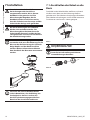
If using the washer kit, the nozzle support
should be installed before positioning
the pan & tilt and the wiring. For further
explanations see the specic handbook for
the kit.
Fig. 8
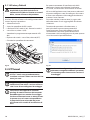
Inside the bottom cover there is a desiccant
bag that is used to prevent moisture
formation in the base and near the
connector boards. Remove the bag before
installation.
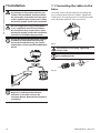
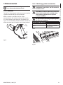
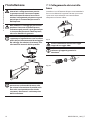
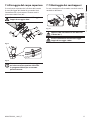
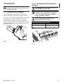
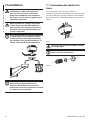
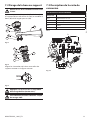
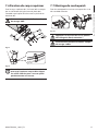
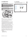
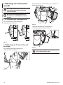
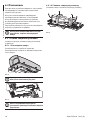
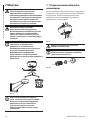
7.1 Connecting the cables to the
base
Insert the cables into the cable glands holding the
base at about 20cm from the support. Tighten the
cable glands. The cable glands are suitable for cables
with a diameter between 5mm and 10 mm.
Fig. 9
Pay attention to the xing. Tightening
torque: 5Nm.
For cables diameter from 3mm to 7mm use
the supplied gaskets.
Fig. 10

Instruction manual - English - EN
13MNVCUPKHXL_1625_EN
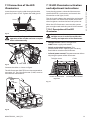
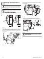
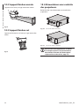
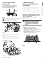
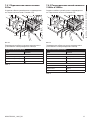
7.2 Fixing the base to the support
Use the screws and the washers supplied
with the base.
Once you have positioned the gasket (01), x the
base (02) onto the bracket (03) with screws (04),
serrated washers (05) and screw rings (06).
01
03
06
05
04
02
Fig. 11
01
03
06
05
04
02
Fig. 12
Align the 3 notches on the base with those on the
support as shown in the following gure.
Fig. 13
Apply a thread-locker on the holes of the
screws (Loctite 243®).
Pay attention to the xing. Tightening
torque: 6Nm.
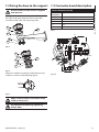
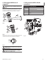
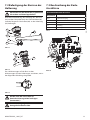
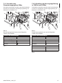
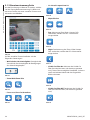
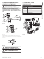
7.3 Connector board description
CONNECTOR BOARD DESCRIPTION
Connector/
Component
Function
CN1 Board power supply
CN4 Signal cables
Ethernet Ethernet
F1 Fuse
F2 Fuse
Tab. 1
F1
CN1
F2
CN4
Ethernet
Fig. 14

EN - English - Instruction manual
14 MNVCUPKHXL_1625_EN
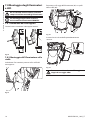
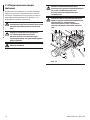
7.4 Connection of the power
supply line
Depending on the version, the device can be
provided with dierent power supply voltages. The
power supply voltage is indicated on the product
identication label. (4.2 Product marking, page9).
Electrical connections must be performed
with the power supply disconnected and
the circuit-breaker open.
When commencing installation make sure
that the specications for the power supply
for the installation correspond with those
required by the device.
Check that the power supply socket and
cable are adequately dimensioned.
Earth cable should be about 10mm longer
than the other two, so that it will not be
disconnected accidentally if pulled.
The power supply cable must be covered
by the silicone sheath (01) supplied. The
silicone sheath must be fastened with the
corresponding cable tie (02).
Fig. 15
CN1
N
L
a
01
02

Instruction manual - English - EN
15MNVCUPKHXL_1625_EN
7.4.1 24Vac power line connection
Cut the cables to the correct length and make the
connections. Connect the power supply to the
terminal: CN1.
CN1
24Vac 24Vac
a
Fig. 16
Connect the power supply cables as described in the
table below.
CONNECTION OF THE POWER SUPPLY LINE
Colour Terminals
Power supply 24Vac
Dened by the installer 24Vac
Dened by the installer 24Vac
Yellow/Green
Tab. 2
7.4.2 120Vac and 230Vac power line
connection
Cut the cables to the correct length and make the
connections. Connect the power supply to the
terminal: CN1.
CN1
N L
GND
a
Fig. 17
Connect the power supply cables as described in the
table below.
CONNECTION OF THE POWER SUPPLY LINE
Colour Terminals
Power supply 230Vac
Blue N (Neutral)
Brown L (Phase)
Yellow/Green
Power supply 120Vac
Blue N (Neutral)
Brown L (Phase)
Yellow/Green
Tab. 3

EN - English - Instruction manual
16 MNVCUPKHXL_1625_EN
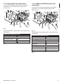
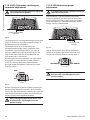
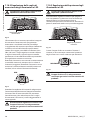
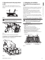
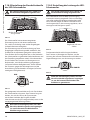
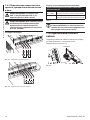
7.4.3 Connection of the alarm inputs, of
the twilight switch and of the relays
CAUTION! TNV-1 installation type. The
installation is type TNV-1, do not connect it
to SELV circuits.
CAUTION! In order to reduce the risk of re,
only use UL Listed or CSA certied cables
with sections greater than or equal to
0.14mm² (26AWG).
Standard version
O1 C1 O2 C2
V V
Fig. 18 Relay contact connection.
AL4
AL3
AL2
AL1
AGND
Fig. 19 Alarms connection.
Version with LED illuminators
CONNECTION OF THE ALARM INPUTS, OF THE TWILIGHT SWITCH
AND OF THE RELAYS
AL1, AL2, AL3,
AL4 e AGND
Self-powered alarm inputs referred to the AGND
shared terminal
O1-C1 e O2-C2 Clean output contacts, can be activated by alarm
or by user control
Tab. 4
Connect the twilight switch to the AGND
and AL1 terminals. AL1 is the default alarm
contact for the light sensitive switch.
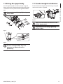
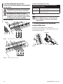
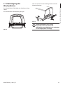
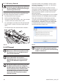
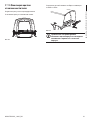
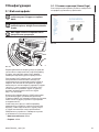
7.5 Connection of the Ethernet
cable
Connect the ethernet cable to the relative connector
(Ethernet, 7.3 Connector board description, page14).
Ethernet
Fig. 20

Instruction manual - English - EN
17MNVCUPKHXL_1625_EN
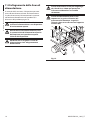
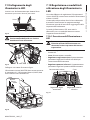
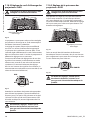
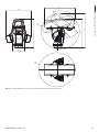
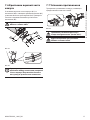
7.6 Fixing the upper body
Fix the upper body (01) to the base (02) using the
xing screws (03) equipped with gaskets (04). Make
sure the base seal is present and in good condition
(05).
Pay attention to the xing. Tightening
torque: 4Nm.
02
03
05
04
01
Fig. 21
Fig. 22
There is one anchoring position between
the base and upper body. Align side
projections to obtain the correct
positioning.
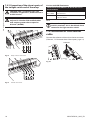
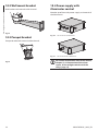
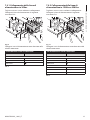
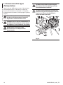
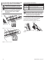
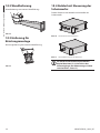
7.7 Counterweights installation
Fasten the counterweights to the housing using the
screws and washers supplied.
Fig. 23
Apply a thread-locker on the holes of the
screws (Loctite 243®).
Pay attention to the xing. Tightening
torque: 16Nm.

EN - English - Instruction manual
18 MNVCUPKHXL_1625_EN
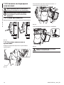
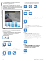
7.8 LED illuminators installation
To work properly both illuminators must be
installed together.
From Pan & Tilt, it is only possible to install
VIDEOTEC illuminators.
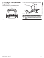
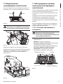
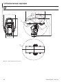
7.8.1 Counterweight removal
Undo the screws and remove the external
counterweights.
Fig. 24
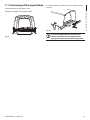
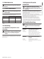
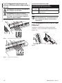
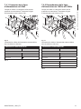
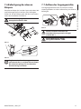
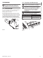
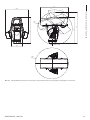
7.8.2 Fitting the illuminator on the
bracket
Identify the front holes on the counter-weight
bracket.
Fig. 25
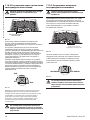
Place the xings of the illuminator (01) on those of
the bracket (02).
01
02
01
02
Fig. 26
Tighten the screws and the washers previously
removed.
Fig. 27
Pay attention to the xing. Tightening
torque: 6Nm.
Seite wird geladen ...
Seite wird geladen ...
Seite wird geladen ...
Seite wird geladen ...
Seite wird geladen ...
Seite wird geladen ...
Seite wird geladen ...
Seite wird geladen ...
Seite wird geladen ...
Seite wird geladen ...
Seite wird geladen ...
Seite wird geladen ...
Seite wird geladen ...
Seite wird geladen ...
Seite wird geladen ...
Seite wird geladen ...
Seite wird geladen ...
Seite wird geladen ...
Seite wird geladen ...
Seite wird geladen ...
Seite wird geladen ...
Seite wird geladen ...
Seite wird geladen ...
Seite wird geladen ...
Seite wird geladen ...
Seite wird geladen ...
Seite wird geladen ...
Seite wird geladen ...
Seite wird geladen ...
Seite wird geladen ...
Seite wird geladen ...
Seite wird geladen ...
Seite wird geladen ...
Seite wird geladen ...
Seite wird geladen ...
Seite wird geladen ...
Seite wird geladen ...
Seite wird geladen ...
Seite wird geladen ...
Seite wird geladen ...
Seite wird geladen ...
Seite wird geladen ...
Seite wird geladen ...
Seite wird geladen ...
Seite wird geladen ...
Seite wird geladen ...
Seite wird geladen ...
Seite wird geladen ...
Seite wird geladen ...
Seite wird geladen ...
Seite wird geladen ...
Seite wird geladen ...
Seite wird geladen ...
Seite wird geladen ...
Seite wird geladen ...
Seite wird geladen ...
Seite wird geladen ...
Seite wird geladen ...
Seite wird geladen ...
Seite wird geladen ...
Seite wird geladen ...
Seite wird geladen ...
Seite wird geladen ...
Seite wird geladen ...
Seite wird geladen ...
Seite wird geladen ...
Seite wird geladen ...
Seite wird geladen ...
Seite wird geladen ...
Seite wird geladen ...
Seite wird geladen ...
Seite wird geladen ...
Seite wird geladen ...
Seite wird geladen ...
Seite wird geladen ...
Seite wird geladen ...
Seite wird geladen ...
Seite wird geladen ...
Seite wird geladen ...
Seite wird geladen ...
Seite wird geladen ...
Seite wird geladen ...
Seite wird geladen ...
Seite wird geladen ...
Seite wird geladen ...
Seite wird geladen ...
Seite wird geladen ...
Seite wird geladen ...
Seite wird geladen ...
Seite wird geladen ...
Seite wird geladen ...
Seite wird geladen ...
Seite wird geladen ...
Seite wird geladen ...
Seite wird geladen ...
Seite wird geladen ...
Seite wird geladen ...
Seite wird geladen ...
Seite wird geladen ...
Seite wird geladen ...
Seite wird geladen ...
Seite wird geladen ...
Seite wird geladen ...
Seite wird geladen ...
Seite wird geladen ...
Seite wird geladen ...
Seite wird geladen ...
Seite wird geladen ...
Seite wird geladen ...
Seite wird geladen ...
Seite wird geladen ...
Seite wird geladen ...
Seite wird geladen ...
Seite wird geladen ...
Seite wird geladen ...
Seite wird geladen ...
Seite wird geladen ...
Seite wird geladen ...
Seite wird geladen ...
Seite wird geladen ...
Seite wird geladen ...
Seite wird geladen ...
Seite wird geladen ...
Seite wird geladen ...
Seite wird geladen ...
Seite wird geladen ...
Seite wird geladen ...
Seite wird geladen ...
Seite wird geladen ...
Seite wird geladen ...
Seite wird geladen ...
Seite wird geladen ...
Seite wird geladen ...
Seite wird geladen ...
Seite wird geladen ...
Seite wird geladen ...
Seite wird geladen ...
Seite wird geladen ...
Seite wird geladen ...
Seite wird geladen ...
Seite wird geladen ...
Seite wird geladen ...
Seite wird geladen ...
Seite wird geladen ...
Seite wird geladen ...
Seite wird geladen ...
Seite wird geladen ...
Seite wird geladen ...
Seite wird geladen ...
Seite wird geladen ...
Seite wird geladen ...
Seite wird geladen ...
Seite wird geladen ...
Seite wird geladen ...
Seite wird geladen ...
Seite wird geladen ...
Seite wird geladen ...
Seite wird geladen ...
Seite wird geladen ...
Seite wird geladen ...
Seite wird geladen ...
Seite wird geladen ...
Seite wird geladen ...
Seite wird geladen ...
Seite wird geladen ...
Seite wird geladen ...
Seite wird geladen ...
Seite wird geladen ...
Seite wird geladen ...
Seite wird geladen ...
Seite wird geladen ...
Seite wird geladen ...
Seite wird geladen ...
Seite wird geladen ...
Seite wird geladen ...
Seite wird geladen ...
-
 1
1
-
 2
2
-
 3
3
-
 4
4
-
 5
5
-
 6
6
-
 7
7
-
 8
8
-
 9
9
-
 10
10
-
 11
11
-
 12
12
-
 13
13
-
 14
14
-
 15
15
-
 16
16
-
 17
17
-
 18
18
-
 19
19
-
 20
20
-
 21
21
-
 22
22
-
 23
23
-
 24
24
-
 25
25
-
 26
26
-
 27
27
-
 28
28
-
 29
29
-
 30
30
-
 31
31
-
 32
32
-
 33
33
-
 34
34
-
 35
35
-
 36
36
-
 37
37
-
 38
38
-
 39
39
-
 40
40
-
 41
41
-
 42
42
-
 43
43
-
 44
44
-
 45
45
-
 46
46
-
 47
47
-
 48
48
-
 49
49
-
 50
50
-
 51
51
-
 52
52
-
 53
53
-
 54
54
-
 55
55
-
 56
56
-
 57
57
-
 58
58
-
 59
59
-
 60
60
-
 61
61
-
 62
62
-
 63
63
-
 64
64
-
 65
65
-
 66
66
-
 67
67
-
 68
68
-
 69
69
-
 70
70
-
 71
71
-
 72
72
-
 73
73
-
 74
74
-
 75
75
-
 76
76
-
 77
77
-
 78
78
-
 79
79
-
 80
80
-
 81
81
-
 82
82
-
 83
83
-
 84
84
-
 85
85
-
 86
86
-
 87
87
-
 88
88
-
 89
89
-
 90
90
-
 91
91
-
 92
92
-
 93
93
-
 94
94
-
 95
95
-
 96
96
-
 97
97
-
 98
98
-
 99
99
-
 100
100
-
 101
101
-
 102
102
-
 103
103
-
 104
104
-
 105
105
-
 106
106
-
 107
107
-
 108
108
-
 109
109
-
 110
110
-
 111
111
-
 112
112
-
 113
113
-
 114
114
-
 115
115
-
 116
116
-
 117
117
-
 118
118
-
 119
119
-
 120
120
-
 121
121
-
 122
122
-
 123
123
-
 124
124
-
 125
125
-
 126
126
-
 127
127
-
 128
128
-
 129
129
-
 130
130
-
 131
131
-
 132
132
-
 133
133
-
 134
134
-
 135
135
-
 136
136
-
 137
137
-
 138
138
-
 139
139
-
 140
140
-
 141
141
-
 142
142
-
 143
143
-
 144
144
-
 145
145
-
 146
146
-
 147
147
-
 148
148
-
 149
149
-
 150
150
-
 151
151
-
 152
152
-
 153
153
-
 154
154
-
 155
155
-
 156
156
-
 157
157
-
 158
158
-
 159
159
-
 160
160
-
 161
161
-
 162
162
-
 163
163
-
 164
164
-
 165
165
-
 166
166
-
 167
167
-
 168
168
-
 169
169
-
 170
170
-
 171
171
-
 172
172
-
 173
173
-
 174
174
-
 175
175
-
 176
176
-
 177
177
-
 178
178
-
 179
179
-
 180
180
-
 181
181
-
 182
182
-
 183
183
-
 184
184
-
 185
185
-
 186
186
-
 187
187
-
 188
188
-
 189
189
-
 190
190
-
 191
191
-
 192
192
-
 193
193
-
 194
194
-
 195
195
-
 196
196


in anderen Sprachen
- français: Videotec ULISSE RADICAL Manuel utilisateur
- italiano: Videotec ULISSE RADICAL Manuale utente
Verwandte Artikel
-
Videotec ULISSE RADICAL Benutzerhandbuch
-
Videotec ULISSE MAXI NETCAM Benutzerhandbuch
-
-
-
Videotec ULISSE2 Benutzerhandbuch
-
-
Videotec MAXIMUS MVXHD Benutzerhandbuch
-
Videotec UPTIRPS Benutzerhandbuch
-
-
Andere Dokumente
-
aerauliqa QCmev Bedienungsanleitung
-
Axis Q8722-E Installationsanleitung
-
Axis Communications Q8722 Benutzerhandbuch
-
Promate Patrol-Pro Benutzerhandbuch
-
Eneo IRLED-40 Series Full Manual
-
Dedicated Micros 2020 Infra Red Illuminator Bedienungsanleitung
-
CAME OH/GW Installationsanleitung
-
TRONIC KH 1596 TWILIGHT SWITCH Bedienungsanleitung
-
Bacharach MGS-150 Schnellstartanleitung