
ENGLISHITALIANOFRANÇAISDEUTSCH
РУССКИЙ
EN
English - Instructions manual
IT
Italiano - Manuale di istruzioni
FR
Français - Manuel d’instructions
DE
Deutsch - Bedienungslanleitung
RU
Русский - Руководство по эксплуатации
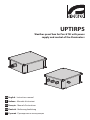
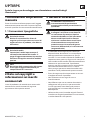
UPTIRPS
Weather-proof box for Pan & Tilt with power
supply and control of the illuminators


Instructions manual - English - EN
1MNVKUPTPSUL_1449_EN
ENGLISH
UPTIRPS
Weather-proof box for Pan & Tilt with power supply and control of the
illuminators
1 About this manual
Before installing and using this unit, please read this
manual carefully. Be sure to keep it handy for later
reference.
1.1 Typographical conventions
DANGER!
High level hazard.
Risk of electric shock. Disconnect the power
supply before proceeding with any operation,
unless indicated otherwise.
CAUTION!
Medium level hazard.
This operation is very important for the
system to function properly. Please read the
procedure described very carefully and carry
it out as instructed.
INFO
Description of system specications.
We recommend reading this part carefully in
order to understand the subsequent stages.
2 Notes on copyright and
information on trademarks
The quoted names of products or companies are
trademarks or registered trademarks.
3 Safety rules
CAUTION! The device must be installed
only and exclusively by qualied technical
personnel.
CAUTION! The electrical system to which the
unit is connected must be equipped with a
20A max automatic bipolar circuit breaker.
This circuit breaker must be of the Listed
type. The minimum distance between the
contacts must be 3mm (0.1in). The circuit
breaker must be provided with protection
against the fault current towards the
ground (dierential) and the overcurrent
(magnetothermal).
• The manufacturer declines all responsibility
for any damage caused by an improper use
of the appliances mentioned in this manual.
Furthermore, the manufacturer reserves the right
to modify its contents without any prior notice.
The documentation contained in this manual has
been collected with great care. The manufacturer,
however, cannot take any liability for its use. The
same thing can be said for any person or company
involved in the creation and production of this
manual.
• Before starting any operation, make sure the
power supply is disconnected.
• Do not use cables that seem worn or old.
• Never, under any circumstances, make any
changes or connections that are not shown in
this handbook. Improper use of the appliance
can cause serious hazards, risking the safety of
personnel and of the installation.
• Use only original spare parts. Non-original spare
parts could cause re, electrical discharge or other
hazards.

EN - English - Instructions manual
2 MNVKUPTPSUL_1449_EN
• Before proceeding with installation, check the
supplied material to make sure it corresponds
to the order specication by examining the
identication labels (4.2 Product markings, page 3).
• Installation category (also called Overvoltage
Category) species the level of mains voltage
surges that the equipment will be subjected to.
The category depends upon the location of the
equipment, and on any external surge protection
provided. Equipment in an industrial environment,
directly connected to major feeders/short branch
circuits, is subjected to Installation Category III. If
this is the case, a reduction to Installation Category
II is required. This can be achieved by use of an
insulating transformer with an earthed screen
between primary and secondary, or by tting
listed Surge Protective Devices (SPDs) from live
to neutral and from neutral to earth. Listed SPDs
shall be designed for repeated limiting of transient
voltage surges, suitable rated for operating voltage
and designated as follows: Type 2 (Permanently
connected SPDs intended for installation on the
load side of the service equipment overcurrent
device); Nominal Discharge Current (In) 20kA min.
For example: FERRAZ SHAWMUT, STT2240SPG-
CN, STT2BL240SPG-CN rated 120Vac/240Vac,
(In=20kA). Maximum distance between installation
and reduction is 5m.
• This device was designed to be permanently
installed on a building or on a suitable structure.
The device must be installed permanently before
any operation.
• When installing the device, comply with all the
national standards.
• A disconnecting device, readily and easily
accessible, must be incorporated in the electrical
system of the building for rapid intervention.
• The separate protective earthing terminal provided
on this product shall be permanently connected
to earth.
• For continued protection against risk of re,
replace only with same type and rating of fuse.
Fuses must be replaced only by service personnel.
• Equipment intended for installation in Restricted
Access Location to trained personnel only.

Instructions manual - English - EN
3MNVKUPTPSUL_1449_EN
4 Identification
4.1 Product description and type
designation
Weather-proof box for Pan & Tilt with power supply
and control of the illuminators.
4.2 Product markings
See the label attached to the product.
5 Preparing the product for
use
Any change that is not expressly approved
by the manufacturer will invalidate the
guarantee.
5.3 Unpacking and contents
5.3.1 Unpacking
When the product is delivered, make sure that the
package is intact and that there are no signs that it
has been dropped or scratched.
If there are obvious signs of damage, contact the
supplier immediately.
Keep the packaging in case you need to send the
product for repairs.
5.3.2 Contents
Check the contents to make sure they correspond
with the list of materials as below:
• Weatherproof box
• Equipment
• Instructions manual
5.4 Safely disposing of packaging
material
The packaging material can all be recycled. The
installer technician will be responsible for separating
the material for disposal, and in any case for
compliance with the legislation in force where the
device is to be used.
When returning a faulty product we recommend
using the original packaging for shipping.

EN - English - Instructions manual
4 MNVKUPTPSUL_1449_EN
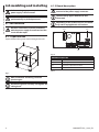
6 Assembling and installing
Before starting any operation, make sure the
power supply is disconnected.
The assembly and installation must be
performed only by skilled personnel.
6.1 Installation
Electrical connections must be performed
with the power supply disconnected and the
circuit-breaker open.
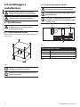
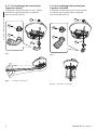
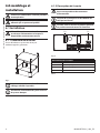
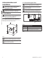
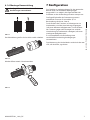
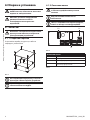
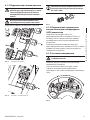
6.1.1 Open the box
Open the box taking care not to damage the seals.
Fig. 1
After installation and wiring, close the
product again.
Position the gaskets correctly and tighten the
cable glands.
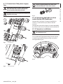
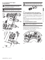
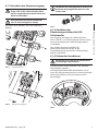
6.1.2 Board description
Connect the safety earth to the relative
terminal of the power supply connector.
The board may appear dierent to that
illustrated.
Depending on the product version, the board
may not be equipped with all functions.
P1F2
J5
Fig. 2
BOARD DESCRIPTION
Connector Function
J5 Day/Night status
P1 Sensitivity adjustment trimmer
F2 Fuse holder and fuse
Tab. 1

Instructions manual - English - EN
5MNVKUPTPSUL_1449_EN
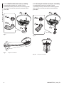
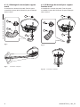
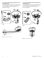
6.1.3 Connection of the power supply
line
Earth cable should be about 10mm longer
than the other two, so that it will not be
disconnected accidentally if pulled.
All signal cables must be grouped together
by means of a strap.
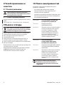
Connect the cables as shown in gure.
IN
OUT
a
24Vac
24Vac
a
N
L
Fig. 3 Standard box.
N
L
a
IN
Fig. 4 UL certied box.
Use the supplied gaskets for cables with
reduced diameters: From 3mm a 6mm.
Fig. 5
6.1.4 Connecting the light sensitive
switch for the LED illuminator
Connect the Day/Night (J5) output identied by
STATUS (+) to the alarm input (refer to the P&T
manual).
Connect the second Day/Night (J5) output identied
by STATUS to the alarms common terminal of the P&T.
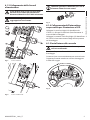
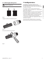
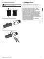
6.1.5 Connector installation
The operation is only to be carried out with
UL certied versions.
Access the lower part of the Pan & Tilt base.
Disassemble the highlighted cable gland to replace
it with the provided connector, taking care not to
damage the xing nut.
Fig. 6

EN - English - Instructions manual
6 MNVKUPTPSUL_1449_EN
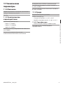
6.1.5.1 Wall bracket connector assembly
Assemble the junctions (01 and 02). Fix the
assembled junctions onto the base with the gasket
(03) and the nut of the previously removed cable
gland (04).
02
03
04
01
Fig. 7
Fig. 8 Complete installation.
6.1.5.2 Parapet bracket connector assembly
Assemble the junctions (01 and 02). Fix the
assembled junctions onto the base with the gasket
(03) and the nut of the previously removed cable
gland (04).
02
01
03
04
Fig. 9
Fig. 10 Complete installation.

Instructions manual - English - EN
7MNVKUPTPSUL_1449_EN
6.1.6 Sheath assembly
The operation is only to be carried out with
UL certied versions.
Straight cut of conduit.
Fig. 11
Push the silicone sheath completely into the
connector.
Fig. 12
To re-open use a screwdriver.
Fig. 13
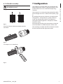
7 Configuration
The product has already been set in the factory for
optimal operation under a range of conditions. The
product features can be suited to the operating
situation.
Use trimmer P1 to adjust the intervention threshold
of the twilight sensor. (6.1.2 Board description, page
4).
By rotating the trimmer clockwise, the night mode
changeover is anticipated (at a greater luminous
value). By rotating the trimmer anti-clockwise,
the night mode changeover is delayed (at a lower
luminous value).
We recommend making the adjustments under the
actual conditions in which the spots will be used.
The switching on of the red LED on the board stands
for the activation of the night-time mode.

EN - English - Instructions manual
8 MNVKUPTPSUL_1449_EN
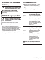
8 Maintaining and cleaning
8.1 Maintaining
Maintenance must be carried out by
personnel trained to operate on electrical
circuits.
8.1.1 Fuses replacement
The used fuse is described below.
T8A L 250 (F2, 6.1.2 Board description, page4).
9 Disposal of waste
materials
This symbol mark and recycle system are
applied only to EU countries and not applied
to the countries in the other area of the
world.
Your product is designed and manufactured with
high quality materials and components which can be
recycled and reused.
This symbol means that electrical and electronic
equipment, at their end-of-life, should be disposed of
separately from your household waste.
Please dispose of this equipment at your local
Community waste collection or Recycling centre.
In the European Union there are separate collection
systems for used electrical and electronic products.
10 Troubleshooting
Ask for assistance from skilled personnel if:
• The unit is damaged after being dropped;
• There is noticeable deterioration in performance
of the unit.
• The unit does not work properly, even though
all the instructions in this handbook have been
followed.
PROBLEM The unit does not power Pan &
Tilt.
CAUSE Fuses blown.
SOLUTION Make sure the power supply data
plate values coincide with the values
for the installation. Check that the
green LED inside the box is on. Make
sure there are no current overloads
or short circuits. Change the fuses.
PROBLEM The unit does not allow the
Day/Night changeover of the
P&T.
CAUSE Incorrect wiring or incorrect
trimmer regulation
SOLUTION Ensure that the board STATUS
contacts and the alarm contacts are
connected. Reset the twilight sensor
sensitivity.
If one of the problems listed persists, contact
the authorised service centre.

Instructions manual - English - EN
9MNVKUPTPSUL_1449_EN
11 Technical data
11.2 Mechanical
Box in aluminium, RAL7035 color
Dimensions: See drawing
Weight: 6kg (13.3lb)
11.3 Electrical
Power supply/Current consumption:
• 230Vac, 1A, 50/60Hz
• 120Vac, 1.7A, 50/60Hz
• 100Vac, 2A, 50/60Hz
Output voltage/Supplied current: 24Vac, 8A max,
50/60Hz
Built-in twilight sensor for automatic switching on
and o
Day/Night output (STATUS): Dry contact NO
Cables input section: From 3.3mm² (12 AWG) a
2.1mm² (14 AWG)
Cables signal section: From 0.52mm² (20 AWG) a
0.13mm² (26 AWG)
11.4 Environment
Indoor/Outdoor
Operating temperature
• Standard box: From -40°C (-40°F) a +60°C (140°F)
• UL certied box: From -40°C (-40°F) a +55°C
11.4.2 Certications
• IP protection degree: EN60529 (IP66)
UL certication: TYPE 4X (UL certied box)

MNVKUPTPSUL_1449_EN
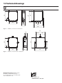
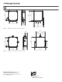
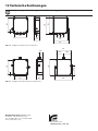
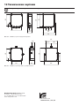
12 Technical drawings
The dimensions of the drawings are in millimetres.
196
90.5
54.5
226
253
9
217
50
239
278
50
Fig. 14 UPTIRPS, version of the standard box.
196 90.5
54.5
264
226
9
253
155
108.5 108.5
217
Fig. 15 UPTIRPS, version of the UL certied box.
Headquarters Italy Videotec S.p.A.
Via Friuli, 6 - I-36015 Schio (VI) - Italy
Tel. +39 0445 697411 - Fax +39 0445 697414
Email: [email protected]
www.videotec.com

Manuale di istruzioni - Italiano - IT
1MNVKUPTPSUL_1449_IT
ITALIANO
UPTIRPS
Scatola stagna per brandeggio con alimentatore e controllo degli
illuminatori
1 Informazioni sul presente
manuale
Prima di installare e utilizzare questa unità, leggere
attentamente questo manuale. Conservare questo
manuale a portata di mano come riferimento futuro.
1.1 Convenzioni tipograche
PERICOLO!
Pericolosità elevata.
Rischio di scosse elettriche. Prima di
eseguire qualsiasi operazione assicurarsi di
togliere tensione al prodotto, salvo diversa
indicazione.
ATTENZIONE!
Pericolosità media.
L'operazione è molto importante per il
corretto funzionamento del sistema. Si
prega di leggere attentamente la procedura
indicata e di eseguirla secondo le modalità
previste.
INFO
Descrizione delle caratteristiche del sistema.
Si consiglia di leggere attentamente per
comprendere le fasi successive.
2 Note sul copyright e
informazioni sui marchi
commerciali
I nomi di prodotto o di aziende citati sono marchi
commerciali o marchi commerciali registrati
appartenenti alle rispettive società.
3 Norme di sicurezza
ATTENZIONE! L'installazione e la
manutenzione del dispositivo deve
essere eseguita solo da personale tecnico
qualicato.
ATTENZIONE! L’impianto elettrico al quale
è collegata l’unità deve essere dotato di
un interruttore di protezione bipolare
automatico da 20A max. Tale interruttore
deve essere di tipo Listed. La distanza
minima tra i contatti deve essere di 3mm.
L’interruttore deve essere provvisto di
protezione contro la corrente di guasto
verso terra (dierenziale) e la sovracorrente
(magnetotermico).
• Il produttore declina ogni responsabilità per
eventuali danni derivanti da un uso improprio
delle apparecchiature menzionate in questo
manuale. Si riserva inoltre il diritto di modicarne il
contenuto senza preavviso. Ogni cura è stata posta
nella raccolta e nella verica della documentazione
contenuta in questo manuale. Il produttore,
tuttavia, non può assumersi alcuna responsabilità
derivante dall'utilizzo della stessa. Lo stesso
dicasi per ogni persona o società coinvolta nella
creazione e nella produzione di questo manuale.
• Prima di eseguire qualsiasi operazione assicurarsi
di togliere tensione al prodotto.
• Non utilizzare cavi con segni di usura o
invecchiamento.
• Non eettuare per nessun motivo alterazioni o
collegamenti non previsti in questo manuale.
L'uso di apparecchi non idonei può portare a
gravi pericoli per la sicurezza del personale e
dell'impianto.
• Utilizzare solo parti di ricambio originali. Pezzi di
ricambio non originali potrebbero causare incendi,
scariche elettriche o altri pericoli.

IT - Italiano - Manuale di istruzioni
2 MNVKUPTPSUL_1449_IT
• Prima di procedere con l'installazione, controllare
che il materiale fornito corrisponda alle speciche
richieste esaminando le etichette di marcatura (4.2
Marcatura del prodotto, pagina 3).
• La categoria di installazione (detta anche categoria
di sovratensione) specica i livelli della tensione
transitoria di rete alla quale l’apparato è soggetto.
La categoria dipende dal luogo di installazione
e dalla presenza di dispositivi di protezione
contro le sovratensioni. Un dispositivo per
ambienti industriali, connesso ai rami principali
dell’impianto di alimentazione è soggetto alla
categoria di installazione III. Se questo è il caso, è
richiesta una riduzione alla categoria II. Ciò può
essere ottenuto utilizzando un trasformatore
di isolamento con schermatura connessa a
terra tra il primario ed il secondario, o tramite
l’impiego di dispositivi di protezione contro le
sovratensioni (SPD), UL listed, connessi tra la fase
ed il neutro a tra il neutro e terra. I dispositivi SPD
UL listed, dovranno essere predisposti per limitare
sovratensioni transitorie in modo ripetitivo e per
la seguenti condizioni nominali di funzionamento:
Tipo 2 (Dispositivi SPD connessi permanentemente
alla rete di alimentazione, per istallazioni dal lato
del carico del dispositivo di servizio); Corrente
nominale di scarica (In) 20kA minimi. Si possono
utilizzare ad esempio: FERRAZ SHAWMUT,
ST23401PG-CN, ST240SPG-CN specicati per
120Vac/240Vac, (In=20kA). La distanza massima tra
l'installazione e la riduzione è di 5m.
• Questo dispositivo è stato progettato per essere
installato in maniera permanente su un edicio
o su una struttura adeguata. Il dispositivo deve
essere installato in maniera permanente prima di
eettuare qualsiasi operazione.
• Si devono rispettare le normative nazionali per
l'installazione del dispositivo.
• Un dispositivo di scollegamento, prontamente e
facilmente accessibile, deve essere incorporato
nell'impianto elettrico dell'edicio per un
intervento rapido.
• Il terminale di terra disponibile nel prodotto deve
essere collegato permanentemente alla terra.
• Per assicurare la protezione contro il rischio di
incendio, sostituire i fusibili con lo stesso tipo e
valore. I fusibili devono essere sostituiti solo da
personale qualicato.
• L'apparecchio è destinato all'installazione in
una Posizione ad Accesso Limitato eettuata da
personale tecnico qualicato.

Manuale di istruzioni - Italiano - IT
3MNVKUPTPSUL_1449_IT
4 Identificazione
4.1 Descrizione e designazione
del prodotto
Scatola stagna per brandeggio con alimentatore e
controllo degli illuminatori.
4.2 Marcatura del prodotto
Vedere l’etichetta posta sul prodotto.
5 Preparazione del
prodotto per l'utilizzo
Qualsiasi cambiamento non espressamente
approvato dal costruttore fa decadere la
garanzia.
5.3 Disimballaggio e contenuto
5.3.1 Disimballaggio
Alla consegna del prodotto vericare che l'imballo
sia integro e non abbia segni evidenti di cadute o
abrasioni.
In caso di evidenti segni di danno all'imballo
contattare immediatamente il fornitore.
Conservare l'imballo nel caso sia necessario inviare il
prodotto in riparazione.
5.3.2 Contenuto
Controllare che il contenuto sia corrispondente alla
lista del materiale sotto elencata:
• Scatola stagna
• Dotazione
• Manuale di istruzioni
5.4 Smaltimento in sicurezza dei
materiali di imballaggio
I materiali d'imballo sono costituiti interamente da
materiale riciclabile. Sarà cura del tecnico installatore
smaltirli secondo le modalità di raccolta dierenziata
o comunque secondo le norme vigenti nel Paese di
utilizzo.
In caso di restituzione del prodotto malfunzionante
è consigliato l'utilizzo dell'imballaggio originale per
il trasporto.

IT - Italiano - Manuale di istruzioni
4 MNVKUPTPSUL_1449_IT
6 Assemblaggio e
installazione
Prima di eseguire qualsiasi operazione
ricordarsi di togliere tensione al prodotto.
L'assemblaggio e l'installazione vanno
eseguiti solo da personale qualicato.
6.1 Installazione
Eseguire le connessioni elettriche in assenza
di alimentazione e con dispositivo di
sezionamento aperto.
6.1.1 Apertura della scatola
Aprire la scatola avendo cura di non danneggiare le
guarnizioni.
Fig. 1
Al termine delle operazioni di installazione e
cablaggio richiudere il prodotto.
Posizionare correttamente le guarnizioni e
serrare i pressacavi.
6.1.2 Descrizione della scheda
Collegare la terra di sicurezza al relativo
morsetto del connettore di alimentazione.
L'aspetto della scheda potrebbe dierire da
quello illlustrato.
La scheda, a seconda della versione del
prodotto, potrebbe non essere dotata di tutte
le funzionalità.
P1F2
J5
Fig. 2
DESCRIZIONE DELLA SCHEDA
Connettore Funzione
J5 Stato Day/Night
P1 Trimmer di regolazione della sensibilità
F2 Portafusibile e fusibile
Tab. 1

Manuale di istruzioni - Italiano - IT
5MNVKUPTPSUL_1449_IT
6.1.3 Collegamento della linea di
alimentazione
Il cavo di terra deve essere più lungo degli
altri due di circa 10mm per prevenirne il
distacco accidentale a causa dello stiramento.
Tutti i cavi di segnale devono essere
raggruppati con una fascetta.
Collegare i cavi come illustrato in gura.
IN
OUT
a
24Vac
24Vac
a
N
L
Fig. 3 Scatola standard.
N
L
a
IN
Fig. 4 Scatola certicata UL.
Utilizzare i gommini in dotazione per i cavi di
diametro ridotto: Da 3mm a 6mm.
Fig. 5
6.1.4 Collegamento dell’interruttore
crepuscolare per illuminatore a LED
Collegare l’uscita Day/Night (J5) identicata da
STATUS (+) all’ingresso d'allarme (fare riferimento al
manuale del brandeggio).
Collegare la seconda uscita Day/Night (J5) identicata
da STATUS al morsetto comune degli allarmi presenti
nel brandeggio.
6.1.5 Installazione del raccordo
L'operazione va eettuata solamente per le
versioni certicate UL.
Accedere alla parte inferiore della base del
brandeggio.
Smontare il pressacavo evidenziato per sostituirlo con
l’apposito raccordo avendo cura di non danneggiare
il dado di ssaggio.
Fig. 6

IT - Italiano - Manuale di istruzioni
6 MNVKUPTPSUL_1449_IT
6.1.5.1 Assemblaggio del raccordo per
supporto a parete
Assemblare i raccordi (01 e 02). Fissare i raccordi
assemblati, la guarnizione (03) e il dado del
pressacavo (04) alla base.
02
03
04
01
Fig. 7
Fig. 8 Installazione completata.
6.1.5.2 Assemblaggio del raccordo per
supporto a colonna
Assemblare i raccordi (01 e 02). Fissare i raccordi
assemblati, la guarnizione (03) e il dado del
pressacavo (04) alla base.
02
01
03
04
Fig. 9
Fig. 10 Installazione completata.

Manuale di istruzioni - Italiano - IT
7MNVKUPTPSUL_1449_IT
6.1.6 Montaggio della guaina
L'operazione va eettuata solamente per le
versioni certicate UL.
Tagliare la guaina trasversalmente.
Fig. 11
Spingere a fondo nel raccordo la guaina.
Fig. 12
Per riaprire utilizzare un cacciavite.
Fig. 13
7 Configurazione
Il prodotto è già regolato in fabbrica per il
funzionamento ottimale nelle varie condizioni. È
possibile adattare le caratteristiche del prodotto alla
situazione di impiego.
Per regolare la soglia di intervento del sensore
crepuscolare agire sul trimmer P1. (6.1.2 Descrizione
della scheda, pagina4).
Ruotando il trimmer in senso orario la commutazione
in modalità notturna è anticipata (ad un valore di
luminosità maggiore). Ruotando il trimmer in senso
antiorario la commutazione in modalità notturna è
ritardata (ad un valore di luminosità inferiore).
Si raccomanda di eettuare la regolazione nelle reali
condizioni di utilizzo.
L’attivazione della modalità notturna è segnalata
dall'accensione del LED rosso presente sulla scheda.

IT - Italiano - Manuale di istruzioni
8 MNVKUPTPSUL_1449_IT
8 Manutenzione e pulizia
8.1 Manutenzione
La manutenzione deve essere eseguita solo
da personale qualicato ad intervenire su
circuiti elettrici.
8.1.1 Sostituzione dei fusibili
Il fusibile utilizzato è descritto di seguito.
T8A L 250 (F2, 6.1.2 Descrizione della scheda, pagina
4).
9 Smaltimento dei rifiuti
Questo simbolo e il sistema di riciclaggio
sono validi solo nei paesi dell'EU e non
trovano applicazione in altri paesi del mondo.
Il vostro prodotto è costruito con materiali e
componenti di alta qualità, che sono riutilizzabili o
riciclabili.
Prodotti elettrici ed elettronici che riportano questo
simbolo, alla ne dell'uso, devono essere smaltiti
separatamente dai riuti casalinghi.
Vi preghiamo di smaltire questo apparecchio in un
Centro di raccolta o in un'Ecostazione.
Nell'Unione Europea esistono sistemi di raccolta
dierenziata per prodotti elettrici ed elettronici.
10 Troubleshooting
Richiedere l’intervento di personale qualicato
quando:
• L’unità si è danneggiata a seguito di una caduta;
• Le prestazioni dell’unità hanno avuto un evidente
peggioramento;
• L’unità non funziona correttamente anche se sono
state seguite tutte le indicazioni riportate nel
presente manuale.
PROBLEMA L'unità non alimenta il
brandeggio.
CAUSA Rottura dei fusibili.
SOLUZIONE Vericare i dati di targa
dell’alimentatore e la
corrispondenza ai dati dell’impianto.
Vericare che sia acceso il LED
verde all’interno della scatola.
Vericare l’assenza di sovraccarichi o
cortocircuiti. Sostituire i fusibili.
PROBLEMA L'unità non permette la
commutazione Day/Night del
brandeggio.
CAUSA Errato cablaggio o errata
regolazione del trimmer.
SOLUZIONE Assicurarsi che sia presente il
collegamento tra i contatti STATUS
della scheda e i contatti di allarme
del brandeggio. Reimpostare la
sensibilità del sensore crepuscolare.
Se uno qualunque dei problemi elencati
persiste, contattare il centro di assistenza
autorizzato.
Seite wird geladen ...
Seite wird geladen ...
Seite wird geladen ...
Seite wird geladen ...
Seite wird geladen ...
Seite wird geladen ...
Seite wird geladen ...
Seite wird geladen ...
Seite wird geladen ...
Seite wird geladen ...
Seite wird geladen ...
Seite wird geladen ...
Seite wird geladen ...
Seite wird geladen ...
Seite wird geladen ...
Seite wird geladen ...
Seite wird geladen ...
Seite wird geladen ...
Seite wird geladen ...
Seite wird geladen ...
Seite wird geladen ...
Seite wird geladen ...
Seite wird geladen ...
Seite wird geladen ...
Seite wird geladen ...
Seite wird geladen ...
Seite wird geladen ...
Seite wird geladen ...
Seite wird geladen ...
Seite wird geladen ...
Seite wird geladen ...
Seite wird geladen ...
Seite wird geladen ...
Seite wird geladen ...
-
 1
1
-
 2
2
-
 3
3
-
 4
4
-
 5
5
-
 6
6
-
 7
7
-
 8
8
-
 9
9
-
 10
10
-
 11
11
-
 12
12
-
 13
13
-
 14
14
-
 15
15
-
 16
16
-
 17
17
-
 18
18
-
 19
19
-
 20
20
-
 21
21
-
 22
22
-
 23
23
-
 24
24
-
 25
25
-
 26
26
-
 27
27
-
 28
28
-
 29
29
-
 30
30
-
 31
31
-
 32
32
-
 33
33
-
 34
34
-
 35
35
-
 36
36
-
 37
37
-
 38
38
-
 39
39
-
 40
40
-
 41
41
-
 42
42
-
 43
43
-
 44
44
-
 45
45
-
 46
46
-
 47
47
-
 48
48
-
 49
49
-
 50
50
-
 51
51
-
 52
52
-
 53
53
-
 54
54


Videotec UPTIRPS100N Benutzerhandbuch
- Typ
- Benutzerhandbuch
- Dieses Handbuch eignet sich auch für
in anderen Sprachen
- français: Videotec UPTIRPS100N Manuel utilisateur
- italiano: Videotec UPTIRPS100N Manuale utente
Verwandte Artikel
-
Videotec UPTIRPS Benutzerhandbuch
-
Videotec ULISSE RADICAL Benutzerhandbuch
-
-
Videotec ULISSE2 Benutzerhandbuch
-
Videotec ULISSE MAXI NETCAM Benutzerhandbuch
-
-
-
-
-