
DE
EN
Full Manual
LED Infrared Illuminator
IRLED-40xX

22
Inhalt
Inhalt ...........................................................................................................................2
Sicherheitshinweise .................................................................................................3
Warnungen ................................................................................................................3
Lieferumfang .............................................................................................................4
Montageoptionen .....................................................................................................5
Wandmontage ..........................................................................................................6
Decken- oder Brüstungsmontage .........................................................................7
Montage an einem Kameragehäuse ....................................................................8
Wandhalterungsmontage .......................................................................................9
Anschlüsse ............................................................................................................. 10
Rückseite ................................................................................................................ 11
Dämmerungsschalter Einstellung ...................................................................... 11
Weitere Informationen .......................................................................................... 11

3
DE
EN
FR
PL
RU
3
DE
EN
FR
PL
RU
Sicherheitshinweise
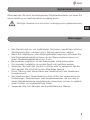
Bitte beachten Sie auch die beiliegenden Sicherheitshinweise und lesen Sie
diese Anleitung vor Inbetriebnahme sorgfältig durch.
Wichtige Hinweise sind mit einem Achtungsymbol gekennzeichnet.
Warnungen
• Das Produkt darf nur von qualifizierten Technikern, gemäß den örtlichen
Rechtsvorschriften, installiert und in Betrieb genommen werden.
• Bevor Sie Installations- oder Wartungsarbeiten beginnen, aktivieren Sie
alle Sicherheitsabschaltfunktionen an der Spannungsversorgung mit
einem Mindestkontaktabstand von 3 mm .
• Bei korrekter Installation ist der Scheinwerfer völlig wartungsfrei.
• Zur korrekten Installation muss das Gerät nicht geöffnet werden.
• Versuchen Sie nicht das Produkt zu öffnen oder zu reparieren. Bei Be-
darf, wenden Sie sich bitte an den After-Sales Service.
• Durch Öffnung oder Manipulation des Geräts erlischt der Gewährleis-
tungsanspruch.
• Das Gerät emittiert Infrarotstrahlung durch LEDs; die Verwendung von
Einstellungen, Regulierungen oder Vorgehensweisen, die von den, in
dieser Betriebsanleitung beschriebenen, abweichen, können zu gefährli-
chem Kontakt mit Infrarotstrahlung führen.
• Verwenden Sie zum Reinigen der Kunststoffteile nur Wasser.

44
Lieferumfang
• IRLED-40xX
• Betriebsanleitung
• L-Montagewinkel BWHYP1
• Befestigungsschrauben für BWHYP1
• 3-Pin Stromanschluss
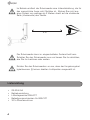
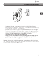
Im Betrieb emittiert der Scheinwerfer eine Infrarotstrahlung, die für
das menschliche Auge nicht Sichtbar ist. Blicken Sie nicht aus
einer Distanz von weniger als 2 Metern direkt auf die strahlende
Seite (Vorderseite) des Geräts.
Der Scheinwerfer kann im eingeschalteten Zustand heiß sein.
Schalten Sie den Scheinwerfer aus und lassen Sie ihn abkühlen,
ehe Sie ihn berühren oder warten.
Richten Sie den Scheinwerfern so aus, dass der Umgebungshel-
ligkeitssensor ② keinen direkten Lichtquellen ausgesetzt ist.
2 m

5
DE
EN
FR
PL
RU
5
DE
EN
FR
PL
RU
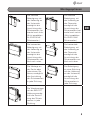
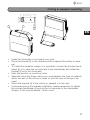
Montageoptionen
Die vertikale
Befestigung, mit
der Halterung an
der Unterseite,
ermöglicht die
Ausrichtung des
Scheinwerfers ho-
rizontal nach links.
(Nicht empfohlen
für IRLED-40xE
Scheinwerfer.)
Die vertikale
Befestigung, mit
der Halterung an
der Oberseite,
ermöglicht die
Ausrichtung des
Scheinwerfers hori-
zontal nach rechts.
(Nicht empfohlen
für IRLED-40xE
Scheinwerfer.)
Die horizontale
Befestigung, mit
der Halterung an
der Unterseite,
ermöglicht die
Ausrichtung des
Scheinwerfers ver-
tikal nach unten.
Die horizontale
Befestigung, mit
der Halterung an
der Oberseite,
ermöglicht die
Ausrichtung des
Scheinwerfers ver-
tikal nach oben.
Die Montage an
der Decke oder
unter einem Ge-
häuse, ermöglicht
die Ausrichtung
des Scheinwerfers
in jede Richtung.
Die Befestigung
an einer Brüstung,
mit der Halterung
an der Unterseite,
ermöglicht die
Ausrichtung des
Scheinwerfers in
jede Richtung.
Die Wandmontage
mit der BWHYP1
Halterung ermög-
licht die Ausrich-
tung des Schein-
werfers in jede
Richtung.

66
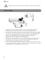
Wandmontage
Entfernen Sie die Schutzfolie der Abdeckung nach der Installation.
• Installieren Sie den Scheinwerfer in einem gut belüfteten Bereich.
• Verwenden Sie zur Mastmontage einen Mastmontageadapter.
• Bringen Sie die Halterung ⓐ in die gewünschte Position an der Wand.
• Um diesen Vorgang zu erleichtern, ist es möglich das gerändelte Stell-
rad ⓑ, oder gegebenenfalls die Mutter gegenüber des Stellrads, zu
lockern, und die Halterung ⓐ zum Scheinwerfer zu drehen.
• Markieren Sie die Position der Montagelöcher.
• Bohren Sie die Montagelöcher und berücksichtigen Sie dabei die Art
der Wand, sowie die des zu verwendenden Befestigungsmaterials.
• Montieren Sie die Halterung ⓐ fest an der Wand.
• Falls es während der Installation gelockert wurde, denken Sie bitte dar-
an das gerändelte Stellrad ⓑ und/oder die Mutter wieder fest zu ziehen
(Drehmoment: 4 Nm empfohlen / 8 Nm max.).
B
A
60
122.5
28
44
6,5
6,5

7
DE
EN
FR
PL
RU
7
DE
EN
FR
PL
RU
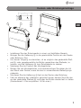
Decken- oder Brüstungsmontage
• Installieren Sie den Scheinwerfer in einem gut belüfteten Bereich.
• Bringen Sie die Halterung ⓐ in die gewünschte Position an der Decke
oder Brüstung. Das
• Um diesen Vorgang zu erleichtern, ist es möglich das gerändelte Stell-
rad ⓑ, oder gegebenenfalls die Mutter gegenüber des Stellrads, zu
lockern, und die Halterung ⓐ zum Scheinwerfer zu drehen.
• Markieren Sie die Position der Montagelöcher.
• Bohren Sie die Montagelöcher und berücksichtigen Sie dabei die Art
der Wand oder Decke, sowie die des zu verwendenden Befestigungs-
materials.
• Montieren Sie die Halterung ⓐ fest an der Decke oder Brüstung.
• Falls es während der Installation gelockert wurde, denken Sie bitte dar-
an das gerändelte Stellrad ⓑ und/oder die Mutter wieder fest zu ziehen
(Drehmoment: 4 Nm empfohlen / 8 Nm max.).
AB
60
28
44
6,5
6,5
122.5

88
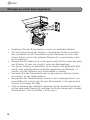
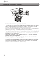
Montage an einem Kameragehäuse
• Installieren Sie den Scheinwerfer in einem gut belüfteten Bereich.
• Um die Positionierung der Muttern in der externen Schiene zu erleich-
tern, empfehlen wir die Verschraubung des Gehäuses zu lösen, den
Korpus öffnen und auf der externen Schiene ⓒ zu verschieben, ohne
ihn zu entfernen.
• Bringen Sie die Halterung ⓐ in die gewünschte Position unter der exter-
nen Schiene. ⓒ oder, wo möglich, unter der Gehäusebasis.
• Um diesen Vorgang zu erleichtern, ist es möglich das gerändelte Stell-
rad ⓑ, oder gegebenenfalls die Mutter gegenüber des Stellrads, zu
lockern, und die Halterung zum Scheinwerfer zu drehen.
• Montieren Sie den Scheinwerfer fest an der externen Schiene ⓒoder,
wo möglich, an der Gehäusebasis.
• Bringen Sie den Gehäusekorpus wieder in die Ausgangsposition und
verschließen ihn und bringen Sie den Scheinwerfer in die gewünschte
Position und fixieren Sie alles.
• Falls es während der Installation gelockert wurde, denken Sie bitte dar-
an das gerändelte Stellrad ⓑ und/oder die Mutter wieder fest zu ziehen
(Drehmoment: 4 Nm empfohlen / 8 Nm max.).
B
A
C

9
DE
EN
FR
PL
RU
9
DE
EN
FR
PL
RU
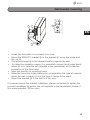
• Installieren Sie den Scheinwerfer in einem gut belüfteten Bereich.
• Montieren Sie die BWHYP1 Halterung ⓓ an der Scheinwerferhalterung
ⓐ mit Hilfe der Schraube und Mutter ⓔ.
• Bringen Sie die Halterung ⓓ in die gewünschte Position an der Wand.
• Um diesen Vorgang zu erleichtern, ist es möglich das gerändelte Stell-
rad ⓑ, oder gegebenenfalls die Mutter gegenüber des Stellrads, zu
lockern, und die Halterung zum Scheinwerfer zu drehen.
• Markieren Sie die Position der Montagelöcher.
• Bohren Sie die Montagelöcher und berücksichtigen Sie dabei die Art
der Wand, sowie die des zu verwendenden Befestigungsmaterials.
• Montieren Sie die Halterung ⓓ fest an der Wand.
Falls es während der Installation gelockert wurde, denken Sie bitte daran
das gerändelte Stellrad ⓑ und/oder die Mutter wieder fest zu ziehen (Dreh-
moment: 4 Nm empfohlen / 8 Nm max.).
D
A
E
28
44
60
105
6,5
6,5
D
Wandhalterungsmontage

1010
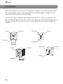
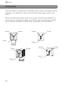
Anschlüsse
Der Scheinwerfer ist mit einem integrierten Netzteil und Dämmerungsschal-
ter ausgestattet; daher ist es ausreichend das Stromkabel einfach an die
Spannungsversorgung anzuschließen.
Achten Sie beim Auflegen des Kabels an den 3-Pin Anschlussstecker auf
die korrekte Belegung der Pins. Beim Anschluss an den Scheinwerfer muss
auf den richten Sitz der Dichtung und eine feste Verschraubung geachtet
werden.
PHASE
NEUTRAL
EARTH
PHASE
NEUTRA
L
EARTH
PHASE
NEUTRAL
EARTH
NEUTRAL
PHASE
EARTH
Leiter Nullleiter
Erdung
Leiter
Erdung
Nullleiter
Leiter
Erdung
Nullleiter
Leiter
Erdung
Nullleiter

11
DE
EN
FR
PL
RU
11
DE
EN
FR
PL
RU
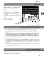
Weitere Sprachversionen dieser Anleitung sind auf der eneo Website unter
www.eneo-security.com verfügbar.
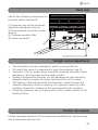
Weitere Informationen
Beschreibung der folgenden Kom-
ponenten auf der Rückseite des
Geräts:
① Schutzkappe für den Regler zur
Empfindlichkeitseinstellung der
Fotozelle
② Fenster des Umgebungslichtsen-
sors
③ Gleichdruckfilter
④ Stromanschluss
• Der Scheinwerfer ist werkseingestellt bei etwa 20 lux zu schalten.
• Um diesen Wert zu ändern ist es notwendig die Schutzkappe ① zu
öffnen.
• Stellen Sie mit einem 1x3mm Schraubendreher die Empfindlichkeit der
Fotozelle ein, welche den Scheinwerfer und Relaiskontakt schaltet.
• Durch drehen des Reglers in Uhrzeigerrichtung wird die Lichtempfind-
lichkeit verringert, während die Drehung gegen den Uhrzeigersinn die
Lichtempfindlichkeit erhöht.
• Das Aufleuchten der roten LED im Scheinwerfer, zu sehen durch die Zu-
gangsöffnung der Empfindlichkeitseinstellung, signalisiert das Erreichen
des Aktivierungsgrenzwerts im Verhältnis zu den Umgebungslichtver-
hältnissen.
• Schließen Sie die Schutzkappe ① unter Beachtung der richtigen Positi-
onierung des Dichtungsrings.
Dämmerungsschalter Einstellung
Rückseite
① ② ③
④

12
Contents
Contents ................................................................................................................. 12
Notes on safety ..................................................................................................... 13
Warnings ................................................................................................................. 13
Parts supplied ........................................................................................................ 14
Mounting options ................................................................................................. 15
Wall mounting ........................................................................................................ 16
Ceiling or parapet mounting ............................................................................... 17
Mounting to a camera housing .......................................................................... 18
Wall bracket mounting ......................................................................................... 19
Connections ........................................................................................................... 20
Back side ................................................................................................................ 21
Twilight control adjustment ................................................................................ 21
Further information .............................................................................................. 21

13
DE
EN
FR
PL
RU
Notes on safety
Please also pay attention to the enclosed safety instructions, and carefully
read through this instruction guide before initial operation.
Important points of advice are marked with a caution symbol.
Warnings
• The product must only be installed and used by qualified technicians, in
compliance with statutory regulations of the place where the product is
used.
• Before starting any installation or maintenance operations, activate all
safety cut-outs on the main supply with a contact breaker gap of at
least 3 mm.
• If properly installed, the illuminator is completely maintenance free.
• For a correct installation, it is not necessary to open the device.
• Do not try to open or repair the product; in case of need, contact after-
sales service.
• In case of opening or tampering of the device, warranty conditions will
be lost.
• The device gives out infrared radiation through LED; the use of controls,
regulations or proceedings, which are different from those stated in this
manual, can cause dangerous exposures to infrared radiation.
• To clean plastic parts, use only water.

14
Parts supplied
• IRLED-40xX
• Instruction manual
• L-Bracket BWHYP1
• Fixing screws for BWHYP1
• 3 pin power connector
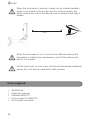
When the illuminator is working, it gives out an infrared radiation
which is not visible to the human eye. Do not look directly the
radiant side (front side of the device) from a distance less than 2
meters.
When the illuminator is on, it could be hot. Before touching the
illuminator or making any maintenance, turn off the device and
wait till it is cooled.
Put the illuminator in such a way that the environmental brightness
sensor ② is not directly exposed to light sources.
2 m

15
DE
EN
FR
PL
RU
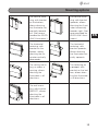
Mounting options
The vertical faste-
ning, with bracket
on the bottom,
allows directing
the illuminator ho-
rizontally towards
left. (Not recom-
mended for IRLED-
40xE illuminators.)
The vertical faste-
ning, with bracket
upwards, allows
directing the illumi-
nator horizontally
towards right. (Not
recommended for
IRLED-40xE illumi-
nators.)
The horizontal
fastening, with
bracket on the
bottom, allows
directing the illu-
minator vertically
downwards.
The horizontal
fastening, with
bracket upwards,
allows directing
the illuminator ver-
tically upwards.
The ceiling moun-
ting, or under a
housing, allows
directing the
illuminator in all
directions.
The fastening on
a parapet, with
bracket on the bot-
tom, allows direc-
ting the illuminator
in all directions.
The wall moun-
ting, with bracket
BWHYP1, allows
directing the
illuminator in all
directions.

16
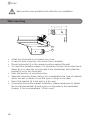
Wall mounting
Remove the cover protective film after the unit installation.
• Install the illuminator in a properly airy zone.
• In case of pole mounting, use a pole mount adapter.
• Place the bracket ⓐ in the desired position against the wall.
• To make this operation easier, it is possible to loosen the knurled hand-
wheel ⓑ or in case the nut opposite to the handwheel, and rotate the
bracket ⓐ as to the illuminator.
• Mark the position of mounting holes.
• Make the mounting holes, taking into consideration the type of material,
which the wall is made of, and the type of fixings to be used.
• Mount the bracket ⓐ to the wall in a firm way.
• If loosened during the bracket installation, please remember to tighten
the knurled handwheel ⓑ and/or the nut opposite to the handwheel
(torque: 4 Nm recommended / 8 Nm max.).
B
A
60
122.5
28
44
6,5
6,5

17
DE
EN
FR
PL
RU
Ceiling or parapet mounting
• Install the illuminator in a properly airy zone.
• Place the bracket ⓐ in the desired position against the ceiling or para-
pet.
• To make this operation easier, it is possible to loosen the knurled hand-
wheel ⓑ or in case the nut opposite to the handwheel, and rotate the
bracket ⓐ as to the illuminator.
• Mark the position of mounting holes.
• Make the mounting holes, taking into consideration the type of material,
which the wall or the ceiling is made of, and the type of fixings to be
used.
• Mount the bracket ⓐ to the ceiling or parapet in a firm way.
• If loosened during the bracket installation, please remember to tighten
the knurled handwheel ⓑ and/or the nut opposite to the handwheel
(torque: 4 Nm recommended / 8 Nm max.).
AB
60
28
44
6,5
6,5
122.5

18
Mounting to a camera housing
• Install the illuminator in a properly airy zone.
• To make the nuts positioning inside the external slide easier, we recom-
mend loosening the housing fastening screws, and sliding it on the
external slide ⓒ while keeping it hanging on the slide.
• Place the illuminator bracket ⓐ in the desired position, under the exter-
nal slide ⓒ or, where possible, under the housing basis.
• To make this operation easier, it is possible to loosen the knurled hand-
wheel ⓑ or in case the nut opposite to the handwheel, and rotate the
bracket as to the illuminator.
• Mount the illuminator to the external slide ⓒ in a firm way, or where
possible, at the housing basis.
• Place back and close the housing body, direct the illuminator in the
desired position, and fasten the whole.
• If loosened during the bracket installation, please remember to tighten
the knurled handwheel ⓑ and/or the nut opposite to the handwheel
(torque: 4 Nm recommended / 8 Nm max.).
B
A
C

19
DE
EN
FR
PL
RU
• Install the illuminator in a properly airy zone.
• Mount the BWHYP1 bracket ⓓ to the bracket ⓐ, using the screw and
the nut ⓔ.
• Place the bracket ⓓ in the desired position against the wall.
• To make this operation easier, it is possible to loosen the knurled hand-
wheel ⓑ or in case the nut opposite to the handwheel, and rotate the
bracket as to the illuminator.
• Mark the position of mounting holes.
• Make the mounting holes, taking into consideration the type of material,
which the wall is made of, and the type of fixings to be used.
• Mount the bracket ⓓ to the wall in a firm way.
If loosened during the bracket installation, please remember to tighten the
knurled handwheel ⓑ and/or the nut opposite to the handwheel (torque: 4
Nm recommended / 8 Nm max.).
D
A
E
28
44
60
105
6,5
6,5
D
Wall bracket mounting

20
Connections
The illuminator is provided with integrated power supply and twilight control;
therefore, it is sufficient to simply connect the power supply cable to the
main.
When connecting the cable to the 3 pin power connector pay attention to
the correct pin assignment. Make sure that the seal is positioned correctly
and connector screwed on tightly when connected to the illuminator.
PHASE
NEUTRAL
EARTH
PHASE
NEUTRA
L
EARTH
PHASE
NEUTRAL
EARTH
NEUTRAL
PHASE
EARTH
Phase Neutral
Earth
Phase
Earth
Neutral
Phase
Earth
Neutral
Phase
Earth
Neutral
Seite wird geladen ...
Seite wird geladen ...
Seite wird geladen ...
Seite wird geladen ...
-
 1
1
-
 2
2
-
 3
3
-
 4
4
-
 5
5
-
 6
6
-
 7
7
-
 8
8
-
 9
9
-
 10
10
-
 11
11
-
 12
12
-
 13
13
-
 14
14
-
 15
15
-
 16
16
-
 17
17
-
 18
18
-
 19
19
-
 20
20
-
 21
21
-
 22
22
-
 23
23
-
 24
24


in anderen Sprachen
- English: Eneo IRLED-40 Series
Andere Dokumente
-
Videotec ULISSE RADICAL Benutzerhandbuch
-
-
Videotec ULISSE MAXI NETCAM Benutzerhandbuch
-
Videotec ULISSE2 Benutzerhandbuch
-
Videotec GEKO IRH Benutzerhandbuch
-
-
-
-
-