
EN
English - Instruction manual
IT
Italiano - Manuale di istruzioni
FR
Français - Manuel d’instructions
DE
Deutsch - Bedienungsanleitung
RU
- Руководство по эксплуатации
ENGLISH
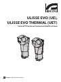
ULISSE EVO (UE),
ULISSE EVO THERMAL (UET)
PTZ camera with high performance and extreme reliability


EN
English - Instruction manual
ENGLISH
ULISSE EVO (UE),
ULISSE EVO THERMAL (UET)
PTZ camera with high performance and extreme reliability


Instruction manual - English - EN
3MNVCEVO_1947_EN
Contents
ENGLISH 1
1 About this manual ....................................................................................................................5
1.1 Typographical conventions ................................................................................................................................................ 5
2 Notes on copyright and information on trademarks .............................................................5
3 Safety rules................................................................................................................................5
4 Identication .............................................................................................................................8
4.1 Product Overview................................................................................................................................................................... 8
4.2 Product marking ..................................................................................................................................................................... 8
4.2.1 Checking the markings .......................................................................................................................................................................... 8
5 Versions .....................................................................................................................................9
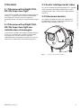
5.1 Day/Night FULL HD 30x Super low-light camera........................................................................................................ 9
5.2 Day/Night FULL HD 30x Super low-light camera with image stabilizer ............................................................. 9
5.3 Intelligent video analysis ..................................................................................................................................................... 9
5.4 Thermal camera ...................................................................................................................................................................... 9
6 Preparing the product for use ...............................................................................................10
6.1 Safety precautions before use .........................................................................................................................................10
6.2 Unpacking ...............................................................................................................................................................................10
6.3 Contents ..................................................................................................................................................................................10
6.4 Safely disposing of packaging material .......................................................................................................................10
6.5 Installation mode .................................................................................................................................................................11
6.5.1 Installation with internal cable passage ........................................................................................................................................11
6.5.2 Installation with internal cable passage with product overturned .....................................................................................12
6.5.3 Installation with quick connectors ..................................................................................................................................................13
6.5.4 Installation with quick connectors with product overturned ...............................................................................................14
6.6 Preparatory work before installation.............................................................................................................................15
6.6.1 Opening the base of the product ....................................................................................................................................................15
6.6.2 Mounting the bracket ..........................................................................................................................................................................15
6.6.3 Cables management.............................................................................................................................................................................16
6.6.4 Fixing the base to the support .......................................................................................................................................................... 17
6.6.5 Sunshield mounting .............................................................................................................................................................................17
6.6.6 Fastening of the safety coupling ......................................................................................................................................................17
7 Installation ..............................................................................................................................18
7.1 Connection of the connector board ..............................................................................................................................18
7.1.1 Connector board description ............................................................................................................................................................18
7.1.2 Connection of the power supply line (24Vac/24Vdc) ...............................................................................................................19
7.1.3 Alarm and relay connections .............................................................................................................................................................20
7.1.4 Connection of the Ethernet cable....................................................................................................................................................21
7.1.4.1 PoE 90W power supply ...............................................................................................................................................................................................21
7.1.5 Selecting the unit operating mode ................................................................................................................................................. 21
7.2 Installation of the upper body ......................................................................................................................................... 22
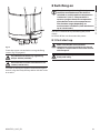
8 Switching on ...........................................................................................................................23
8.1 First start-up ...........................................................................................................................................................................23
9 Conguration .......................................................................................................................... 24

EN - English - Instruction manual
4 MNVCEVO_1947_EN
9.1 Default IP address.................................................................................................................................................................24
9.2 Web interface ......................................................................................................................................................................... 24
9.2.1 First access to the web pages ............................................................................................................................................................24
10 Accessories and Supports .................................................................................................... 24
10.1 LED illuminator ...................................................................................................................................................................24
10.2 Washer....................................................................................................................................................................................25
10.3 Power supply .......................................................................................................................................................................25
10.4 Wall mount bracket ...........................................................................................................................................................26
10.5 Parapet bracket ...................................................................................................................................................................26
10.6 Parapet bracket with quick connectors .....................................................................................................................26
10.7 Corner adaptor....................................................................................................................................................................26
10.8 Pole mount adaptor .......................................................................................................................................................... 27
10.9 Counter-plate ......................................................................................................................................................................27
11 Instructions for normal operation ......................................................................................27
12 Maintenance .........................................................................................................................28
12.1 Factory Default ...................................................................................................................................................................28
13 Cleaning ................................................................................................................................29
13.1 Cleaning the window and plastic parts .....................................................................................................................29
14 Information on disposal and recycling ...............................................................................29
15 Troubleshooting ...................................................................................................................29
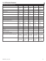
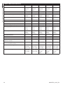
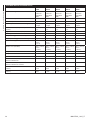
16 Technical data .......................................................................................................................30
16.1 General ..................................................................................................................................................................................30
16.2 Mechanical ...........................................................................................................................................................................30
16.3 Windows for camera .........................................................................................................................................................30
16.4 Electrical ................................................................................................................................................................................ 30
16.5 Network ................................................................................................................................................................................. 30
16.6 Cybersecurity .......................................................................................................................................................................31
16.7 Video for Day/Night camera ...........................................................................................................................................31
16.8 Video for Thermal camera ............................................................................................................................................... 31
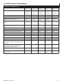
16.9 Day/Night cameras ............................................................................................................................................................32
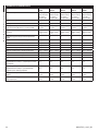
16.10 Thermal Cameras ............................................................................................................................................................. 33
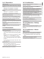
16.11 Illuminators ........................................................................................................................................................................35
16.12 Environment ......................................................................................................................................................................35
16.13 Certications .....................................................................................................................................................................35
16.14 Certications - Railway applications .........................................................................................................................35
16.15 Certications - Marine applications .......................................................................................................................... 35
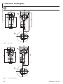
17 Technical drawings ...............................................................................................................36

Instruction manual - English - EN
5MNVCEVO_1947_EN
1 About this manual
Read all the documentation supplied carefully before
installing and using this product. Keep the manual in
a convenient place for future reference.
1.1 Typographical conventions
DANGER!
High level hazard.
Risk of electric shock. Disconnect the
power supply before proceeding with any
operation, unless indicated otherwise.
DANGER!
Mechanical hazard.
Risk of crushing or shearing.
CAUTION!
Medium level hazard.
This operation is very important for the
system to function properly. Please read
the procedure described very carefully and
carry it out as instructed.
INFO
Description of system specications.
We recommend reading this part carefully
in order to understand the subsequent
stages.
2 Notes on copyright and
information on trademarks
The mentioned names of products or companies are
trademarks or registered trademarks.
Microsoft Edge®, Windows XP®, Windows Vista®,
Windows 7®, Windows 8®, Windows 10® are the
property of Microsoft Corporation.
INTEL® Core™ 2 Duo, INTEL® Core™ 2 Quad, INTEL®
Xeon® are the property of Intel Corporation.
ONVIF® is a trademark of Onvif, Inc.
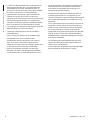
3 Safety rules
CAUTION! Hazardous moving parts. Keep
ngers and other body parts away.
CAUTION! Device installation and
maintaining must be performed by
specialist technical sta only.
CAUTION! TNV-1 installation type. The
installation is type TNV-1, do not connect it
to SELV circuits.
CAUTION! In order to reduce the risk of re,
only use UL Listed or CSA certied cables
with sections greater than or equal to
0.14mm² (26AWG).
CAUTION! The infrared LED illuminator
emits high-intensity visible light. For
further details on conguration and use,
refer to the relative accessory manual.
CAUTION! The white LED illuminator emits
high intensity light. For further details on
conguration and use, refer to the relative
accessory manual.
During normal operation the surface of the
illuminator can reach high temperatures.
Do not allow direct contact and position
the appliance where it is inaccessible to
unauthorised persons. Before touching
switch o the illuminator and allow to cool
for a minimum period of 10 minutes.

EN - English - Instruction manual
6 MNVCEVO_1947_EN
• The manufacturer declines all responsibility
for any damage caused by an improper use
of the appliances mentioned in this manual.
Furthermore, the manufacturer reserves the right
to modify its contents without any prior notice.
The documentation contained in this manual has
been collected and veried with great care. The
manufacturer, however, cannot take any liability
for its use. The same thing can be said for any
person or company involved in the creation and
production of this manual.
• Equipment intended for installation in Restricted
Access Location performed by specialist technical
sta.
• Before starting any operation, make sure the
power supply is disconnected.
• Be careful not to use cables that seem worn or old.
• Never, under any circumstances, make any
changes or connections that are not shown in
this handbook. Improper use of the appliance
can cause serious hazards, risking the safety of
personnel and of the installation.
• Use only original spare parts. Non-original spare
parts could cause re, electrical discharge or other
hazards.
• Before proceeding with installation, check the
supplied material to make sure it corresponds
to the order specication by examining the
identication labels (4.2 Product marking, page 8).
• This device was designed to be permanently
secured and connected on a building or on a
suitable structure. The device must be permanently
secured and connected before any operation.
• Use a Class 2 listed UL tranformer, compliant with
the Standards in force, only for products marked
UL, powered at 24Vac.
• In the case of a 24Vac power supply, you must
provide for adequate separation from the AC
power supply line using double or reinforced
insulation between the main power supply line
and the secondary circuit.
• A power disconnect device must be included
in the electrical installation, and it must be very
quickly recognizable and operated if needed.
• The separate protective earthing terminal provided
on this product shall be permanently connected
to earth.

Instruction manual - English - EN
7MNVCEVO_1947_EN
• This is a Class A product. In a domestic
environment this product may cause radio
interference. In this case the user may be required
to take adequate measures.
• Connect the device to a power source
corresponding to the indications given on the
marking label. Before proceeding with installation
make sure that the power line is properly isolated.
The power supply voltage must not exceed the
limits: 24Vac ±20%, 24Vdc ±10%.
• If it is necessary to transport the device, this should
be done with great care. Abrupt stops, bumps and
violent impact could damage the unit or injure the
user.
• To comply with the main supply voltage dips and
short interruption requirements, use a suitable
Uninterruptable Power Supply (UPS) to power the
unit.
• The appliance includes moving parts. Make sure
that the unit is positioned where it is inaccessible
under normal operating conditions.
• Attach the Dangerous Moving Parts label near the
device. (Fig. 4, page10).
• Do not use the appliance in the presence of
inammable substances.
• Do not allow children or unauthorised people to
use the appliance.
• The device can only be considered to be switched
o when the power supply has been disconnected
and the connection cables to other devices have
been removed.
• Only skilled personnel should carry out
maintenance on the device. When carrying out
maintenance, the operator is exposed to the risk of
electrocution and other hazards.
• Use only the accessories indicated by the
manufacturer. Any change that is not expressly
approved by the manufacturer will invalidate the
guarantee.
• Take all necessary precautions to prevent the
apparatus from being damaged by electrostatic
discharge.
• The unit has been made for connection using a
3-pole cable. To make a correct connection to
the earth circuit, follow the instructions in this
handbook.
• Handle the unit with great care, high mechanical
stress could damage it.

EN - English - Instruction manual
8 MNVCEVO_1947_EN
4 Identication
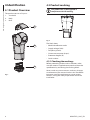
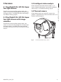
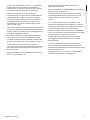
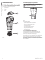
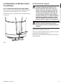
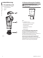
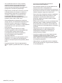
4.1 Product Overview
The product consists of 3 parts:
1. Sunshield.
2. Body.
3. Base.
01
02
03
Fig. 1
4.2 Product marking
The product has a label applied in
compliance with CE marking.
Fig. 2
The label shows:
• Model identication code.
• Supply voltage (Volt).
• Frequency (Hertz).
• Current consumption (Amps).
• Protection degree (IP).
• Serial number.
4.2.1 Checking the markings
Before proceeding further with installation, make
sure the material supplied corresponds to the order
specication by examining the marking labels.
Never, under any circumstances, make any changes
or connections that are not shown in this handbook.
Improper use of the appliance can cause serious
hazards, risking the safety of personnel and of the
installation.

Instruction manual - English - EN
9MNVCEVO_1947_EN
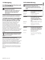
5 Versions
5.1 Day/Night FULL HD 30x Super
low-light camera
If the fourth character of the product code is the
value "1", it means the Day/Night FULL HD 30x Super
low-light camera is installed with Delux technology (
4.2 Product marking, page8).
5.2 Day/Night FULL HD 30x Super
low-light camera with image
stabilizer
If the fourth character of the product code is the
value "2", it means the Day/Night FULL HD 30x Super
low-light camera is installed with image stabilizer
and masks for dynamic privacy (4.2 Product marking,
page8).
5.3 Intelligent video analysis
If the sixth character of the product code is "V", it
means Videotec technology is present for intelligent
video analysis. (4.2 Product marking, page8).
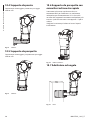
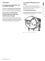
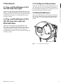
5.4 Thermal camera
If the product code starts with UET, it means the
product is equipped with a thermal video camera (4.2
Product marking, page8).
Fig. 3 Version with thermal video camera

EN - English - Instruction manual
10 MNVCEVO_1947_EN
6 Preparing the product for
use
Any change that is not expressly approved
by the manufacturer will invalidate the
guarantee.
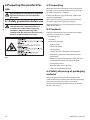
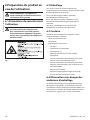
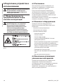
6.1 Safety precautions before use
The appliance includes moving parts. Make
sure that the unit is positioned where it
is inaccessible under normal operating
conditions. Attach the warning label
supplied with the appliance, placing it near
the unit so that it can be seen easily.
Fig. 4
6.2 Unpacking
When the product is delivered, make sure that the
package is intact and that there are no signs that it
has been dropped or scratched.
If there are obvious signs of damage, contact the
supplier immediately.
When returning a faulty product we recommend
using the original packaging for shipping.
Keep the packaging in case you need to send the
product for repairs.
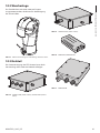
6.3 Contents
Check the contents to make sure they correspond
with the list of materials as below:
• Positioning unit
• Sunshield
• Accessories package:
• Allen wrench
• Power connector
• I/O connector
• Label (CAUTION: Hazardous moving parts)
• Reduction gasket, for alarm cable, for cable
glands M16
• Reduction gasket, for Ethernet cable, with pre-
assembled connector, for connector M20
• Instruction manual
• Plate for safety chain coupling
• Screw for sunshield fastening
6.4 Safely disposing of packaging
material
The packaging material can all be recycled. The
installer technician will be responsible for separating
the material for disposal, and in any case for
compliance with the legislation in force where the
device is to be used.

Instruction manual - English - EN
11MNVCEVO_1947_EN
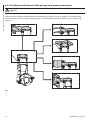
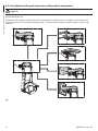
6.5 Installation mode
The product can be installed in various modes using the supports and various adaptors available, meeting every
installation requirement.
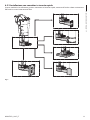
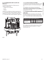
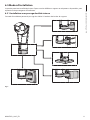
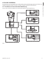
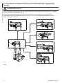
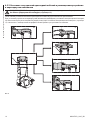
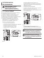
6.5.1 Installation with internal cable passage
This installation mode allows cable passage inside the mounting brackets.
D
E
C
F
B
A
Fig. 5

EN - English - Instruction manual
12 MNVCEVO_1947_EN
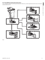
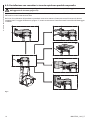
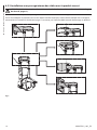
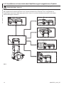
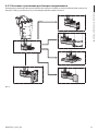
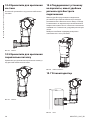
6.5.2 Installation with internal cable passage with product overturned
CAUTION! Always secure the product with the safety chain (6.6.6 Fastening of the safety coupling,
page17).
This installation mode allows cable passage inside the mounting brackets.
In the event of installation of the product overturned, the sunshield must be assembled as illustrated in the
relevant chapter (6.6.5 Sunshield mounting, page17) and enable the Ceiling Assembly mode using the web
interface.
D
E
C
F
B
A
Fig. 6

Instruction manual - English - EN
13MNVCEVO_1947_EN
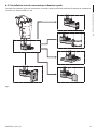
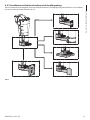
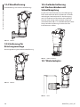
6.5.3 Installation with quick connectors
This installation mode thanks to the quick connectors allows easy and fast replacement of the unit in the event
of intervention on site.
D
E
C
F
B
A
Fig. 7

EN - English - Instruction manual
14 MNVCEVO_1947_EN
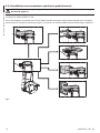
6.5.4 Installation with quick connectors with product overturned
CAUTION! Always secure the product with the safety chain (6.6.6 Fastening of the safety coupling,
page17).
This installation mode thanks to the quick connectors allows easy and fast replacement of the unit in the event
of intervention on site.
In the event of installation of the product overturned, the sunshield must be assembled as illustrated in the
relevant chapter (6.6.5 Sunshield mounting, page17) and enable the Ceiling Assembly mode using the web
interface.
D
E
C
F
B
A
Fig. 8

Instruction manual - English - EN
15MNVCEVO_1947_EN
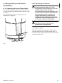
6.6 Preparatory work before
installation
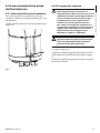
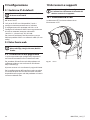
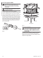
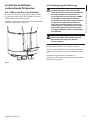
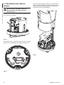
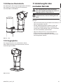
6.6.1 Opening the base of the product
To avoid scratching the product with the hexagonal
wrench, align the body of the product with the screw
to remove.
Unscrew the three screws at the bottom of the
product (Fig. 9, page15).
Fig. 9
6.6.2 Mounting the bracket
Take special care when attaching and
fastening down the apparatus. If the
equipment must be fastened to a concrete
surface, plugs must be used with a
minimum traction force of 300dN each. For
a metal surface use screws with a diameter
of at least 8mm and of an appropriate
length. The fastening system must be
capable of supporting at least 4 times the
weight of the entire equipment (pan & tilt,
lens, camera, supports and adapters).
The device should be assembled vertically.
Any other position could impair the
performance of the appliance.
Various types of support are available (10 Accessories
and Supports, page24).
Choose the adequate support for installation you
want to implement (6.5 Installation mode, page11).
Install the support following the instructions outlined
in the relevant manual.

EN - English - Instruction manual
16 MNVCEVO_1947_EN
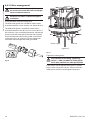
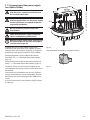
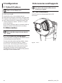
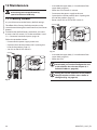
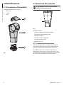
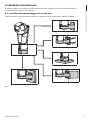
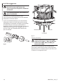
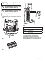
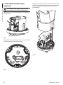
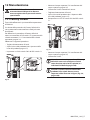
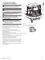
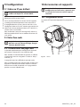
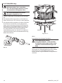
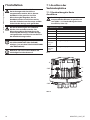
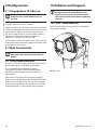
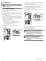
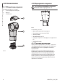
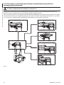
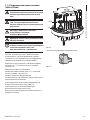
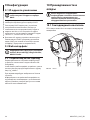
6.6.3 Cables management
The cables must be adequately fastened to
the structure to avoid the excessive weight
causes accidental removal.
You must use cables suited to the type of
installation.
Insert the cables into the cable glands.
The M16 cable glands are suitable for cables with a
diameter between 4.5mm (0.18in) and 10mm (0.39in).
The M20 cable gland is suitable for cables with a
diameter between 8mm (0.31in) and 13mm (0.5in). If
the cable has a pre-assembled connector, replace the
gasket inside the cable gland with the one supplied.
Insert the Ethernet cable in the gasket as illustrated
in the gure (Fig. 10, page16). Pass the cable with
connector RJ45 through the cable gland M20.
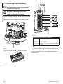
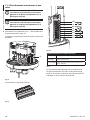
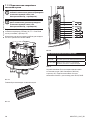
Fig. 10
M20
M16
M16
Power supply
Digital I/O
Ethernet
Fig. 11
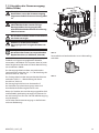
Tighten the cable glands.
Pay attention to the xing. Tightening
torque : 1.5Nm (±0.2Nm) for cable glands
M16, 2Nm (±0.2Nm) for cable glands M20.
If the cable is not inside the cable gland, a specic
cap must be inserted for closure. Always close the
cable glands with the stated tightening torque.

Instruction manual - English - EN
17MNVCEVO_1947_EN
6.6.4 Fixing the base to the support
For further details on conguration and
use, refer to the manual of the relevant
accessory or support.
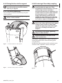
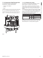
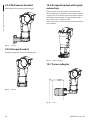
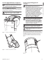
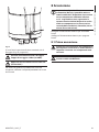
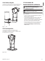
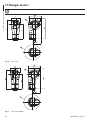
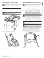
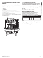
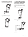
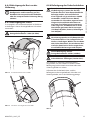
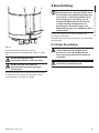
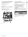
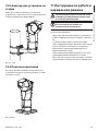
6.6.5 Sunshield mounting
You can x the sunshield to the housing using the
screws supplied.
Pay attention to the xing. Tightening
torque: 1.6Nm (±0.2Nm).
Fig. 12 Standard installation of the product.
Fig. 13 Installation of the product overturned.
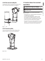
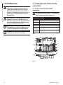
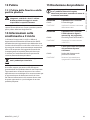
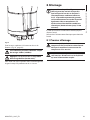
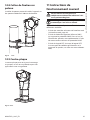
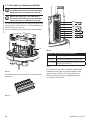
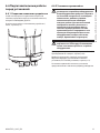
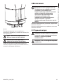
6.6.6 Fastening of the safety coupling
Take special care when attaching and
fastening down the apparatus. If the
equipment must be fastened to a concrete
surface, plugs must be used with a
minimum traction force of 300dN each. For
a metal surface use screws with a diameter
of at least 8mm and of an appropriate
length. The fastening system must be
capable of supporting at least 4 times the
weight of the entire equipment (pan & tilt,
lens, camera, supports and adapters).
Use an external anchor point to x the
chain or the safety cable to the unit support
surface. Choose a chain or safety cable
capable of supporting 4 times the weight
of the unit, including its brackets and
adaptors.
Pay attention to the xing. Tightening
torque: 4.5Nm (±0.2Nm).
Apply threadlocker in the holes of the
screws (Loctite 243®).
The product is equipped with a safety coupling to
secure the product and a second fastening point
using the chain.
Position the safety coupling and x it with the screw
and the washer supplied as shown in the gure.
Fig. 14

EN - English - Instruction manual
18 MNVCEVO_1947_EN
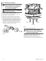
7 Installation
Never, under any circumstances, make
any changes or connections that are not
shown in this handbook. Failure to follow
the connection instructions that are given
in the handbook may create serious safety
hazards for people and for the installation.
Do not change the wiring in the product
as it is supplied to you. Failure to follow
this instruction may create serious safety
hazards for people and for the installation,
and will also invalidate the guarantee.
The product can be powered in
24Vac/24Vdc or via PoE 90W (only with
OHEP90INJ or OHEP90INJO accessories).
Keep the connection diagram for future
reference.
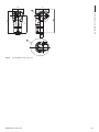
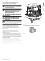
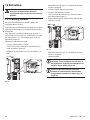
7.1 Connection of the connector
board
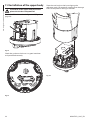
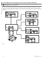
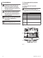
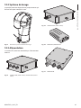
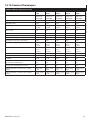
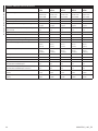
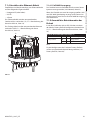
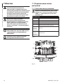
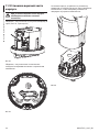
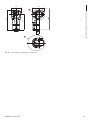
7.1.1 Connector board description
The ground cable must always be
connected to the relevant terminal (GND,
7.1.1 Connector board description, page
18).
BOARD DESCRIPTION
Connector Function
J3 Ethernet
J4 Power supply
J6 Digital I/O
S1 Selecting the unit operating mode
GND (internal
ground
terminal)
Ground connection, 24Vac/dc power supply
GND (external
ground
terminal)
Ground connection, power supply in PoE90W
Tab. 1
J4
GND
GND
S1
J6
J3
Fig. 15
Seite wird geladen ...
Seite wird geladen ...
Seite wird geladen ...
Seite wird geladen ...
Seite wird geladen ...
Seite wird geladen ...
Seite wird geladen ...
Seite wird geladen ...
Seite wird geladen ...
Seite wird geladen ...
Seite wird geladen ...
Seite wird geladen ...
Seite wird geladen ...
Seite wird geladen ...
Seite wird geladen ...
Seite wird geladen ...
Seite wird geladen ...
Seite wird geladen ...
Seite wird geladen ...
Seite wird geladen ...
Seite wird geladen ...
Seite wird geladen ...
Seite wird geladen ...
Seite wird geladen ...
Seite wird geladen ...
Seite wird geladen ...
Seite wird geladen ...
Seite wird geladen ...
Seite wird geladen ...
Seite wird geladen ...
Seite wird geladen ...
Seite wird geladen ...
Seite wird geladen ...
Seite wird geladen ...
Seite wird geladen ...
Seite wird geladen ...
Seite wird geladen ...
Seite wird geladen ...
Seite wird geladen ...
Seite wird geladen ...
Seite wird geladen ...
Seite wird geladen ...
Seite wird geladen ...
Seite wird geladen ...
Seite wird geladen ...
Seite wird geladen ...
Seite wird geladen ...
Seite wird geladen ...
Seite wird geladen ...
Seite wird geladen ...
Seite wird geladen ...
Seite wird geladen ...
Seite wird geladen ...
Seite wird geladen ...
Seite wird geladen ...
Seite wird geladen ...
Seite wird geladen ...
Seite wird geladen ...
Seite wird geladen ...
Seite wird geladen ...
Seite wird geladen ...
Seite wird geladen ...
Seite wird geladen ...
Seite wird geladen ...
Seite wird geladen ...
Seite wird geladen ...
Seite wird geladen ...
Seite wird geladen ...
Seite wird geladen ...
Seite wird geladen ...
Seite wird geladen ...
Seite wird geladen ...
Seite wird geladen ...
Seite wird geladen ...
Seite wird geladen ...
Seite wird geladen ...
Seite wird geladen ...
Seite wird geladen ...
Seite wird geladen ...
Seite wird geladen ...
Seite wird geladen ...
Seite wird geladen ...
Seite wird geladen ...
Seite wird geladen ...
Seite wird geladen ...
Seite wird geladen ...
Seite wird geladen ...
Seite wird geladen ...
Seite wird geladen ...
Seite wird geladen ...
Seite wird geladen ...
Seite wird geladen ...
Seite wird geladen ...
Seite wird geladen ...
Seite wird geladen ...
Seite wird geladen ...
Seite wird geladen ...
Seite wird geladen ...
Seite wird geladen ...
Seite wird geladen ...
Seite wird geladen ...
Seite wird geladen ...
Seite wird geladen ...
Seite wird geladen ...
Seite wird geladen ...
Seite wird geladen ...
Seite wird geladen ...
Seite wird geladen ...
Seite wird geladen ...
Seite wird geladen ...
Seite wird geladen ...
Seite wird geladen ...
Seite wird geladen ...
Seite wird geladen ...
Seite wird geladen ...
Seite wird geladen ...
Seite wird geladen ...
Seite wird geladen ...
Seite wird geladen ...
Seite wird geladen ...
Seite wird geladen ...
Seite wird geladen ...
Seite wird geladen ...
Seite wird geladen ...
Seite wird geladen ...
Seite wird geladen ...
Seite wird geladen ...
Seite wird geladen ...
Seite wird geladen ...
Seite wird geladen ...
Seite wird geladen ...
Seite wird geladen ...
Seite wird geladen ...
Seite wird geladen ...
Seite wird geladen ...
Seite wird geladen ...
Seite wird geladen ...
Seite wird geladen ...
Seite wird geladen ...
Seite wird geladen ...
Seite wird geladen ...
Seite wird geladen ...
Seite wird geladen ...
Seite wird geladen ...
Seite wird geladen ...
Seite wird geladen ...
Seite wird geladen ...
Seite wird geladen ...
Seite wird geladen ...
Seite wird geladen ...
Seite wird geladen ...
Seite wird geladen ...
Seite wird geladen ...
Seite wird geladen ...
Seite wird geladen ...
Seite wird geladen ...
Seite wird geladen ...
Seite wird geladen ...
Seite wird geladen ...
Seite wird geladen ...
Seite wird geladen ...
Seite wird geladen ...
Seite wird geladen ...
Seite wird geladen ...
Seite wird geladen ...
Seite wird geladen ...
Seite wird geladen ...
Seite wird geladen ...
Seite wird geladen ...
Seite wird geladen ...
Seite wird geladen ...
Seite wird geladen ...
Seite wird geladen ...
Seite wird geladen ...
-
 1
1
-
 2
2
-
 3
3
-
 4
4
-
 5
5
-
 6
6
-
 7
7
-
 8
8
-
 9
9
-
 10
10
-
 11
11
-
 12
12
-
 13
13
-
 14
14
-
 15
15
-
 16
16
-
 17
17
-
 18
18
-
 19
19
-
 20
20
-
 21
21
-
 22
22
-
 23
23
-
 24
24
-
 25
25
-
 26
26
-
 27
27
-
 28
28
-
 29
29
-
 30
30
-
 31
31
-
 32
32
-
 33
33
-
 34
34
-
 35
35
-
 36
36
-
 37
37
-
 38
38
-
 39
39
-
 40
40
-
 41
41
-
 42
42
-
 43
43
-
 44
44
-
 45
45
-
 46
46
-
 47
47
-
 48
48
-
 49
49
-
 50
50
-
 51
51
-
 52
52
-
 53
53
-
 54
54
-
 55
55
-
 56
56
-
 57
57
-
 58
58
-
 59
59
-
 60
60
-
 61
61
-
 62
62
-
 63
63
-
 64
64
-
 65
65
-
 66
66
-
 67
67
-
 68
68
-
 69
69
-
 70
70
-
 71
71
-
 72
72
-
 73
73
-
 74
74
-
 75
75
-
 76
76
-
 77
77
-
 78
78
-
 79
79
-
 80
80
-
 81
81
-
 82
82
-
 83
83
-
 84
84
-
 85
85
-
 86
86
-
 87
87
-
 88
88
-
 89
89
-
 90
90
-
 91
91
-
 92
92
-
 93
93
-
 94
94
-
 95
95
-
 96
96
-
 97
97
-
 98
98
-
 99
99
-
 100
100
-
 101
101
-
 102
102
-
 103
103
-
 104
104
-
 105
105
-
 106
106
-
 107
107
-
 108
108
-
 109
109
-
 110
110
-
 111
111
-
 112
112
-
 113
113
-
 114
114
-
 115
115
-
 116
116
-
 117
117
-
 118
118
-
 119
119
-
 120
120
-
 121
121
-
 122
122
-
 123
123
-
 124
124
-
 125
125
-
 126
126
-
 127
127
-
 128
128
-
 129
129
-
 130
130
-
 131
131
-
 132
132
-
 133
133
-
 134
134
-
 135
135
-
 136
136
-
 137
137
-
 138
138
-
 139
139
-
 140
140
-
 141
141
-
 142
142
-
 143
143
-
 144
144
-
 145
145
-
 146
146
-
 147
147
-
 148
148
-
 149
149
-
 150
150
-
 151
151
-
 152
152
-
 153
153
-
 154
154
-
 155
155
-
 156
156
-
 157
157
-
 158
158
-
 159
159
-
 160
160
-
 161
161
-
 162
162
-
 163
163
-
 164
164
-
 165
165
-
 166
166
-
 167
167
-
 168
168
-
 169
169
-
 170
170
-
 171
171
-
 172
172
-
 173
173
-
 174
174
-
 175
175
-
 176
176
-
 177
177
-
 178
178
-
 179
179
-
 180
180
-
 181
181
-
 182
182
-
 183
183
-
 184
184
-
 185
185
-
 186
186
-
 187
187
-
 188
188
-
 189
189
-
 190
190
-
 191
191
-
 192
192
-
 193
193
-
 194
194


Videotec ULISSE EVO Benutzerhandbuch
- Typ
- Benutzerhandbuch
- Dieses Handbuch eignet sich auch für
in anderen Sprachen
- français: Videotec ULISSE EVO Manuel utilisateur
- italiano: Videotec ULISSE EVO Manuale utente
Verwandte Artikel
-
Videotec UEBP0 Benutzerhandbuch
-
-
-
-
-
Videotec ULISSE RADICAL Benutzerhandbuch
-
-
Videotec UEBW Benutzerhandbuch
-
-