
2116/2132
PID temperature controllers
User Guide
Manuel Utilisateur
Bedienungsanleitung
ENG
FRA
GER

This booklet includes:
User Guide (HA026270 Issue 5)
Manuel Utilisateur (HA026270FRA Indice 5)
Bedienungsanleitung (HA026270GER Ausgabe 5)

Part Number HA026270 Issue 5.0 Aug 07 1
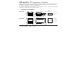
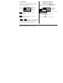
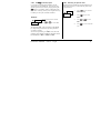
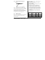
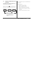
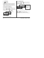
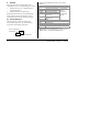
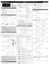
2132 and 2116 PID Temperature Controllers
Thank you for choosing the 2132 or 2116 Temperature Controller. Supplied in 1/32 and 1/16 DIN panel sizes they
are designed for accurate, stable control of ovens, chillers, sterilisers and other heating and cooling processes.
Two outputs are configurable for heating, cooling and alarms.
The controller is supplied configured according to the order code given in section 5. Check this on the side labels
to determine the configuration of your particular controller.
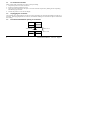
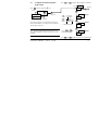
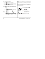
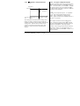
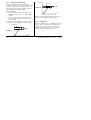
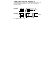
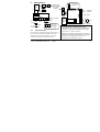
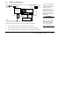
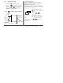
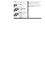
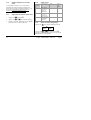
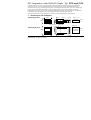
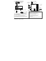
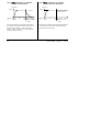
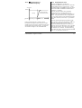
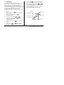
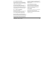
1. Dimensions and Installation
Model 2132
Model 2116
48mm (1.89in)
45 x 45 mm
-0.0, + 0.6
1.77 x 1.77in
-0.00, +0.02
48mm
Panel cut-out
24mm
103mm (4.01in)
45mm
-0.0, +0.6
1.77in
-0.0, +0.02
Latching ears
Panel retaining clips
22mm
-0.0, +0.3
0.88in
-0.0, +0.10
Panel cut-out
103mm (4.01in)
48mm (1.89in)
Seite wird geladen ...
Seite wird geladen ...
Seite wird geladen ...
Seite wird geladen ...
Seite wird geladen ...
Seite wird geladen ...
Seite wird geladen ...
Seite wird geladen ...

10 Part Number HA026270 Issue 5.0 Aug 07
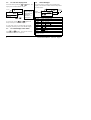
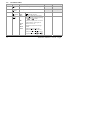
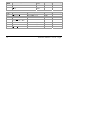
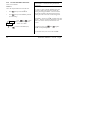
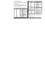
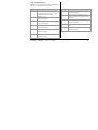
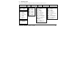
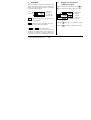
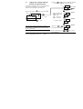
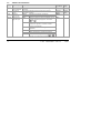
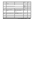
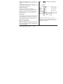
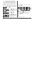
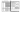
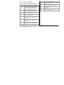
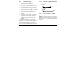
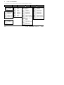
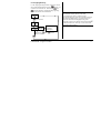
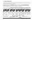
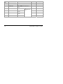
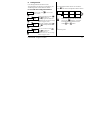
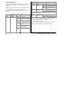
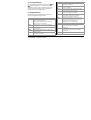
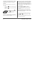
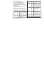
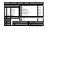
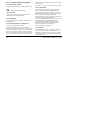
3.8 Parameter Lists
Shaded boxes are hidden when shipped from the factory.
To reveal see ‘’To Hide, Reveal and Promote Parameters” section 3.10
HC.db
Hys.C
HYS.H
Ont.C
Ont.H
OP.Hi
OP.Lo
CJC
O
SPrr
SP H
SP L
AdC
Lb t
HY
diSP
m A
w.SP
Home
List
Alarm
List
Autotune
List
PID
List
(2)
Setpoint
List
Input
List
Output
List
(2)
On/Off
List
Access List
20.0
AL
Atun
Pid
SP
iP
oP
On.Of
ACCS
1---
(1)
2---
(1)
3---
(1)
OP
tunE
Pb
ti
td
rES
Lcb
Hcb
rEL.C
OFS.H
FiLt
mV
OFS
CAL.P
CAL
Pnt.L
OFS.L
Pnt.H
CYC.H
CYC.C
codE
Goto
Conf
tmr
dwel
StAt
tm.OP
(2) Either the PID list or the On/Off list
will be present depending upon the
configuration of the controller.
X2
(1) In place of dashes, the last
three letters depend on the
alarm type.

Part Number HA026270 Issue 5.0 Aug 07 11
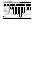
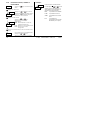
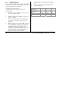
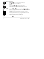
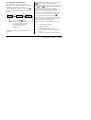
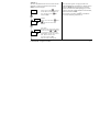
3.8.1 Summary
1. Press
to step across list headings.
2. Press
to step down parameters
3. Press
to view the value of a parameter. Keep pressing to decrease the value.
4. Press
to view the value of a parameter. Keep pressing to increase the value

12 Part Number HA026270 Issue 5.0 Aug 07
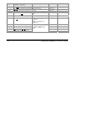
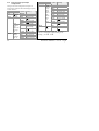
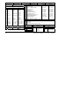
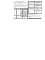
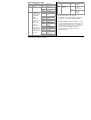
3.9 Parameter Tables
Home List
Adjustable Range Default setting Customer setting
Op
O
utput
P
ower
-100% = max cooling, 100.0% = max heating.
w.SP
W
orking
S
etpoint
Only appears when setpoint rate limit enabled
Read only Read only
m-A
M
anual/
A
uto Select
Auto
mAn
Auto
matic control selected
Man
ual standby selected
Auto
disp
Home
Disp
lay
Options
Std
OP
NonE
PV
AL.SP
pv.aL
St
andard - Shows the process value
with the setpoint accessed by pressing
the
and buttons.
Displays the output power - for use as
a manual station. (Only applies to
software version 1.4)
Blank Display (only alarm messages
flashed)
Displays the P
rocess Value only
Displays the Al
arm 2 Setpoint only
Displays the P
rocess Value with Alarm
2 Setpoint accessed by
and .
Std

Part Number HA026270 Issue 5.0 Aug 07 13
AL
Alarm List (See
section 3.7)
Adjustable
Range
Default
Setting
Customer setting
1---
Alarm 1
Setpoint
0
2---
Alarm 2
Setpoint
0
3---
Alarm 3
Setpoint
In place of dashes, the last
three letters indicate the
alarm type:
Between low
and high
setpoint limits
0
-FSL
F
ull Scale Low
-FSH
F
ull Scale High
-dEv
Dev
iation
-dHi
D
eviation High
-dLo
D
eviation Low
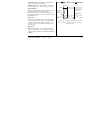
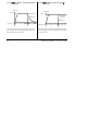
HY
Alarm Hys
teresis 1 to 9999 in display units (This value is
common to all alarms) Hysterisis is used to
prevent the alarm output ‘chattering’ by setting
a difference between the alarm switch ON and
switch OFF points
1
Lb t
L
oop Break Time OFF to 9999 minutes
OFF

14 Part Number HA026270 Issue 5.0 Aug 07
Atun
Automatic Tuning List (See section 4.3)
Adjustable
Range
Default Setting Customer setting
tunE
Automatic Tune
Enable OFF or on
Off
Adc
A
utomatic Manual reset calculation (when P+D
control)
man or
caLc
man
PiD
PID List (See section 4.3) Adjustable Range Default Setting Customer setting
Pb
P
roportional Band 1 to 999.9 display units
20
ti
I
ntegral Time OFF to 9999 seconds
360
td
D
erivative Time OFF to 9999 seconds
60
rES
Manual Res
et Value
(only present if ti= OFF)
-100 to 100.0 %
0.0
Lcb
L
ow Cutback Auto to 999.9 display units
Auto
Hcb
H
igh Cutback Auto to 999.9 display units
Auto
rEL.C
Rel
ative Cool Gain 0.01 to 10.00
1.00

Part Number HA026270 Issue 5.0 Aug 07 15
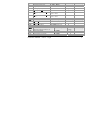
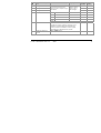
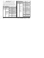
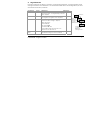
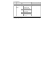
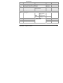
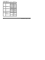
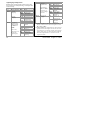
SP
Setpoint List (See also ‘To Use
the Timer’ section 3.11)
Adjustable Range Default Setting Customer setting
SP L
S
etpoint Low Limit -1999 to 999.9 As per order
SP H
S
etpoint High Limit -1999 to 999.9 As per order
sprr
S
etpoint Rate Limit 0FF to 999.9 display units
per minute
Off
tm.OP
T
imer Operating Mode Opt.1 to Opt.5
OPt.1
tmr
T
ime Remaining 0 to 9999 minutes
0
dwEl
Dwell Time 0FF to 9999 minutes
OFF
StAt
Timer Stat
us OFF or on
OFF

16 Part Number HA026270 Issue 5.0 Aug 07
iP
Input List (See also ‘User
Calibration’ section 4.2)
Adjustable Range Default Setting Customer setting
FiLt
Input Filt
er Time Constant 0FF to 999.9 seconds
1.6
CJC
*
C
old Junction Temperature measured at rear terminals Read only
mV
M
illivolt Input measured at the rear terminals Read only
OFS
Process value Of
fset -1999 to 9999 display
units
0
CAL.P
Cal
ibration Password 0 to 9999
3
CAL
User Cal
ibration Enable FACt Re-instates factory
calibration
USEr Re-instates user
calibration
FACt
Pnt.L
L
ow Calibration Point
0
OFS.L
L
ow Point Calibration Offset
0
Pnt.H
H
igh Calibration Point
100
OFS.H
H
igh Point Calibration Offset
-1999 to 9999 display
units
0

Part Number HA026270 Issue 5.0 Aug 07 17
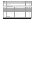
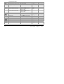
oP
Output List
Adjustable Range Default Setting Customer setting
OP.Lo
Lo
w Output Power Limit -100 to 100.0 %
0
OP.Hi
Hi
gh Output Power Limit -100 to 100.0 %
100.0
CYC.H
H
eating Output Cycle Time 0.2 to 999.9 seconds 1.0 Lgc 20 Rly
CYC.C
C
ooling Output Cycle Time 0.2 to 999.9 seconds 5.0 Lgc 20 Rly
ont.H
H
eating Output Minimum On
T
ime
Auto to 999.9 seconds
(Auto = 50ms)
Auto
ont.C
C
ooling Output Minimum On
T
ime
Auto to 999.9 seconds
(Auto = 50ms)
auto
onOF
On Off Output List
Adjustable Range Default Setting Customer setting
hYS.H
H
eating Hysteresis 1 to 9999 display units
1
hYS.C
C
ooling Hysteresis 1 to 9999 display units
1
HC.db
H
eat/Cool Deadband 0 to 9999 display units
0
ACCS
Access List (See “To Hide, Reveal and
Promote” parameters section 3.10)
Adjustable Range Default
Setting
Customer setting
codE
Access Pass Number 0 to 9999
1
Goto
Go To Required Access Level Oper, Ful, Edit, conf
OPEr
Conf
Configuration Pass Number
0 to 9999
2
Seite wird geladen ...
Seite wird geladen ...
Seite wird geladen ...
Seite wird geladen ...
Seite wird geladen ...
Seite wird geladen ...
Seite wird geladen ...
Seite wird geladen ...
Seite wird geladen ...

Part Number HA026270 Issue 5.0 Aug 07 27
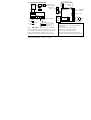
4.1.1 Instrument Configuration
inst
Instr Conf
Options
Description
*C
Centigrade
*F
Fahrenheit
*K
Kelvin
unit
Display units
nonE
None
nnnn
None
nnn.n
One
dEC.P
Decimal
places in
display
nn.nn
Two
Pid
PID Control
On.OF
On/off Control
CtrL
Control type
AL
Convert to an
alarm unit
rEv
Reverse
(normal action
for
temperature
control)
Act
Control
action
dir
Direct (output
decreases as
PV falls below
SP)
Inst
Instr Conf Options Description
HoLd
In Auto holds
manual reset
value
Pd.tr
Manual
reset
tracking (PD
control)
trAc
In Auto tracks
output for
bumpless A/M
transfer

28 Part Number HA026270 Issue 5.0 Aug 07
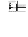
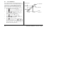
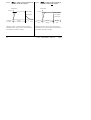
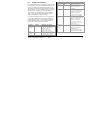
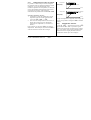
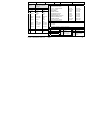
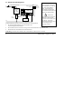
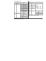
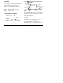
4.1.2 Input Configuration
iP
Sensor
Input
Options Meaning
j.tc
J
thermocouple
k.tc
K
thermocouple
L.tc
L
thermocouple
r.tc
R
thermocouple
b.tc
B
thermocouple
n.tc
N
thermocouple
t.tc
T
thermocouple
S.tc
S
thermocouple
PL 2
P
latinell II
rtd
100Ω PRT
mV
Linear mV
inPt
Inp
ut
t
ype
C.tc
C
ustom input
C=default
Auto
Auto
matic
0*C
0°C external ref.
45*C
45°C external ref.
CJC
(TC
only)
C
old
j
unction
c
ompen
sation
50*C
50°C external ref.
Linear input scaling (Range -12 to +80mV)
InP.L
mV inp
ut
l
ow
InP.H
mV inp
ut
h
igh
VaL.L
Displayed
val
ue low
VAL.H
Displayed
val
ue high
OFF
Off (Linear
inputs only)
Auto
1.5KΩ
Hi
5KΩ
ImP
Sensor
break
input
imp
edance
HiHi
15KΩ,
Inp.L
Inp.H
VAL.H
VAL.L
m
V
Displayed value
Seite wird geladen ...
Seite wird geladen ...
Seite wird geladen ...

32 Part Number HA026270 Issue 5.0 Aug 07
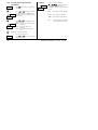
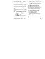
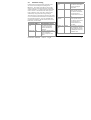
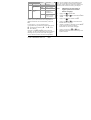
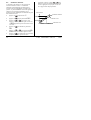
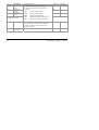
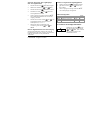
4.1.8 Passwords
PASS
Passwords Range Default
ACC.P
Full and Edit
level password
0-9999 1
CnF.P
C
onfiguration
level p
assword
0-9999 2
CAL.P
User
cal
ibration
p
assword
0-9999 3
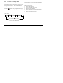
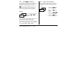
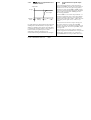
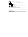
4.1.9 To leave Configuration level
Press to reach the ‘exit’ display
Press
or to select ‘YES’ After 2 secs the display
will blink and return to the HOME display in Operator level.
YES
Exit
Seite wird geladen ...
Seite wird geladen ...
Seite wird geladen ...
Seite wird geladen ...
Seite wird geladen ...
Seite wird geladen ...
Seite wird geladen ...
Seite wird geladen ...
Seite wird geladen ...
Seite wird geladen ...
Seite wird geladen ...
Seite wird geladen ...
Seite wird geladen ...

46 Part Number HA026270 Issue 5.0 Aug 07
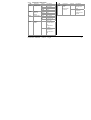
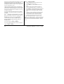
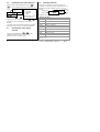
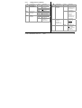
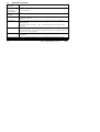
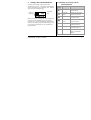
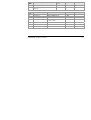
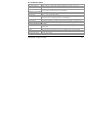
8. RoHS Certificate
Product group
2100
Table listing restricted substances
Chinese
产
2100
铅
镉
铬
溴
联
苯
溴
苯醚
线组
XOX O O O
属
OOO O O O
显
XOO O O O
块
XOX O O O
O
X
English
Product
2100
Pb H
g
Cd Cr
(
VI
)
PBB PBDE
PCBA X O X O O O
Enclosure O O O O O O
Display X O O O O O
Modules X O X O O O
O
X
Approval
Name: Position: Signature: Date:
Martin Greenhalgh Quality Manager
IA029470U450 (CN23172) Issue 1 Feb 07
Indicates that this toxic or hazardous substance contained in at least one of the homogeneous
materials used for this part is above the limit requirement in SJ/T11363-2006.
该质该质
SJ/T11363-2006
标规
Toxic and hazardous substances and elements
Indicates that this toxic or hazardous substance contained in all of the homogeneous materials for
this part is below the limit requirement in SJ/T11363-2006.
Restricted Materials Table
Restriction of Hazardous Substances (RoHS)
览
质
该质该质
SJ/T11363-2006
标规
Seite wird geladen ...

Seite wird geladen ...
Seite wird geladen ...
Seite wird geladen ...
Seite wird geladen ...
Seite wird geladen ...
Seite wird geladen ...
Seite wird geladen ...
Seite wird geladen ...
Seite wird geladen ...

10 N
0
Réf HA026270FRA Indice 5.0 08/07
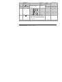
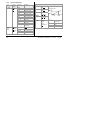
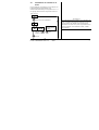
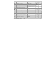
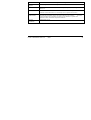
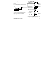
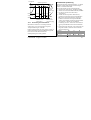
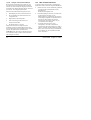
3.8 Listes de Parametres
(2) La liste PID ou la liste On/Off est
affichée, selon la configuration du
régulateur.
Les cases grisées sont normalement cachées lorsque l'appareil sort
d'usine.
Pour les faire apparaître, cf. ‘’Paramètres cachés, visibles et
personnalisés”, paragraphe 3.10
HC.db
Hys.C
HYS.H
Ont.C
Ont.H
OP.Hi
OP.Lo
CJC
O
SPrr
SP H
SP L
AdC
Lb t
HY
diSP
m A
w.SP
Page de
repos
Liste
Alarme
Liste Auto-
réglage
Liste
PID
(2)
Liste
Consigne
Liste
Entrée
Liste
Sortie
Liste
On/Off
(2)
Liste Accès
20.0
AL
Atun
Pid
SP
iP
oP
On.Of
ACCS
1---
(1)
2---
(1)
3---
(1)
OP
tunE
Pb
ti
td
rES
Lcb
Hcb
rEL.C
OFS.H
FiLt
mV
OFS
CAL.P
CAL
Pnt.L
OFS.L
Pnt.H
CYC.H
CYC.C
codE
Goto
Conf
tmr
dwel
StAt
tm.OP
X2
(1) A la place des tirets, les trois
dernières lettres dépendent du type
d'alarme. Cf. “Réglage des consignes
d'alarme paragraphe 3.7.
Seite wird geladen ...
Seite wird geladen ...
Seite wird geladen ...
Seite wird geladen ...

N
0
Réf HA026270FRA Indice 5.0 08/07 15
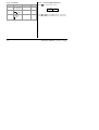
SP
Liste Consignes (cf.
paragraphe 3.11)
Plage réglable Réglage par
défaut
Réglage
client
SP L
Limite basse de la consigne -1999 à 999,9 Selon la
commande
SP H
Limite haute de la consigne -1999 à 999,.9 Selon la
commande
sprr
Limite de vitesse de la consigne 0FF à 999,9 unités affichées par
minute
Off
tm.OP
Mode de fonctionnement du
timer
Opt.1 à Opt.5
OPt.1
tmr
Temps restant 0 à 9999 minutes
0
dwEl
Temps de palier 0FF à 9999 minutes
OFF
StAt
Etat du timer OFF ou on
OFF
Seite wird geladen ...

N
0
Réf HA026270FRA Indice 5.0 08/07 17
oP
Liste Sorties Plage réglable Réglage
par défaut
Réglage
client
OP.Lo
Limite basse de puissance -100 à 100,0 %
0
OP.Hi
Limite haute de puissance -100 à 100,0 %
100.0
CYC.H
Durée du cycle de chauffage 0,2 à 999,9 secondes
CYC.C
Durée du cycle de refroidissement 0,2 à 999,9 secondes
1.0 Lgc
20 Rly
ont.H
Durée minimale de chauffage
ont.C
Durée minimale de refroidissement
Auto à 999,9 secondes (Auto =
50 msec)
Auto
onOF
Liste Sorties On Off Plage réglable Réglage
par défaut
Réglage
client
hYS.H
Hystérésis de chauffage 1 à 9999 unités affichées
1
hYS.C
Hystérésis de refroidissement 1 à 9999 unités affichées
1
HC.db
Bande morte de chauffage/refroidissement 0 à 9999 unités affichées
0
ACCS
Liste Accès (Cf. paramètres “Cachés,
Visibles et Personnalisés” paragraphe 3.10)
Plage réglable Réglage
par défaut
Réglage
client
codE
Code d'accès 0 à 9999
1
Goto
Niveau d'accès sélectionné
Oper, Ful, Edit, conf
OPEr
Conf
Code d'accès de configuration 0 à 9999
2
Seite wird geladen ...
Seite wird geladen ...
Seite wird geladen ...
Seite wird geladen ...
Seite wird geladen ...
Seite wird geladen ...
Seite wird geladen ...
Seite wird geladen ...
Seite wird geladen ...

N
0
Réf HA026270FRA Indice 5.0 08/07 27
4.1.1 Configuration de l'appareil
inst
Configuration
de l'appareil
Options Signification
*C
C
elsius
*F
F
ahrenheit
*K
K
elvin
unit
Unités affichées
nonE
Pas d'unité
nnnn
Néant
nnn.n
Une décimale
dEC.P
Résolution de
l'affichage
nn.nn
Deux décimales
Pid
PID
On.OF
Tout ou rien
CtrL
Type de
régulation
AL
Convertit le
régulateur en
unité d'alarme
inst
Configuration
de l'appareil
Options Signification
rEv
Inverse (action
normale pour la
régulation de la
température)
Act
Action de
régulation
dir
Directe (la
sortie diminue
lorsque la
valeur de
régulation passe
en-dessous de
la consigne)
Pd.tr
Suivi de
l’intégrale
manuelle
(régulation PD)
HoLd
En mode Auto,
maintient
la
valeur de
l'intégrale
manuelle
trAc
En mode Auto,
suit
la sortie
pour le transfert
progressif
Auto/Manuel
Seite wird geladen ...
Seite wird geladen ...
Seite wird geladen ...
Seite wird geladen ...
Seite wird geladen ...
Seite wird geladen ...
Seite wird geladen ...
Seite wird geladen ...
Seite wird geladen ...
Seite wird geladen ...
Seite wird geladen ...
Seite wird geladen ...
Seite wird geladen ...
Seite wird geladen ...
Seite wird geladen ...
Seite wird geladen ...
Seite wird geladen ...
Seite wird geladen ...
Seite wird geladen ...
Seite wird geladen ...
Seite wird geladen ...
Seite wird geladen ...
Seite wird geladen ...
Seite wird geladen ...
Seite wird geladen ...
Seite wird geladen ...
Seite wird geladen ...
Seite wird geladen ...
Seite wird geladen ...
Seite wird geladen ...
Seite wird geladen ...
Seite wird geladen ...
Seite wird geladen ...
Seite wird geladen ...
Seite wird geladen ...
Seite wird geladen ...
Seite wird geladen ...
Seite wird geladen ...
Seite wird geladen ...
Seite wird geladen ...
Seite wird geladen ...
Seite wird geladen ...
Seite wird geladen ...
Seite wird geladen ...
Seite wird geladen ...
Seite wird geladen ...
Seite wird geladen ...
Seite wird geladen ...
Seite wird geladen ...
Seite wird geladen ...
Seite wird geladen ...
Seite wird geladen ...
Seite wird geladen ...
Seite wird geladen ...
Seite wird geladen ...
Seite wird geladen ...
Seite wird geladen ...
Seite wird geladen ...
Seite wird geladen ...
Seite wird geladen ...
Seite wird geladen ...
Seite wird geladen ...
Seite wird geladen ...
Seite wird geladen ...
Seite wird geladen ...
Seite wird geladen ...
Seite wird geladen ...
Seite wird geladen ...
Seite wird geladen ...
Seite wird geladen ...
Seite wird geladen ...
Seite wird geladen ...
Seite wird geladen ...
Seite wird geladen ...
Seite wird geladen ...
Seite wird geladen ...
Seite wird geladen ...
Seite wird geladen ...
Seite wird geladen ...
-
 1
1
-
 2
2
-
 3
3
-
 4
4
-
 5
5
-
 6
6
-
 7
7
-
 8
8
-
 9
9
-
 10
10
-
 11
11
-
 12
12
-
 13
13
-
 14
14
-
 15
15
-
 16
16
-
 17
17
-
 18
18
-
 19
19
-
 20
20
-
 21
21
-
 22
22
-
 23
23
-
 24
24
-
 25
25
-
 26
26
-
 27
27
-
 28
28
-
 29
29
-
 30
30
-
 31
31
-
 32
32
-
 33
33
-
 34
34
-
 35
35
-
 36
36
-
 37
37
-
 38
38
-
 39
39
-
 40
40
-
 41
41
-
 42
42
-
 43
43
-
 44
44
-
 45
45
-
 46
46
-
 47
47
-
 48
48
-
 49
49
-
 50
50
-
 51
51
-
 52
52
-
 53
53
-
 54
54
-
 55
55
-
 56
56
-
 57
57
-
 58
58
-
 59
59
-
 60
60
-
 61
61
-
 62
62
-
 63
63
-
 64
64
-
 65
65
-
 66
66
-
 67
67
-
 68
68
-
 69
69
-
 70
70
-
 71
71
-
 72
72
-
 73
73
-
 74
74
-
 75
75
-
 76
76
-
 77
77
-
 78
78
-
 79
79
-
 80
80
-
 81
81
-
 82
82
-
 83
83
-
 84
84
-
 85
85
-
 86
86
-
 87
87
-
 88
88
-
 89
89
-
 90
90
-
 91
91
-
 92
92
-
 93
93
-
 94
94
-
 95
95
-
 96
96
-
 97
97
-
 98
98
-
 99
99
-
 100
100
-
 101
101
-
 102
102
-
 103
103
-
 104
104
-
 105
105
-
 106
106
-
 107
107
-
 108
108
-
 109
109
-
 110
110
-
 111
111
-
 112
112
-
 113
113
-
 114
114
-
 115
115
-
 116
116
-
 117
117
-
 118
118
-
 119
119
-
 120
120
-
 121
121
-
 122
122
-
 123
123
-
 124
124
-
 125
125
-
 126
126
-
 127
127
-
 128
128
-
 129
129
-
 130
130
-
 131
131
-
 132
132
-
 133
133
-
 134
134
-
 135
135
-
 136
136
-
 137
137
-
 138
138
-
 139
139
-
 140
140
-
 141
141
-
 142
142
-
 143
143
-
 144
144
-
 145
145
-
 146
146
-
 147
147
-
 148
148
-
 149
149
-
 150
150
-
 151
151
-
 152
152
-
 153
153
-
 154
154
-
 155
155
-
 156
156


in anderen Sprachen
- English: Eurotherm 2116/2132 Owner's manual
- français: Eurotherm 2116/2132 Le manuel du propriétaire
Verwandte Artikel
-
Eurotherm 3216L Installationsanleitung
-
-
-
-
-
Eurotherm 2108i Bedienungsanleitung
-
-
-
-
Andere Dokumente
-
Nordcap Regler ST501-LC3JAR.XXF Hot Display Case Benutzerhandbuch
-
 Evco EV3423M3 Instructions Sheet
-
Ascon tecnologic TLK38 Bedienungsanleitung
-
ABB CC-E/TC Instruction Sheet
-
ASTRO Tokai Benutzerhandbuch
-
Munters M-AirCM-B1905 Bedienungsanleitung
-
Siemens REV12 Installation Instructions Manual
-
-
Esse-ti ST56 INTL Benutzerhandbuch
-
 Delphi YDT262 Operating And Servicing Manual

