SICK IPG2 protective pipe Mounting instructions
- Typ
- Mounting instructions

DEUTSCH
Schutzrohr IPG2
für Lichtgitter MLG-2
Montageanleitung
Zusätzlich zur Montageanleitung gibt es die ausführ-
lichen Betriebsanleitungen für die Lichtgitter MLG-2.
Die Betriebsanleitungen umfassen alle Informationen
wie z.B. Montage, Elektrischen Anschluss, Einstellun-
gen und technische Daten zum Lichtgitter MLG-2.
Sie können die Betriebsanleitungen über das Internet
herunterladen:
•
www.mysick.com/de/mlg-2_pro
•
www.mysick.com/de/mlg-2_prime
Sicherheitshinweise
•
Vor der Inbetriebnahme die Anleitung lesen.
•
Anschluss, Montage, Einstellungen nur durch Fach-
personal.
•
Kein Sicherheitsbauteil gemäß EU-Maschinenricht-
linie.
•
Gerät bei Inbetriebnahme vor Feuchte und Verun-
reinigung schützen.
•
Diese Anleitung enthält Informationen, die wäh-
rend des Lebenszyklus des Geräts notwendig sind.
Hinweise
•
Schutzrohr bei Raumtemperatur montieren.
•
Je nach Länge des Schutzrohrs und der Einsatz-
temperatur das Schutzrohr mit zusätzlichen Stütz-
halterungen montieren. Siehe Abbildung „Abmes-
sung“ und Tabelle„Erforderliche Befestigung“.
Bestimmungsgemäße Verwendung
Die Lichtgitter MLG-2 erreichen in das Schutzrohr
IPG2 eingebaut, die Schutzart IP 67. Das Schutzrohr
dient dazu das Lichtgitter vor Staub und Strahlwasser
zu schützen.
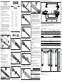
Lieferumfang und Zubehör
12
6
7
3
4
5
8
9
ß
1. Schutzrohr IPG2
2. Abstandshalter MLG-2
3. Haltewinkel oben inkl. Schrauben, optionales Zubehör
4. Zentrierung mit Gewindestift
5. Endkappe
6. Leitungsverschraubung
7. Dichteinsatz
8. Mutter
9. Haltewinkel unten, optionales Zubehör
ß Edelstahlstützhalterung, optionales Zubehör
Für optionales Zubehör siehe Tabelle „Zubehör“.
Montage und Elektrischer Anschluss
Erforderliches Werkzeug
•
Innensechskantschlüssel SW 3
•
Innensechskantschlüssel SW 8
•
Drehmomentschlüssel SW 32, 1,7 Nm
•
Drehmomentschlüssel SW 33, 4 Nm
•
Drehmomentschlüssel SW 33, 10 Nm
1. Schutzfolie vom Schutzrohr entfernen.
2. Schutzrohr reinigen. Beachten Sie die Hinweise
im Abschnitt „Reinigung“.
==
3. Alle Abstandshalter gleichmäßig auf das Lichtgit-
ter montieren.
4. Lichtgitter mit dem Abstandshalter vorsichtig in
das Schutzrohr schieben.
5. Zentrierung auf die Anschlussleitung oder An-
schlussleitungen schieben.
6. Lichtgitter mit der Zentrierung soweit in das
Schutzrohr schieben, bis das Lichtgitter im obe-
ren Flansch einrastet. Endkappe in das Schutz-
rohr einschrauben. Drehmoment: 1,7 Nm
7. Über den Gewindestift in der Zentrierung das
Lichtgitter im Schutzrohr fest positionieren.
8. Leitungsverschraubung mit Endstück verschrau-
ben. Drehmoment: 4 Nm
9. Dichteinsatz mit einem Loch oder Dichteinsatz
mit zwei Löchern montieren und in die Leitungs-
verschraubung schieben.
10. Kappe auf die Leitungsverschraubung schrauben.
Drehmoment: 10 Nm
11. Bei Schutzrohrlängen bis zu 1420 mm:
Unteren Haltewinkel am gewünschten Montageort
montieren. Lichtgitter mit dem Schutzrohr in den
unteren Halter einsetzen.
12. (Oberen) Haltewinkel am Schutzrohr montieren.
8018943/14KO/2019-07/KOD
==
13. Stützhalterungen wie folgt montieren:
— Bei Schutzrohrlängen ab 1200 mm:
Stützhalterung (Artikelnr. 2026849)
in der Mitte des Lichtgitters montieren.
— Bei Schutzrohrlängen ab 1420 mm
und einem Einsatztemperaturbereich
von –20 °C bis +55 °C:
Stützhalterungen (Artikelnr. 2088586) gleich-
mäßig über die Lichtgitterlänge montieren.
14. Empndlichkeit einlernen (Teach-in). Für eine be-
triebssichere Funktion muss die Empndlichkeit
entsprechend der vorhandenen Reichweite ein-
gelernt werden. Weitere Informationen siehe ent-
sprechende Betriebsanleitung.
Reinigung
Reinigen Sie das Schutzrohr in regelmäßigen Abstän-
den. Beachten Sie bei der Reinigung folgende Punkte:
•
Kein aggressives Reinigungsmittel verwenden.
•
Keine abriebfördernden Reinigungsmittel verwen-
den.
•
Durch statische Auadung bleiben Staubteilchen
am Schutzrohr hängen. Sie können diesen Eekt
mindern, wenn Sie zur Reinigung den antistati-
schen Kunststoreiniger (Artikelnr. 5600006) und
das SICK-Optiktuch (Artikelnr. 4003353) verwen-
den.
Gehen Sie bei der Reinigung des Schutzrohres wie
folgt vor:
1. Verschmutzungen auf dem Schutzrohr mit reich-
lich Wasser entfernen. Sie vermeiden so Kratzer
auf der Oberäche.
2. Wasserreste auf Schutzrohr entfernen. Hierzu mit
einem sauberen und leicht feuchten Tuch nach-
wischen.
3. Schutzrohr mit einem sauberen und fusselfreien
Tuch trocknen.
Wartung
SICK-Geräte sind wartungsfrei.
Wir empfehlen in regelmäßigen Abständen, das Gerät
zu reinigen und Verschraubungen und Steckverbin-
dungen zu prüfen.
Veränderungen an Geräten dürfen nicht vorgenom-
men werden. Irrtümer und Änderungen vorbehalten.
Angegebene Produkteigenschaften und technische
Daten stellen keine Garantieerklärung dar.
Entsorgung
Die Entsorgung des Geräts hat gemäß den länderspe-
zisch anwendbaren Vorschriften zu erfolgen. Für die
enthaltenen Wertstoe (insbesondere Edelmetalle) ist
im Rahmen der Entsorgung eine Verwertung anzustre-
ben.
Technische Daten Schutzrohr IPG2
Reichweite mit Schutzrohr
Das Schutzrohr verringert die Betriebsreichweite der
Lichtgitter gemäß folgender Tabelle.
Gerät Betriebsreichweite [m] Reichweite mit
Schutzrohr [m]
MLG-2 8,5 6,3
5 3,75
2 (nur MLG-2 Pro) 1,5
Beschreibung Wert
Schutzart IP 67
Material • Schutzrohr: PMMA
• Endkappen: Aluminium
• Zentrierung: Aluminium
• Abstandshalter: Kunststo
• Leitungsverschraubung: Kunststo
Umgebungs-
temperatur
–20 °C … +55 °C
IPG2
Irrtümer und Änderungen vorbehalten
BZ int47
Please find detailed addresses and additional representatives and agencies in
all major industrial nations at www.sick.com
Australia
Phone +61 3 9457 0600
Austria
Phone +43 22 36 62 28 8-0
Belgium/Luxembourg
Phone +32 2 466 55 66
Brazil
Phone +55 11 3215-4900
Canada
Phone +1 905 771 14 44
Czech Republic
Phone +420 2 57 91 18 50
Chile
Phone +56 2 2274 7430
China
Phone +86 20 2882 3600
Denmark
Phone +45 45 82 64 00
Finland
Phone +358-9-2515 800
France
Phone +33 1 64 62 35 00
Germany
Phone +49 211 5301-301
Hong Kong
Phone +852 2153 6300
Hungary
Phone +36 1 371 2680
India
Phone +91 22 6119 8900
Israel
Phone +972 4 6881000
Italy
Phone +39 02 274341
Japan
Phone +81 3 5309 2112
Malaysia
Phone +6 03 8080 7425
Mexico
Phone +52 (472) 748 9451
Netherlands
Phone +31 30 2044 000
New Zealand
Phone +64 9 415 0459
Norway
Phone +47 67 81 50 00
Poland
Phone +48 22 539 41 00
Romania
Phone +40 356 171 120
Russia
Phone +7 495 775 05 30
Singapore
Phone +65 6744 3732
Slovakia
Phone +421 482 901201
Slovenia
Phone +386 591 788 49
South Africa
Phone +27 11 472 3733
South Korea
Phone +82 2 786 6321
Spain
Phone +34 93 480 31 00
Sweden
Phone +46 10 110 10 00
Switzerland
Phone +41 41 619 29 39
Taiwan
Phone +886 2 2375-6288
Thailand
Phone +66 2645 0009
Turkey
Phone +90 216 528 50 00
United Arab Emirates
Phone +971 4 88 65 878
United Kingdom
Phone +44 1727 831121
USA
Phone +1 800 325 7425
Vietnam
Phone +84 945452999
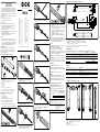
Abmessungen Schutzrohr IPG2 und Montagevarianten
30
54
14
14
5,4
L + 96
1
SW 32
37
∅ 37
SW 33
37
∅ 50
∅ 52,3
41
∅ 30
68
L
L + 107
2
3
24,1
4
Abmessungen Schutzrohr IPG2 und Montagevarianten abhängig von der Schutzrohrlänge und dem Einsatztemperatur be-
reich. Weitere Abmessungen auf Anfrage. Alle Maße in mm.
1. Montagevariante 1: Mit oberen und unteren Haltewinkl (Artikelnr. 2082211)
2. Montagevariante 2: Mit oberen und unteren Haltewinkel (Artikelnr. 2082211) und Stützhalterungen (Artikelnr. 2026849)
3. Montagevariante 3: Mit Haltewinkel und Stützhalterungen (Artikelnr. 2088586)
4. Abstand 1. Lichtstrahl von der Schutzrohrkante
Erforderliche Befestigung
Montage-
variante
Schutzrohr-Typ Schutzrohrlänge L Einsatz-
temperaturbereich
Artikelnr.
Zubehör
1
IPG2-0220 bis IPG2-0970 220 mm … 970 mm –20 °C … +55 °C 2082211
2
IPG2-1120 bis IPG2-1270 1120 mm … 1270 mm –20 °C … +55 °C 2082211 und
2026849
2
IPG2-1420 bis IPG2-2920 1420 mm … 2920 mm 0 °C … +35 °C 2082211 und
2026849
3
–20 °C … +55 °C 2088568
Zubehör
Artikelnr. Typ Beschreibung
2082211 BEF-WK-IPG2 Edelstahlhaltewinkel: Haltewinkel oben, 1 Stück und
Haltewinkel unten, 1 Stück
2026849 BEF-2AAADES2 Edelstahlstützhalterung, 2 Stück
2088586 BEF-IPG2 Long Tube Edelstahlhaltewinkel 1 Stück und Edelstahlstützhalterung, 3 Stück
Laser-Ausrichthilfe für Schutzrohr IPG2
1
2
33
1
4
4
5
1. Adapter für Laser-Ausrichthilfe AR60 (Artikelnr. 2085715), enthalten in der Laser-Ausrichthilfe AR60
2. Laser-Ausrichthilfe AR60 (Artikelnr. 1015741)
3. Schutztrohr IPG2
4. Laserstrahl
5. Adapterklemme auf Anschlag mit Endstück
2006/42/EC
NO
SAFETY

ENGLISH
8018943/14KO/2019-07/KOD
IPG2
IPG2 protective pipe
for MLG-2 light grid
Mounting instruction
There are detailed operating instructions in addition
to the mounting instructions for the MLG-2 light grids.
The operating instructions contain all of the informa-
tion relating to the MLG-2 light grid, such as informa-
tion on assembly, electrical connection, settings and
technical data.
You can download the operating instructions via the
Internet at:
•
www.mysick.com/en/mlg-2_pro
•
www.mysick.com/en/mlg-2_prime
Safety notes
•
Read the instructions before commissioning.
•
Connection, mounting and settings may only be
performed by trained specialists.
•
Not a safety component in accordance with the
EU Machinery Directive.
•
When commissioning, protect the device from mois-
ture and contamination.
•
These instructions contain information required
during the life cycle of the device.
Notes
•
Mount protective pipe at room temperature.
•
Mount with additional support brackets depending
on the length of the protective pipe and the tempe-
rature at which it will be used. See the “Dimen--
sions” gure and“Required fasteners” table.
Intended use
Installed in the IPG2 protective pipe, the MLG-2
light grids achieve an enclosure rating of IP 67. The
protective pipe is used to protect the light grid from
dust and spraying water.
Scope of delivery and accessories
12
6
7
3
4
5
8
9
ß
1. IPG2 protective pipe
2. MLG-2 spacer
3. Upper bracket including screws, optional accessory
4. Centering device with setscrew
5. End cap
6. Cable gland
7. Seal insert
8. Nut
9. Lower bracket, optional accessory
ß Stainless steel support bracket, optional accessory
See the “Accessories” table for optional accessories.
Mounting and electrical connection
Required tools:
•
Allen wrench, size 3
•
Allen wrench, size 8
•
Torque wrench target value 32, 1.7 Nm
•
Torque wrench target value 33, 4 Nm
•
Torque wrench target value 33, 10 Nm
1. Remove protective lm from the protective pipe.
2. Observe the notes in the section titled “Cleaning”.
==
3. Mount all spacers evenly on the light grid.
4. Carefully push the light grid with the spacer into
the protective pipe.
5. Push the centering device onto the connecting
cable or connecting cables.
6. Push the light grid with the centering device into
the protective pipe until the light grid clicks into
place in the upper ange. Screw the end cap into
the protective pipe. Torque: 1,7 Nm
7. Using the setscrew in the centering device, secure
the light grid in position in the protective pipe.
8. Screw the cable gland with the end piece in place.
Torque: 4 Nm
9. Mount the seal insert with a single hole or seal
insert with two holes and insert it into the cable
gland.
10. Screw the cap onto the cable gland.
Torque: 10 Nm
11. For protective pipes with lengths up to 1,420 mm:
Mount the lower bracket at the desired mounting
site. Insert the light grid with the protective pipe
into the lower bracket.
12. Mount the upper bracket to the protective pipe.
==
13. Install support brackets as follows:
— For protective pipe lengths of 1,200 mm and
greater:
Mount support bracket (part number 2026849)
in the middle of the light grid.
— For protective pipe lengths of 1,420 mm and
greater and an application temperature range
of –20 °C to +55 °C:
Mount support brackets (part number:
2088586) evenly along the length of the light
grid.
14. To ensure reliable functionality during operation,
the sensitivity has to be taught in according to the
sensing range. For additional information, see the
corresponding operating instructions.
Cleaning
Clean the protective pipe at regular intervals. Observe
the following points while cleaning:
•
Do not use any corrosive cleaning agents.
•
Do not use any abrasive cleaning agents.
•
You can reduce this eect by using an anti-static
plastic cleaner (part number 5600006) and a SICK
lens cloth (part number 4003353).
Proceed as follows when cleaning the protective pipe:
1. Remove any dirt on the protective pipe with plen-
ty of water.
2. Remove any leftover water on the protective pipe.
3. Dry the protective pipe with a clean, lint-free cloth.
Maintenance
SICK devices are maintenance-free.
We recommend cleaning the device and checking
screwed and plugged connections at regular intervals.
No modications may be made to devices.
Disposal
The device must be disposed of according to the
applicable country-specic regulations. Eorts should
be made during the disposal process to recycle the
constituent materials (particularly precious metals).
IPG2 protective pipe technical data
Sensing range with protective pipe
The protective pipe reduces the operating range of
the light grid as specied in the following table.
Device
Operating range [m]
Sensing range with
protective pipe [m]
MLG-2 8,5 6.3
5 3.75
2 (only MLG-2 Pro) 1.5
Description Value
Enclosure rating IP 67
Material • Protective pipe: PMMA
• End caps: Aluminum
• Centering device: Aluminum
• Spacer: Plastic
• Cable gland: Plastic
Ambient
temperature
–20 °C … +55 °C
IPG2 Dimensions protective pipe and mounting variants
30 (1.18)
54 (2.13)
14
(0.55)
5.4
(0.21)
14
(0.55)
1
3
L + 96
(3.78)
32 AF
∅ 37
(1.46)
33 AF
∅ 50
(1.97)
∅ 52.3
(2.06)
41 (1.61)
∅ 30 (1.18)
68 (2.68)
37
(1.46)
L
2
37
(1.46)
L + 107 (4.21)
24.1
(0.95)
4
Dimensions of IPG2 protective pipe and mounting variants dependent on the protective pipe length and application tempera-
ture range. Other dimensions on request. All dimensions in mm (inch).
1. Monting variant 1: With upper and lower bracket (part number: 2082211)
2. Monting variant 2: With upper and lower bracket (part number: 2082211) and
support brackets (part number: 2026849)
3. Monting variant 3: With bracket and support brackets (part number: 2088586)
4. Distance 1st light beam from protective pie edge
Required fasteners
Monting variant Protective pipe type Protective pipe length L Application tempera-
ture range
Part no.
Accessories
1
IPG2-0220 to IPG2-0970 220 mm to 970 mm –20 °C to +55 °C 2082211
2
IPG2-1120 to IPG2-1270 1,120 mm to 1,270 mm –20 °C to +55 °C 2082211 and
2026849
2
IPG2-1420 to IPG2-2920 1,420 mm to 2,920 mm 0 °C to +35 °C 2082211 and
2026849
3
–20 °C … +55 °C 2088568
Accessories
Part number Type Designation
2082211 BEF-WK-IPG2 Stainless steel mounting bracket: Upper bracket, 1 piece and
lower bracket, 1 piece
2026849 BEF-2AAADES2 Stainless steel support bracket, 2 pieces
2088586 BEF-IPG2 Long Tube Stainless steel mounting bracket, 1 piece and
stainless steel support bracket, 3 pieces
Laser alignment aid for IPG2 protective pipe
1
2
33
1
4
4
5
1. Adapter for laser alignment aid AR60 (part number 2085715), contained in the AR60 laser alignment aid
2. Laser alignment aid AR60 (part number 1015741)
3. IPG2 protective pipe
4. Laser beam
5. Adapter clamp on stop with end cap
Please find detailed addresses and additional representatives and agencies in
all major industrial nations at www.sick.com
Subject to change without notice
BZ int47
Australia
Phone +61 3 9457 0600
Austria
Phone +43 22 36 62 28 8-0
Belgium/Luxembourg
Phone +32 2 466 55 66
Brazil
Phone +55 11 3215-4900
Canada
Phone +1 905 771 14 44
Czech Republic
Phone +420 2 57 91 18 50
Chile
Phone +56 2 2274 7430
China
Phone +86 20 2882 3600
Denmark
Phone +45 45 82 64 00
Finland
Phone +358-9-2515 800
France
Phone +33 1 64 62 35 00
Germany
Phone +49 211 5301-301
Hong Kong
Phone +852 2153 6300
Hungary
Phone +36 1 371 2680
India
Phone +91 22 6119 8900
Israel
Phone +972 4 6881000
Italy
Phone +39 02 274341
Japan
Phone +81 3 5309 2112
Malaysia
Phone +6 03 8080 7425
Mexico
Phone +52 (472) 748 9451
Netherlands
Phone +31 30 2044 000
New Zealand
Phone +64 9 415 0459
Norway
Phone +47 67 81 50 00
Poland
Phone +48 22 539 41 00
Romania
Phone +40 356 171 120
Russia
Phone +7 495 775 05 30
Singapore
Phone +65 6744 3732
Slovakia
Phone +421 482 901201
Slovenia
Phone +386 591 788 49
South Africa
Phone +27 11 472 3733
South Korea
Phone +82 2 786 6321
Spain
Phone +34 93 480 31 00
Sweden
Phone +46 10 110 10 00
Switzerland
Phone +41 41 619 29 39
Taiwan
Phone +886 2 2375-6288
Thailand
Phone +66 2645 0009
Turkey
Phone +90 216 528 50 00
United Arab Emirates
Phone +971 4 88 65 878
United Kingdom
Phone +44 1727 831121
USA
Phone +1 800 325 7425
Vietnam
Phone +84 945452999
2006/42/EC
NO
SAFETY
-
 1
1
-
 2
2


SICK IPG2 protective pipe Mounting instructions
- Typ
- Mounting instructions
in anderen Sprachen
- English: SICK IPG2 protective pipe
Verwandte Artikel
-
SICK MLG-2 IPG69K, Protective housing mounting Mounting instructions
-
-
-
-
-
-
-
-
-