
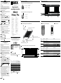
E Status LEDs
E1 Light grid front
/ Vorderseite des Lichtgitters E2 Backside / Rückseite
B Mounting and alignment / Montage und Ausrichtung
B1 Alignment of MLGR and MLGT / Ausrichtung MLGR und MLGT
B2 Position of the web relatively to the MLG-2 / Die Position der Bahn relativ zum MLG-2
A Pin assignments / Anschlussbelegung
Pin assignment receiver MLGR / Anschlussbelegung Empfänger MLGR
Pin assignment transmitter MLGT / Anschlussbelegung Sender MLGT
Supplement to
operating instruction
MLG-2
Prime / Pro
------------------------------------------------------------------- 8018898 Z840 1016 -----------------------------------------------------------------
4
3
8
21
7
6
5
3
2
1
4
5
1 brn L+
2 wht SyncA
3 blu M
4 blk Q1
1 brn L+
2 wht SyncA
3 blu M
4 blk TestIn
5 gra SyncB
5 gra SyncB
6 pnk IN1
7 vio Q
A1
8 ora Q
A2
4
3
8
21
7
6
5
3
2
1
4
5
1 brn L+
2 wht SyncA
3 blu M
4 blk Q1
1 brn L+
2 wht SyncA
3 blu M
4 blk TestIn
5 gra SyncB
5 gra SyncB
6 pnk IN1
7 vio Q
A1
8 ora Q
A2
YZ
X
Mounting distance / Befestigungsabstand
200 mm ... 300 mm
Maximum twist in Z-axis ±2° /
Maximale Verdrehung in Z-Achse ±2°
Maximum twist in X-axis ±2°/
Maximale Verdrehung in der X-Achse ±2°
Maximum twist in Y
-axis ±2°/
Maximale
Verdrehung in Y-Achse ±2°
red
yelgrn
20 mA QA1 4 mA
1 2 ......... ....... n-1 n
MLGT
MLGR
D Measurement Information / Messdaten
ENGLISH
Measuring automation light grids
Operating instructions
Valid for MLG-2 1076315, 1078725, 1082916 and 1085035 for edge
detection
Technical data
This is an operating instruction supplement to the standard operating
instruction MLG-2 Prime/Pro (8016959). Please read the enclosed
operating instruction and this operating instruction supplement carefully.
Furthermore refer to datasheet of MLG-2 available on www.sick.com.
All device properties and features which are distinguished from standard
MLG-2 devices are listed and described below.
A Key properties of MLG-2
1) This MGL-2 measures how far the web edge extends into the measure-
ment range of the light grid and outputs this result on a 4 mA – 20 mA
analog output Q
A1
2) There is no SOPAS functionality available.
B Mounting and alignment
• Transmitter MLGT and Receiver MLGR have to be mounted within a
distance of 200 mm – 300 mm apart. (see B1 )
• MLGR and MLGT have to be aligned very accurately. Consider the maxi-
mum twist angles in the diagram B1 as well a maximum displace-
ment of MLGR relatively to MLGT of 2 mm in Z-direction and 3 mm in
Y-direction.
• The position of the web relatively to the MLG-2 has to be exactly 1/3 of
the mounting distance d between transmitter and receiver. Deviations
will lead to considerable lower measurement accuracy. Note that the
web always has to be closer to MLGR.
Refer to the diagram B2 .
• As soon as your devices are mounted and aligned properly, it is
essential to execute a signal teach procedure.
C Signal teach
A signal teach calibrates the signal of every single beam according to
the current situation which is necessary to guarantee high measurement
accuracy.
The following steps have to be mAde to execute a signal teach:
1) Make sure that no web is between transmitter and receiver
(no beam blocked)
2) Set teach-input IN1 to HIGH (V
CC
) or press the teach-in button on the
backside of the receiver.
3) Yellow LED blinks permanently with a frequency of 0.5 Hz.
4) If the teach-in was not successful, the red LED will blink with a frequency
of 3 Hz (see E1 ). As a result, Q
A1
will be set to 4 mA. In this case please
check the following possible causes and try another teach-in:
a) Insucient alignment-accuracy of MLGT and MLGR.
b) Mounting distance between MLGT and MLGR exceeds 500 mm.
D Measurement Information
For measurement information see D .
E Status LEDs
LEDs on the light grid front (see E1 ).
Display on the backside of the receiver:
The display on the backside of the receiver must not be used or considered
in this sample device (see E2 ).
DEUTSCH
Messende Automatisierungs-Lichtgitter
Betriebsanleitung
Gültig für MLG-2 1076315, 1078725, 1082916 und 1085035 zur
Bahnkantenregelung
Technische Daten
Bei dem vorliegenden Dokument handelt es sich um eine ergänzende
Betriebs anleitung zur Standard-Betriebsanleitung für MLG-2 Prime/Pro
(8016959). Bitte lesen Sie sowohl die beigefügte Betriebsanleitung als
auch diese er gänzende Betriebsanleitung sorgfältig durch. Beachten Sie
darüber hinaus bitte auch das MLG-2-Datenblatt, das unter www.sick.com
abrufbar ist.
Nachfolgend werden alle Geräteeigenschaften und -funktionen aufgeführt
und beschrieben, durch die sich das vorliegende Produkt von Standard-
MLG-2-Geräten unterscheidet.
A Wichtigste Eigenschaften des vorliegenden MLG-2
1) Dieses MGL-2 misst, wie weit die Bahnkante in den Messbereich des
Lichtgitters hineinragt und gibt das Ergebnis über einen 4 mA–20 mA
Analogausgang (Q
A1
) aus.
2) Kongurationstool SOPAS nicht verfügbar.
B Montage und Ausrichtung
• Sender MLGT und Empfänger MLGR müssen innerhalb eines Abstands
von 200 mm bis 300 mm montiert werden. (Vgl. B1 )
• MLGR und MLGT müssen sehr genau ausgerichtet werden. Berücksich-
tigen Sie die in der Übersicht B1 genannten maximalen Verdrehwinkel
sowie eine maximalverschiebung des MLGR relativ zum MLGT von 2 mm
in Z-Richtung und 3 mm in Y-Richtung.
• Die Position der Bahn relativ zum MLG-2 muss genau bei 1/3 des
Montageabstands d zwischen dem Sender und dem Empfänger liegen.
Jeder Versatz führt zu einer erheblichen Beeinträchtigung der Mess-
genauigkeit. Bitte beachten Sie, dass die Bahn sich immer näher am
MLGR benden muss. (Vgl. Diagramm B2 )
• Sobald die Geräte montiert und korrekt ausgerichtet sind, muss ein
Teach-in durchgeführt werden.
C Teach-in
Im Rahmen des Teach-in wird das Signal jedes einzelnen Strahls unter
Berücksichtigung der aktuellen Gegebenheiten kalibriert. Dies ist erford-
erlich, um eine hohe Messgenauigkeit zu gewährleisten. Zur Durchführung
eines Teach-in sind folgende Schritte erforderlich:
1) Sorgen Sie dafür, dass sich zwischen Sender und Empfänger keine Bahn
bendet (dass kein Strahl blockiert wird).
2) Stellen Sie den Teach-Eingang IN1 auf HIGH (V
CC
) oder drücken Sie die
Teach-in-Taste an der Rückseite des Empfängers.
3) Die gelbe LED blinkt kontinuierlich mit einer Frequenz von 0,5 Hz.
4) Wenn der Teach-in nicht erfolgreich abgeschlossen werden konnte,
blinkt die rote LED mit einer Frequenz von 3 Hz (vgl. C1 ).
In der Folge wird der Analogausgang Q
A1
auf 4 mA eingestellt. Prüfen
Sie in diesem Fall bitte folgende mögliche Ursachen und führen Sie
anschließend den Teach-in erneut durch:
a) MLGT und MLGR sind nicht ausreichend genau ausgerichtet.
b) Der Montageabstand zwischen MLGT und MLGR beträgt mehr als
500 mm.
D Messdaten
Für Messdaten vgl. D .
LED LED state Device state What to do
Green LED Active Power -
Yellow LED Blinking @ 0.5 Hz Teach-in is active -
Blinking @ 1 Hz Signal reduction detected. The device is probably contaminated
or the light grid adjustment has changed since the last teach.
Clean device and check the adjustment. Execute teach-in
afterwards.
Red LED Blinking @ 3 Hz Teach-in was not successful.
Please check the light grid adjustment and execute another
teach-in as described in the chapter
C .
Active General failure Please contact SICK AG.
SICK AG, Erwin-Sick-Strasse 1, D-79183 Waldkirch
More representatives and agencies at www.sick.com ∙ Subject to change
without notice ∙ The specied product features and technical data do not
represent any guarantee.
Weitere Niederlassungen nden Sie unter www.sick.com ∙ Irrtümer
und Änderungen vorbehalten ∙ Angegebene Produkteigenschaften und
technische Daten stellen keine Garantieerklärung dar.
NFPA79 applications only.
Adapters providing field
wiring leads are available.
Refer to the product information.
Enclosure Type 1
33 % x d
67 % x d
d
MLGT
MLGR
LED LED-Zustand Gerätezustand Was ist zu tun?
Grüne LED Aktiv Eingeschaltet -
Gelbe LED Blinkt mit 0,5 Hz Teach-in läuft -
Blinkt mit 1 Hz Signalabschwächung erkannt. Das Gerät ist wahrscheinlich
verschmutzt oder die Lichtgitterjustierung hat sich seit dem
letzten Teach-in verändert.
Gerät säubern und Justierung prüfen. Anschließend Teach-in
erneut durchführen.
Rote LED Blinkt mit 3 Hz Teach-in ist fehlgeschlagen.
Bitte prüfen Sie die Lichtgitterjustierung und führen Sie den
Teach-in erneut durch wie im Kapitel
C beschrieben.
Aktiv Allgemeine Störung Bitte wenden Sie sich an die SICK AG.
E Status LEDs
LEDs vorne am Lichtgitter (siehe E1 ).
Display an der Empfängerrückseite:
Das Display an der Rückseite des Empfängers darf bei diesem Mustergerät
nicht verwendet /nicht berücksichtigt werden (siehe E2 ).
BZ int46
Please find detailed addresses and further locations in all major industrial
nations at www.sick.com
Australia
Phone +61 3 9457 0600
Austria
Phone +43 22 36 62 28 8-0
Belgium/Luxembourg
Phone +32 2 466 55 66
Brazil
Phone +55 11 3215-4900
Canada
Phone +1 905 771 14 44
Czech Republic
Phone +420 2 57 91 18 50
Chile
Phone +56 2 2274 7430
China
Phone +86 20 2882 3600
Denmark
Phone +45 45 82 64 00
Finland
Phone +358-9-2515 800
France
Phone +33 1 64 62 35 00
Germany
Phone +49 211 5301-301
Hong Kong
Phone +852 2153 6300
Hungary
Phone +36 1 371 2680
India
Phone +91 22 4033 8333
Israel
Phone +972 4 6881000
Italy
Phone +39 02 274341
Japan
Phone +81 3 5309 2112
Malaysia
Phone +6 03 8080 7425
Mexico
Phone +52 472 748 9451
Netherlands
Phone +31 30 2044 000
New Zealand
Phone +64 9 415 0459
Norway
Phone +47 67 81 50 00
Poland
Phone +48 22 539 41 00
Romania
Phone +40 356 171 120
Russia
Phone +7 495 775 05 30
Singapore
Phone +65 6744 3732
Slovakia
Phone +421 482 901201
Slovenia
Phone +386 591 788 49
South Africa
Phone +27 11 472 3733
South Korea
Phone +82 2 786 6321
Spain
Phone +34 93 480 31 00
Sweden
Phone +46 10 110 10 00
Switzerland
Phone +41 41 619 29 39
Taiwan
Phone +886 2 2375-6288
Thailand
Phone +66 2645 0009
Turkey
Phone +90 216 528 50 00
United Arab Emirates
Phone +971 4 88 65 878
United Kingdom
Phone +44 1727 831121
USA
Phone +1 800 325 7425
Vietnam
Phone +84 945452999
MLG-2
20 mA 4 mA
Responsetime Accuracy of
messurement
**
Reaktionszeit Messgenauigkeit
**
MLG05A-0145 ... 148 mm 0 mm 6 ms < 2 mm
MLG05A-0295
... 298 mm 0 mm 12 ms < 2 mm
MLG05A-0445
... 448 mm 0 mm 18 ms < 2 mm
MLG05A-0595
... 598 mm 0 mm 23 ms < 2 mm
MLG05A-0745
... 748 mm 0 mm 29 ms < 2 mm
MLG05A-0895
... 898 mm 0 mm 35 ms < 2 mm
MLG05A-1045
... 1048 mm 0 mm 41 ms < 2 mm
** To guarantee the specied accuracy, make sure the light grid is aligned
properly (refer to chapter B “Mounting and alignment”). /
** Zur Gewährleistung der spezizierten Genauigkeit sicherstellen, dass
das Lichtgitter korrekt ausgerichtet ist (siehe Kapitel B „Montage und
Ausrichtung“).
-
 1
1

in anderen Sprachen
Verwandte Artikel
-
SICK MLG-2 Prime/Pro Measuring automation light grids Bedienungsanleitung
-
-
-
-
-
-
-
-
-