
Protection class Schutzklasse Classe de protection Classe de proteção Classe di protezione III (EN 61 140)
Enclosure rating Schutzart Indice de protection Tipo de proteção Tipo di protezione IP 65 and IP 67 (EN 60 529)
1)
Ambient operating temperature Betriebsumgebungstemperatur Température de service Temperatura ambiente de funcionamento Temperatura ambientale di funzionamento -30 ... +55 °C
Supply voltage V
S
Versorgungsspannung U
V
Tension d'alimentation U
V
Tensão de alimentação U
V
Tensione di alimentazione U
V
24 VDC ± 20 %
2) 3)
Switching output Schaltausgang Sortie de commutation Saída de conexão Uscita di commutazione Push/Pull
2)
Digital output, output current Digitalausgang Ausgangsstrom Sortie numérique courant de sortie Saída digital corrente de saída Uscita digitale per la corrente di uscita 100 mA
2)
Typical current consumption of sender Stromaufnahme Sender typisch Consommation électrique type de l‘émetteur Consumo típico de corrente do emissor Consumo di corrente emettitore tipico 40 mA + (0.1 mA × number of beams / number of beams) / 40 mA + (0,1 mA × Strahlanzahl / Strahlanzahl)
Maximum current consumption of sender Stromaufnahme Sender maximal Consommation électrique maximale de l‘émetteur Consumo máximo de corrente do emissor Consumo di corrente emettitore massimo <55 mA + (0.1 mA × number of beams / number of beams) / <55 mA + (0,1 mA × Strahlanzahl / Strahlanzahl)
Current consumption of sender with triple simultaneous scan Stromaufnahme Sender bei 3-fach Simultanscan Consommation électrique de l‘émetteur avec triple balayage simultané Emissor do consumo de corrente com digitalização simultânea tripla Consumo di corrente emettitore con triplice
scansione simultanea
<100 mA + (0.1 mA × number of beams / number of beams) / <100 mA + (0,1 mA × Strahlanzahl / Strahlanzahl)
Typical current consumption of receiver Stromaufnahme Empfänger typisch Consommation électrique type du récepteur Consumo típico de corrente do receptor Consumo di corrente ricevitore tipico 60 mA + (0.25 mA × number of beams / number of beams) / 60 mA + (0,25 mA × Strahlanzahl / Strahlanzahl)
Maximum current consumption of receiver Stromaufnahme Empfänger maximal Consommation électrique maximale du récepteur Consumo máximo de corrente do receptor Consumo di corrente ricevitore massimo <80 mA + (0.25 mA × number of beams / number of beams) / <80 mA + (0,25 mA × Strahlanzahl / Strahlanzahl)
Current consumption of receiver in sunlight-
resistant mode where a beam of 150 klx is sent to all receiver optics
Stromaufnahme Empfänger im sonnenlichtresistenten Modus bei Bestrahlung
aller Empfangsoptiken mit 150 klx
Consommation électrique du récepteur en
mode résistant à la lumière solaire avec rayonnement de toutes les optiques de
réception avec 150 klx
Consumo de corrente do receptor no modo
resistente à luz solar com irradiação de todos os elementos ópticos de recepção
com 150 klx
Consumo di corrente ricevitore in modalità
resistente ai raggi solari con irraggiamento di tutti i sensori ottici di ricezione con
150 klx
<80 mA + (0.55 mA × number of beams / number of beams) / <80 mA + (0,55 mA × Strahlanzahl / Strahlanzahl)
Maximum current consumption of receiver – inrush current Stromaufnahme Empfänger Einschaltstrom Consommation électrique du récepteur courant de démarrage Consumo de corrente do receptor Corrente
de conexão
Consumo di corrente ricevitore corrente di attivazione 5 × current consumption / current consumption / 5 × Stromaufnahme / Stromaufnahme
Typical current consumption of fieldbus module Stromaufnahme Feldbusmodul typisch Consommation électrique type du récepteur Consumo típico de corrente do módulo de barramento de campo Consumo di corrente modulo bus di campo tipico 115 mA
Maximum current consumption of fieldbus module Stromaufnahme Feldbusmodul maximal Consommation électrique maximale du récepteur Consumo máximo de corrente do módulo de barramento de campo Consumo di corrente modulo bus di campo massimo <160 mA
1)
Do not use light grid outdoors unless protected (condensation will form)
2)
With 24 V DC and 25 °C ambient temperature
3)
Class 2
1)
Lichtgitter nicht ungeschützt im Außenbereich einsetzen (Kondenswasserbildung)
2)
Bei 24 VDC und 25° C Umgebungstemperatur
3)
Class 2
1)
Ne pas mettre en œuvre le rideau de détection sans protection en extérieur (formation
de condensation d‘eau)
2)
Avec 24 V CC et une température ambiante de 25 °C
3)
Classe 2
1)
Não utilizar a grade de luz sem proteção em exteriores (formação de condensado)
2)
Com 24 VDC e temperatura ambiente de 25°
3)
Classe 2
1)
Non utilizzare all‘esterno la barriera ottica senza protezione (formazione di condensa)
2)
Con 24 VDC e temperatura ambiente 25 °C
3)
Class 2
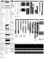
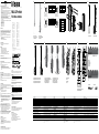
MLG-2 ProNet
Fieldbus module
NFPA79 applications only.
Adapters providing field
wiring leads are available.
Refer to the product information.
Female connector / Dose
43
2 1
CONFIG pin assignment /
Pinbelegung CONFIG
Pin Signal Meaning / Bedeutung
1 TX+ Ethernet
2 RX+ Ethernet
3 TX– Ethernet
4 RX– Ethernet
Female connector / Dose
43
2 1
BUS OUT pin assignment /
Pinbelegung BUS OUT
Pin Signal Meaning / Bedeutung
1 TX+ Ethernet
2 RX+ Ethernet
3 TX– Ethernet
4 RX– Ethernet
Female connector / Dose
43
2 1
BUS IN pin assignment /
Pinbelegung BUS IN
Pin Signal Meaning / Bedeutung
1 TX+ Ethernet
2 RX+ Ethernet
3 TX– Ethernet
4 RX– Ethernet
Male connector / Stecker
12
5
34
POWER pin assignment /
Pinbelegung POWER
Pin Signal Meaning / Bedeutung
Color /
Farbe
1
L+ 24 V supply voltage /
Versorgungsspannung
Brown /
Braun
2
Sync_A Synchronization /
Synchronisation
White /
Weiß
3
M GND supply voltage /
GND-Versorgungsspannung
Blue /
Blau
4
Q1 Switching output /
Schaltausgang
Black /
Schwarz
5
Sync_B Synchronization /
Synchronisation
Gray /
Grau
38.5
(1.52)
36.3
(1.43)
17.7
(0.70)
19.7
(0.78)
3
(0.12)
24
(0.94)
24
(0.94)
24
(0.94)
23.2
(0.91)
15.6
(0.61)
133
(5.24)
17
(0.67)
23.3
(0.92)
34
(1.34)
40.6
(1.60)
38.5
(1.52)
36.3
(1.43)
30.6
(1.20)
38.1
(1.50)
1 MLG-2 Pro sender
2 MLG-2 ProNet receiver
3 Fieldbus module
1 MLG-2 Pro Sender
2 MLG-2 ProNet Empfänger
3 Feldbusmodul
1 POWER
2 LINK/ACT
3 BF/ERR/NS
4 SF/RUN/MS
5 LINK/ACT
6 LINK/ACT
1 Mounting bracket
2 M4 x 16
1 Haltewinkel
2 M4 x 16
1 QuickFix bracket 1 QuickFix-Halterungen
1 Mounting with the connections to the front side
2 Mounting with the connections to the rear side
1 Montage mit den Anschlüssen zur Vorderseite
2 Montage mit den Anschlüssen zur Rückseite
1 Unscrew the Torx T20 mounting screw
2 Pull the eld module downwards and away
3 Turn the eld module by 180°
4 Insert the eld module again
5 Tighten the mounting screw
1 Montageschraube Torx T20 lösen
2 Feldmodul nach unten wegziehen
3 Feldmodul um 180° drehen
4 Feldmodul wieder einstecken
5 Montageschraube festdrehen
1 DIP-Schalter 1 DIP switches
1 Fieldbus module xing screw
2 Openings for mounting pins
1 Befestigungsschraube Feldbusmodul
2 Önungen für Montagestifte
Deutsch
Feldbus-Module
Quickstart
Sicherheitshinweise Feldbus-Module
• Vor der Inbetriebnahme die Betriebsanleitung lesen.
• Anschluss, Montage und Einstellung nur durch Fachpersonal.
• Kein Sicherheitsbauteil gemäß EU-Maschinenrichtlinie.
• Gerät bei Inbetriebnahme vor Feuchte und Verunreinigung schützen.
• UL: Nur zur Verwendung in Anwendungen gemäß NFPA 79. Diese Geräte
müssen mit einer für 24V DC geeigneten 1A-Sicherung abgesichert
werden. Von UL gelistete Adapter mit Anschlusskabeln sind verfügbar.
• Feldbusmodul: IP-Schutzart nicht bewertet nach UL Nutzung in max. Höhe
2000 m, max. relative Luftfeuchtigkeit 80%, Verschmutzungsgrad 2.
• Diese Betriebsanleitung enthält Informationen, die während des Lebens-
zyklus des Sensors notwendig sind.
• Die Betriebsanleitung des Feldbus-Moduls muss stets verfügbar sein und
beachtet werden.
• EtherCAT = 8018739
• EtherNet/IP = 8018741
• PROFINET = 8018745
• PROFIBUS = 8018747
• CANopen = 8018743
Bestimmungsgemäße Verwendung
Das Feldbus-Modul ist ausschließlich für die Verwendung mit dem MLG-2
ProNet vorgesehen.
Bei jeder anderen Verwendung sowie bei Änderungen am Feldbus-Modul
(z.B.durchÖnendesGehäuses,auchimRahmenvonMontageund
Elektroinstallation) oder bei Änderungen an der SICK-Software erlischt ein
Gewährleistungsanspruch gegenüber der SICK AG.
Das Feldbus-Modul ist unter anderem für nachfolgende Verwendungen nicht
geeignet:
• Als Sicherheitsvorrichtung, um Personen, deren Hände oder andere
Körperteile zu schützen
• Unter Wasser
• In explosionsgefährdeten Bereichen
• Im Außenbereich ohne zusätzlichen Schutz
Funktion und Einsatz
Das Feldbus-Modul besteht aus folgenden Komponenten:
• Feldbusmodul
Montage
• MontierenSiedasKunststoelementandasMLG-2.
• Schrauben sie zwei Stifte an das Feldbus-Modul.
• Schieben Sie das Feldbus-Modul in das MLG-2 hinein.
• Das Feldbus-Modul kann auch um 180° gedreht montiert werden.
• Ziehen Sie die Innensechskantchraube mit 0,5 Nm an.
Sie können das Feldbus-Modul außerdem abgesetzt montieren (siehe Abb.
G)
Abgesetzte Montage:
Für abgesetzte Montage kann ein Quick Fix halter verwendet werden. Das
Verbindungskabel bei abgesetzter Montage darf nicht länger wie 2,7m
haben.
Elektrische Installation
Alle Leitungen für das MLG-2 werden am Feldmodul angeschlossen (siehe
Abb. B).
Die Anschlüsse haben folgende Verwendung (siehe Abb. H):
• DEVICE: Anschluss des Empfängers
• CONFIG:AnschlusseinesNotebooks/PCszuKonguration
• BUS IN, BUS OUT: Ethernet-Anschlüsse für den Feldbus
• POWER: Anschluss der Spannungsversorgung, der Synchonisation des
Senders, Schaltausgang
Anzeigeelemente
Der Empfänger verfügt auf der Vorderseite über drei LEDs und auf der
Rückseite über ein Bedienfeld mit LEDs und Folientasten. Die LEDs und das
BedienfeldbendensichanderAnschlussseite.
Das Teach-in des MLG-2 kann mit der Taste Teach gestartet werden.
DerSenderverfügtaufderVorderseiteüberdreiLEDs.DieLEDsbenden
sich an der Anschlussseite.
Das Feldbusmodul verfügt über sechs LEDs (siehe Abb. I).
Inbetriebnahme
Nach der Montage und der elektrischen Installation müssen der Sender
und der Empfänger aufeinander ausgerichtet werden. Zwischen Sender und
EmpfängerdarfsichkeinObjektbenden.DerLichtwegmussfreisein.
Die gelbe LED an der Vorderseite des Empfängers und die LED Alignment
zeigen die grobe Ausrichtung an.
3 Hz Gelb
Die gelbe LED an der Vorderseite blinkt schnell.
• Richten Sie das MLG-2 genauer aus.
Wenn die gelbe LED und die LED Alignment erlöschen, dann ist das MLG-2
optimal ausgerichtet.
Beim MLG-2 ProNet werden Sie von SOPAS ET beim Ausrichten und Teach-in
der Empndlichkeit unterstützt (siehe Betriebsanleitung auf www.sick.
com).
• Fixieren Sie anschließend die Position des Senders und des Empfängers.
• Drücken Sie die Taste Teach (<1 s). Teach-in kann auch über SOPAS ET,
den integrierten Webserver oder die SPS ausgelöst werden.
1 Hz Gelb
Die gelbe LED an der Vorderseite und die LED Alignment blinken
langsam.
Wenn der Teach-in-Prozess erfolgreich war, dann erlöschen die gelbe LED an
der Vorderseite und die LED Alignment. Das MLG-2 ist betriebsbereit.
Schlägt der Teach-in-Prozess fehl, blinken die LEDs Alignment und RS-485/
IO-Link sowie die rote LED an der Gerätevorderseite schnell.
• Prüfen Sie, ob das MLG-2 korrekt ausgerichtet ist, ob die Frontscheiben
saubersindundobsichkeineObjekteimLichtwegbenden.
• Führen Sie dann den Teach-in-Prozess erneut durch.
Das MLG-2 wird in den jeweiligen Feldbus eingebunden. Es unterstützt
Prozessdaten zur zyklischen Kommunikation und Servicedaten zur azyk-
lischen Kommunikation. Für das MLG-2 stehen je nach Feldbussystem Gerä-
tebeschreibungsdateien und Funktionsblöcke zur Verfügung (siehe
www.sick.com).
English
Fieldbus module
Quick start
Safety notes for Fieldbus module
• Read the operating instructions before commissioning.
• Connection, mounting, and setting may only be performed by trained
specialists.
• Not a safety component in accordance with the EU Machinery Directive.
• When commissioning, protect the device from moisture and
contamination.
• UL: Only for use in applications in accordance with NFPA 79. These devic-
es must be fused with a 1 A fuse that is suitable for 30 V DC. UL-listed
adapters with connecting cables are available.
• Fieldbusmodule: IP Rating not evaluated by UL use at max. altitude
2000m, max. rel. humidity 80%, pollution degree 2
• MLG-2: Enclosure Type 1, IP Rating not evaluated by UL
• These operating instructions contain information required during the life
cycle of the sensor.
• The operating instructions for the MLG-2 ProNet must always be available
and must be followed.
• EtherCAT = 8018740
• EtherNet/IP = 8018742
• PROFINET = 8018746
• PROFIBUS = 8018748
• CANopen = 8018744
Intended use
TheeldbusmoduleisintendedexclusivelyforusewiththeMLG-2PRONET.
IntheeventofanyotherusageormodicationtotheMLG-2(e.g.dueto
opening the housing during mounting and electrical installation) or in the
event of changes made to the SICK software, any claims against SICK AG
under the warranty will be rendered void.
The Fieldbus module is not suitable for the following applications, among
others:
• As a safety device to protect persons, their hands, or other body parts
• Under water
• In explosive environments
• Outdoors, without additional protection
Function and use
The Fieldbus module comprises the following components:
• Fieldbus module
Mounting
• Mount the plastic element to the MLG-2.
• Screwtwopinstotheeldbusmodule.
• SlidetheeldbusmoduleintotheMLG-2.
• Theeldbusmodulecanalsobemountedrotatedby180°.
• Tighten the hexagon socket screw to 0.5 Nm.
Youcanalsomounttheeldbusmoduleremotely(seeFig.G)
Remote mounting:
Aquickxholdercanbeusedforremotemounting.Theconnectioncablefor
remote mounting must not be longer than 2.7m.
Electrical installation
AllcablesfortheFieldbusmoduleareconnectedtotheeldmodule(see
g.B).
Theconnectionsareusedasfollows(seeg.H):
• DEVICE: Receiver connection
• CONFIG:Notebook/PCconnectionforconguration
• BUSIN,BUSOUT:Ethernetconnectionsfortheeldbus
• POWER: Power supply connection, sender synchronization, switching
output
Status indicators
The receiver has three LEDs on its front and a control panel with LEDs and
membrane keys on its rear. The LEDs and the control panel are located on
the connection side.
The teach-in process for the MLG-2 can be started by pressing the Teach
pushbutton.
The sender has three LEDs on its front. The LEDs are located on the connec-
tion side.
TheeldbusmodulehassixLEDs(seeg.I).
Commissioning
After mounting and electrical installation, the sender and receiver must be
aligned with each other. No objects should be located between the sender
and the receiver. The light path must be clear.
The yellow LED on the front of the receiver and the Alignment LED show the
rough alignment.
3 Hz yellow
TheyellowLEDonthefrontashesrapidly.
• Improve the alignment of the MLG-2.
When the yellow LED and the Alignment LED go out, the MLG-2 is optimally
aligned.
With the MLG-2 ProNet, SOPAS ET will help you to align the device and
teach in the sensitivity (see operating instructions on www.sick.com).
• Nowxthepositionofthesenderandreceiver.
• Press the Teach pushbutton (< 1 s). The teach-in process can also be
initiated via SOPAS ET, the integrated web server, or the PLC.
1 Hz yellow
TheyellowLEDonthefrontandtheAlignmentLEDashslowly.
If the teach-in process is successful, the yellow LED on the front and the
Alignment LED go out. The MLG-2 is operational.
If the teach-in process is unsuccessful, the Alignment and RS 485/IO Link
LEDsashrapidly,asdoestheredLEDonthefrontofthedevice.
• Check that the MLG-2 is correctly aligned, that the front screens are
clean and that there are no objects located in the light path.
• Then carry out the teach-in process again.
TheMLG-2isincorporatedintotherespectiveeldbus.Itsupportsprocess
data for cyclical communication and service data for acyclical communica-
tion.Devicedescriptionlesandfunctionblocksareavailableforthe
MLG-2dependingontheeldbussystem(seewww.sick.com).
Configuration
TheMLG-2isconguredusingSOPASET.
Ethernet factory settings:
• Assigning of addresses active via DHCP
• Without DHCP server
• Static IP address: 192.168.200.100 (sub-net mask 255.255.255.0)
Forinformationonthisprocess,pleasereadtheSOPASEThelpleorthe
“Conguration”chapter.
For PROFIBUS and CANopen:
EightDIPswitchesarelocatedunderacoverintheeldbusmodule.Use
these DIP switches to set the node ID/address and the baud rate
of the MLG-2.
CANopen: Node IDs 1 to 63 can be set with DIP switches 1 to 6. If all six DIP
switchesareo,thenthenodeIDsetusingSOPASETorLSSisused.
DIP switches 6 5 4 3 2 1
Value in ON position 32 16 8 4 2 1
Value in OFF position 0 0 0 0 0 0
• Set node ID in range 1 to 63 using DIP switches 1 to 6.
• Switchthesupplyvoltageoandthenonagain.
The changed node ID is activated.
Baud rates 250 kbit/s, 500 kbit/s, or 1,000 kbit/s can be set with DIP
switches7and8.IfbothoftheseDIPswitchesareo,thenthebaudrate
set using SOPAS ET or LSS is used.
DIP switches 8 7
SOPAS ET or LSS OFF OFF
250 kbit/s ON OFF
500 kbit/s OFF ON
1.000 kbit/s ON ON
PROFIBUS: Addresses 1 to 125 can be set with DIP switches 1 to 7 (DIP
switch8hasthePBfunction“No_Add_Chg”).
DIP switches 7 6 5 4 3 2 1
Value in ON position 64 32 16 8 4 2 1
Value in OFF position 0 0 0 0 0 0 0
All DIP switches are set to 0 at the factory. If the address 0, 126, or 127 is
setwiththeDIPswitches,thentheaddressconguredusingSSAor
SOPAS ET is used.
• Set device address in range 1 to 125 using DIP switches 1 to 7.
• Switchthesupplyvoltageoandthenonagain.
The changed device address is activated.
Disassembly and disposal
Thesensormustbedisposedofaccordingtotheapplicablecountry-specic
regulations.Eortsshouldbemadeduringthedisposalprocesstorecycle
the constituent materials (particularly precious metals).
Maintenance
SICK sensors are maintenance-free.
We recommend doing the following regularly:
• Clean the external lens surfaces
• Check the screw connections and plug-in connections
Nomodicationsmaybemadetodevices.
Subjecttochangewithoutnotice.Speciedproductpropertiesand
technical data are not written guarantees.
SICK AG, Erwin-Sick-Strasse 1, D-79183 Waldkirch
A B
C D
E F G H I
------------------------------------------------------------------- 8020530.ZJD4 0217 -------------------------------------------------------------------
BZ int46
Please find detailed addresses and further locations in all major industrial
nations at www.sick.com
Australia
Phone +61 3 9457 0600
Austria
Phone +43 22 36 62 28 8-0
Belgium/Luxembourg
Phone +32 2 466 55 66
Brazil
Phone +55 11 3215-4900
Canada
Phone +1 905 771 14 44
Czech Republic
Phone +420 2 57 91 18 50
Chile
Phone +56 2 2274 7430
China
Phone +86 20 2882 3600
Denmark
Phone +45 45 82 64 00
Finland
Phone +358-9-2515 800
France
Phone +33 1 64 62 35 00
Germany
Phone +49 211 5301-301
Hong Kong
Phone +852 2153 6300
Hungary
Phone +36 1 371 2680
India
Phone +91 22 4033 8333
Israel
Phone +972 4 6881000
Italy
Phone +39 02 274341
Japan
Phone +81 3 5309 2112
Malaysia
Phone +6 03 8080 7425
Mexico
Phone +52 472 748 9451
Netherlands
Phone +31 30 2044 000
New Zealand
Phone +64 9 415 0459
Norway
Phone +47 67 81 50 00
Poland
Phone +48 22 539 41 00
Romania
Phone +40 356 171 120
Russia
Phone +7 495 775 05 30
Singapore
Phone +65 6744 3732
Slovakia
Phone +421 482 901201
Slovenia
Phone +386 591 788 49
South Africa
Phone +27 11 472 3733
South Korea
Phone +82 2 786 6321
Spain
Phone +34 93 480 31 00
Sweden
Phone +46 10 110 10 00
Switzerland
Phone +41 41 619 29 39
Taiwan
Phone +886 2 2375-6288
Thailand
Phone +66 2645 0009
Turkey
Phone +90 216 528 50 00
United Arab Emirates
Phone +971 4 88 65 878
United Kingdom
Phone +44 1727 831121
USA
Phone +1 800 325 7425
Vietnam
Phone +84 945452999
Seite wird geladen ...
Seite wird geladen ...
Seite wird geladen ...
-
 1
1
-
 2
2
-
 3
3
-
 4
4


in anderen Sprachen
- English: SICK MLG-2 ProNet FBM
- français: SICK MLG-2 ProNet FBM
- español: SICK MLG-2 ProNet FBM
- italiano: SICK MLG-2 ProNet FBM
- русский: SICK MLG-2 ProNet FBM
- português: SICK MLG-2 ProNet FBM
- 日本語: SICK MLG-2 ProNet FBM
Verwandte Artikel
-
SICK MLG-2 ProNet Automation light grid Quickstart
-
-
-
-
-
-
-
-
-