
Hersteller
AXING AG
Gewerbehaus Moskau
8262 Ramsen
EWR-Kontaktadresse
Bechler GmbH
Am Rebberg 44
78239 Rielasingen
Stand 2020-05-18
Technische Verbesserungen, Änderungen im Design, Druckfehler und Irrtümer
vorbehalten.
Sicherheitshinweise:
Die Installation des Gerätes und Reparaturen am Gerät sind ausschließ-
lich vom Fachmann unter Beachtung der geltenden Richtlinien durch-
zuführen. Bei nicht fachgerechter Installation und Inbetriebnahme wird
keine Haftung übernommen.
Vor Öffnen des Gerätes Netzstecker ziehen bzw. Stromzuführung entfer-
nen, andernfalls besteht Lebensgefahr. Dies gilt auch, wenn Sie das Gerät
reinigen oder an den Anschlüssen arbeiten.
Verwenden Sie nur das am Gerät angeschlossene Netzkabel. Es dürfen
am Netzkabel auf keinen Fall Teile ausgetauscht oder Veränderungen vor-
genommen werden. Es besteht sonst Lebensgefahr, für die keine Haftung
übernommen wird.
Sofern eine austauschbare Sicherung vorhanden ist, ist vor dem Wechsel
der Sicherung der Netzstecker zu ziehen. Defekte Sicherungen nur durch
normgerechte Sicherungen des gleichen Nennwertes ersetzen.
Das Gerät darf nur in trockenen Räumen betrieben werden. In feuchten
Räumen oder im Freien besteht die Gefahr von Kurzschlüssen (Achtung:
Brandgefahr) oder elektrischem Schlägen (Achtung: Lebensgefahr).
Der Netzstecker dient im Service- als auch im Gefahrenfall als Trennvor-
richtung von der Netzspannung und muss deshalb jederzeit erreichbar
und benutzbar sein. Nach Anschluss an die Netzspannung ist das Gerät
in Betrieb.
Wählen Sie den Montage- bzw. Aufstellort so, dass Kinder nicht unbeauf-
sichtigt am Gerät und dessen Anschlüssen spielen können. Der Montage-
bzw. Aufstellort muss eine sichere Verlegung aller angeschlossenen Kabel
ermöglichen. Stromversorgungskabel sowie Zuführungskabel dürfen
nicht durch irgendwelche Gegenstände beschädigt oder gequetscht
werden.
Wählen Sie einen Montage- bzw. Aufstellungsort, der der Schutzklasse IP
54 entspricht.
Setzen Sie das Gerät niemals direkter Sonneneinstrahlung aus und
vermeiden Sie die direkte Nähe von Wärrmequellen (z. B. Heizkörper,
andere Elektrogeräte, Kamin etc.) Bei Geräten, die Kühlkörper oder
Lüftungsschlitze haben, muss daher unbedingt darauf geachtet werden,
dass diese keinesfalls abgedeckt oder verbaut werden. Sorgen Sie
außerdem für eine großzügig bemessene Luftzirkulation um das Gerät.
Damit verhindern Sie mögliche Schäden am Gerät sowie Brandgefahr
durch Überhitzung. Achten Sie unbedingt darauf, dass Kabel nicht in die
Nähe von Wärmequellen (z.B. Heizkörper, andere Elektrogeräte, Kamin
etc.) kommen.
Bei Beschädigung Stromzufuhr zum Gerät sofort unterbrechen.
Unternehmen Sie keine Reparaturversuche. Dieses Gerät ist ausschließ-
lich durch qualifiziertes Servicepersonal zu warten oder zu reparieren.
Kontaktieren Sie Ihren Händler für weitere Informationen.
Zur Demontage immer zuerst das Stromversorgungskabel vom Gerät
trennen.
BVS 14-69
premium-line
CATV-Verstärker
Betriebsanleitung
Technische Daten:
Typ BVS 14-69
EMV gemäß EN 50083-2, Klasse A
Downstream
Frequenzbereich 85…1006 MHz
Verstärkung 40 dB
Max. Ausgangspegel CSO/CTB
(CENELECraster,41/42ch.60dBIMA)
111 dBµV
Dämpfung: schaltbar in 1dB Schritten 0…15 dB
Entzerrung: schaltbar in 1dB Schritten 0…15 dB
Dämpfung Interstage: mit Jumpern steckbar 0 | 2 | 4 | 6 dB
Entzerrung Interstage: mit Jumpern steckbar 0 | 2 | 4 | 6 dB
Rückflussdämpfung ≥ 18 (-1,5 dB/Okt.)
Rauschmaß typ. <7dB
Upstream
Frequenzbereich 5…65 MHz
Verstärkung 30 dB
Dämpfung: in 1dB Schritten schaltbar 0…15 dB
Entzerrung Interstage: mit Jumpern steckbar 0 | 3 | 6 | 9 dB
Dämpfung Interstage: mit Jumpern steckbar 0 | 6 dB
HF-Anschlüsse
Typ F-Buchse
Messbuchse Ein-/Ausgangsseite -20 ±2,5 dB/-20 ±1,0 dB
Allgemein
Schaltnetzteil 100...240 VAC / 50...60 Hz
Betriebsanzeige LED
Leistungsaufnahme 14 W
Potentialausgleichanschluss 4 mm²
Betriebstemperaturbereich (gemäßEN60065) -20…+50°C
Maße (B × H × T) ca. 182 × 146 × 71 mm
Schutzklasse IP 54
Hiermit erklärt die AXING AG, dass die gekennzeichneten Produkte den
geltetenden Richtlinien entsprechen.
WEEE Nr. DE26869279 | Elektrische und elektronische Komponenten nicht
mit dem Restmüll, sondern separat entsorgen.

Verwendungsbereich:
Die Geräte sind ausschließlich für den Einsatz zum Verstärken von Radio-
und Fernsehsignalen im Haus geeignet! Wird das Gerät für andere Einsätze
verwendet, wird keine Garantie übernommen!
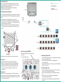
Die Abbildungen zeigen Anwendungsbeispiele für die Verteilung in
Sternstruktur (1) bzw. Baumstruktur (2).
Potentialausgleich und Montage:
Zur Vermeidung gefährlicher Überspannungen (Achtung: Brand-/Lebensgefahr),
müssen die Geräte gemäß EN 60728-11 am Potentialausgleich angeschlossen
werden.
Verwenden Sie den Potenzialausgleichsanschluss am Gerät (3).
Um den Außenleiter der Koaxialkabel am Potentialausgleich anzuschlie-
ßen, verwenden Sie z. B. Erdungsblöcke CFA oder Erdungswinkel QEW am
Eingang und Ausgang des Verstärkers.
Montieren Sie das Gerät auf einer flachen Oberfläche. Verwenden Sie die
dem Gerät beiliegenden Montageschrauben und die Montagelöcher am
Gerät (4).
HF-Anschluss:
Der Verstärker verfügt über F-Buchsen am Eingang und Ausgang.
Schließen Sie den Eingang des Verstärkers am Hausübergabepunkt an.
Verbinden Sie den Ausgang des Verstärkers mit Ihrer Hausverteilung.
Verwenden Sie hierfür ein hochgeschirmtes Koaxialkabel mit einem
F- Anschlussstecker. Passende Kabel und Stecker finden Sie unter
www.axing.com.
Messbuchsen:
Die Messbuchsen (ein- und ausgangsseitig ) mit –20dB sind ebenfalls mit
F-Buchsen versehen, die Messbuchse am Eingang ist bi-direktional ausgelegt.
Diese Messbuchse muss deshalb zur Messung mittels des Jumpers (1a) ein-
bzw. ausgeschaltet (1b) werden.
Einstellungen Downstream:
Stellen Sie mit den Platinenschaltern (2 und 3) Dämpfung und Entzerrung
im Vorwärtsweg (Downstream) ein.
Mit den Jumpern (4 und 5) werden Interstage-Dämpfung und
-Entzerrung eingestellt.
Sie können zum Ausgleichen von Vorentzerrungen eine Kabelnachbildung
(BZU 80-02) einsetzen (6).
Einstellungen Upstream:
Ab Werk ist der Rückkanal (Upstream) aktiv geschaltet. Er kann mit den
Jumpern (7), (8) und (9) passiv geschaltet werden.
Stellen Sie mit dem Platinenschalter (10) die Dämpfung im Rückkanal
ein.
Mit den Jumpern (11 und 12) werden Interstage-Dämpfung und
-Entzerrung im Rückkanal eingestellt.
Mit dem Jumper (13) wird die Dämpfung am Ausgang des Rückkanals
eingestellt.
Betriebsanzeige-LED (POWER):
Der Verstärker verfügt über eine Betriebsanzeige-LED
grün = Betrieb
aus = keine Betriebsspannung
Der Verstärker darf nur wie abgebildet an einer Wand montiert werden!
4 5
32 10
7
8
1a
13 11 12 9
1b
6
Eingang
Messbuchsen
Ausgang
1
2

Manufacturer
AXING AG
Gewerbehaus Moskau
8262 Ramsen
EEA contact address
Bechler GmbH
Am Rebberg 44
78239 Rielasingen
State of the art 2020-05-18
Technical improvements, changes in design, printing- and other errors expected.
Safety advices:
Installation and repairs to the equipment may only be carried out by
technicians observing the current VDE guidelines. No liability will be
assumed in the case of faulty installation and commissioning.
Before opening the equipment pull out the power plug or remove the
power supply, otherwise there is danger of electrocution. This is also
valid for cleaning the equipment or working on the connections.
Only use the mains cable connected to the device. Never replace any
parts or make any modifications on the mains cable. Otherwise there is a
risk of mortal injury for which we cannot be held liable.
Providing that a serviceable fuse exists, the power cord must be pulled
out before changing the fuse. Defective fuses may only be replaced with
standard compliant fuses that have the same nominal value.
The equipment may only be operated in dry rooms. In humid rooms or
outdoors there is danger of short-circuit (caution: risk of fire) or electro-
cution.
The mains plug is used as a disconnecting device from the mains voltage
both during service and in case of danger and must therefore be reacha-
ble and usable at all times. After connection to the mains, the device is in
operation.
Choose the location of installation or mounting such that children may
not play unsupervised near the equipment and its connections. The
location of installation or mounting must allow a safe installation of all
cables connected. Power feeding cables as well as feeder lines may not
be damaged or clamped by objects of any kind. To prevent damage to
your equipment and to avoid possible peripheral damages, the devices
foreseen for wall mounting may only be installed on a flat surface.
Choose a location of installation or mounting which complies to the
protection class IP 54.
Avoid exposure of the equipment to direct sunlight and to other heat
sources (e. g. radiators. other electrical devices, chimney, etc.). Devices
that are equipped with heat sinks or ventilation slots must under no
circum-stances be covered or blocked. Also ensure for a generous air
circulation around the equipment. In this way you avoid possible damage
to the equipment as well as a risk of fire caused by overheating. Abso-
lutely avoid that cables come near any source of heat (e.g. radioators,
other electrical devices, chimney, etc.).
In case of damage, interrupt the power supply immediately.
Do not try to repair the device. This device should only be serviced or
repaired by qualified service personnel. Contact your distributor for more
information.
For disassembly always pull the power supply first and disconnect the
power supply cable from the device.
BVS 14-69
premium-line
CATV amplifiers
Operation instructions
Technical data:
Herewith AXING AG declares that the marked products comply with the valid
guidelines.
WEEE Nr. DE26869279 | Electrical and electronic components must not be
disposed of as residual waste, it must be disposed of separately.
Typ BVS 14-69
EMC according to EN 50083-2, class A
Downstream
Frequency range 85…1006 MHz
Gain 40 dB
Max. output level CSO/CTB
(CENELECraster,41/42ch.60dBIMA)
111 dBµV
Attenuation: adjustable in 1 dB steps 0…15 dB
Equalization: adjustable in 1 dB steps 0…15 dB
Attenuation interstage: pluggable with jumpers 0 | 2 | 4 | 6 dB
Equalization interstage: pluggable with jumpers 0 | 2 | 4 | 6 dB
Return loss ≥ 18 (-1,5 dB/Okt.)
Noise figure typ. <7dB
Upstream
Frequency range 5…65 MHz
Gain 30 dB
Attenuation: adjustable in 1 dB steps 0…15 dB
Equalization interstage: pluggable with jumpers 0 | 3 | 6 | 9 dB
Attenuation interstage: pluggable with jumpers 0 | 6 dB
RF connectors
Type F-female
Test port at in-/output -20 ±2,5 dB/-20 ±1,0 dB
General
Switching power supply 100...240 VAC / 50...60 Hz
Power indicator LED
Power consumption 14 W
Equipotential bonding connection 4 mm²
Operating temperature range
(acc.toEN60065)
-20…+50°C
Dimensions (W × H × D) appr. 182 × 146 × 71 mm
Protection class IP 54

Field of application:
The devices are suited only for amplifying radio and television signals in the
house! If the device is used for other purposes, no warranty is given!
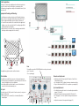
The illustrations show application examples for the distribution in star (1) and
tree structure (2).
Equipotential bonding and Mounting:
To avoid dangerous overvoltages (attention: risk of fire/death), the devices
must be connected to the equipotential bonding according to EN 60728-11.
Use the equipotential bonding connection attached to the device (3).
To connect the outer conductor of the coaxial cable to the equipotential
bonding, use e.g. earth connection blocks CFA or earthing angles QEW at
the input and output of the amplifier.
Mount the device on a flat surface. Use the mounting screws included in
the delivery and the mounting holes of the device (4).
RF Installation:
The amplifier comes with F-female connectors at ist input and output ports.
Connect the input of the amplifier to the interconnection point. Connect the
output of the amplifier to your house distribution.
Use a highly shielded coaxial cable with F connector. Suited cables and
connectors can be found at www.axing.com.
Test ports:
The outside test ports( -20dB ) have also F-female connectors, the test ports at
the input is bi-directional.
This test point has to be activated (1a) or deactivated (1b) with the
adjacent jumper.
Downstream Adjustments:
Adjust the gain and the slope using the PCB switches (2 and 3) in the
forward frequency range.
Use the jumpers (4 and 5) to adjust the interstage attenuation and slope.
Plug in a cable simulator (BZU 80-02) to compensate a pre-emphasis (6).
Upstream Adjustments:
Per default the return path is active. It can be switched passive with the
jumpers (7), (8) and (9).
Adjust the attenuation of the return path with the PCB switch (10).
Use the jumpers (11 and 12) to adjust the interstage attenuation and
slope.
Adjust the attenuation of the output with the jumper (13).
Power indicator LED:
The amplifier comes with a LED (POWER) which shows the operation mode:
green = in operation
off = no power supply
The amplifier may only be monted at a wall as show above.
4 5
32 10
7
8
1a
13 11 12 9
1b
6
Input
Test ports
Output
1
2
-
 1
1
-
 2
2
-
 3
3
-
 4
4


in anderen Sprachen
- English: Axing BVS 14-69
Verwandte Artikel
-
Axing Premium-line BVS 14-69 Operation Instructions
-
Axing premium-line Series Operation Instructions
-
Axing BVS 13-68 CATV amplifier 30 dB Operation Instructions
-
Axing BVS 20-69 Operation Instructions
-
-
-
-
-
Axing basic-line BVS 10-00 Operation Instructions
-