Axing BVS 20-69 Operation Instructions
- Kategorie
- TV-Signalverstärker
- Typ
- Operation Instructions
Dieses Handbuch eignet sich auch für

Hersteller
AXING AG
Gewerbehaus Moskau
8262 Ramsen
EWR-Kontaktadresse
Bechler GmbH
Am Rebberg 44
78239 Rielasingen
Stand 2017-07-20
Konstruktions- und Typenänderung vorbehalten - keine Haftung für Druckfehler.
Sicherheitshinweise:
Die Installation des Gerätes und Reparaturen am Gerät sind
ausschließlich vom Fachmann unter Beachtung der geltenden VDE-
Richtlinien durchzuführen. Bei nicht fachgerechter Installation und
Inbetriebnahme wird keine Haftung übernommen.
Vor Öffnen des Gerätes Netzstecker ziehen bzw. Stromzuführung
entfernen, andernfalls besteht Lebensgefahr. Dies gilt auch, wenn Sie das
Gerät reinigen oder an den Anschlüssen arbeiten.
Verwenden Sie nur das am Gerät angeschlossene Netzkabel. Es dürfen
am Netzkabel auf keinen Fall Teile ausgetauscht oder Veränderungen
vorgenommen werden. Es besteht sonst Lebensgefahr, für die keine
Haftung übernommen wird.
Sofern eine austauschbare Sicherung vorhanden ist, ist vor dem Wechsel
der Sicherung der Netzstecker zu ziehen. Defekte Sicherungen nur durch
normgerechte Sicherungen des gleichen Nennwertes ersetzen.
Das Gerät darf nur in trockenen Räumen betrieben werden. In feuchten
Räumen oder im Freien besteht die Gefahr von Kurzschlüssen (Achtung:
Brandgefahr) oder elektrischem Schlägen (Achtung: Lebensgefahr).
Planen Sie den Montage- bzw. Aufstellort so, dass Sie in
Gefahrensituationen den Netzstecker leicht erreichen und aus
der Steckdose ziehen können. Wählen Sie den Montage- bzw.
Aufstellort so, dass Kinder nicht unbeaufsichtigt am Gerät und dessen
Anschlüssen spielen können. Der Montage- bzw. Aufstellort muss
eine sichere Verlegung aller angeschlossenen Kabel ermöglichen.
Stromversorgungskabel sowie Zuführungskabel dürfen nicht durch
irgendwelche Gegenstände beschädigt oder gequetscht werden.
Wählen Sie einen Montage- bzw. Aufstellungsort, der der Schutzklasse
IP54 entspricht.
Setzen Sie das Gerät niemals direkter Sonneneinstrahlung aus und
vermeiden Sie die direkte Nähe von Wärrmequellen (z. B. Heizkörper,
andere Elektrogeräte, Kamin etc.) Bei Geräten, die Kühlkörper oder
Lüftungsschlitze haben, muss daher unbedingt darauf geachtet werden,
dass diese keinesfalls abgedeckt oder verbaut werden. Sorgen Sie
außerdem für eine großzügig bemessene Luftzirkulation um das Gerät.
Damit verhindern Sie mögliche Schäden am Gerät sowie Brandgefahr
durch Überhitzung. Achten Sie unbedingt darauf, dass Kabel nicht in die
Nähe von Wärmequellen (z.B. Heizkörper, andere Elektrogeräte, Kamin
etc.) kommen.
BVS 20-66 | 20-69
premium-line
CATV-Verstärker
Betriebsanleitung
Technische Daten:
Ihr Gerät ist mit dem WEEE-Symbol markiert (Waste Electronics and Electrical
Equipment). Dies bedeutet, dass elektrische und elektronische Komponenten
nicht mit dem Restmüll entsorgt werden dürfen. Gebrauchte elektrische und
elektronische Komponenten sind separat zu entsorgen.
WEEE Nr.
DE14023300
Artikel
BVS 20-69 BVS 20-66
EMV gemäß EN 50083-2, Klasse A
Downstream-Frequenzbereich 85…1006 MHz
Downstream-Verstärkung 38 dB
Downstream-Dämpfung: stufenloses Stellglied 0…15 dB
Downstream-Entzerrung: stufenloses Stellglied 0…15 dB
Downstream-Dämpfung Interstage: mit Jumpern steckbar 0 | 2 | 4 | 6 dB
Downstream-Entzerrung Interstage: mit Jumpern steckbar 0 | 2 | 4 | 6 dB
Downstream-Rückflussdämpfung ≥ 18 dB (-1,5 dB/Okt.)
Downstream-Rauschmaß typ ≤ 5,5 dB
Max. Downstream-Ausgangspegel CSO/CTB
1
107 dBµV
Upstream-Frequenzbereich
5…65 MHz
2
Upstream-Verstärkung 30 dB
Upstream-Dämpfung: stufenloses Stellglied 0…15 dB
Upstream-Dämpfung Interstage: mit Jumpern steckbar 0 | 6 dB
Upstream-Entzerrung Interstage: mit Jumpern steckbar 0 | 3 | 6 | 9 dB
Upstream-Rauschmaß ≤ 7 dB
Messbuchse Ein-/Ausgangsseite -20 ±2,5 dB | -20 ±1,0 dB
Netzteil 100...240 V~/50...60 Hz 30...65 V~/50...60 Hz
Leistungsaufnahme 10 W
Umgebungstemperaturbereich (gemäß EN 60065) -20…+50°C
Erdungsanschluss Erdungsklemme
Maße (B × H × T) ca. 195 × 90 × 55 mm
Schutzklasse IP 54
1
CENELEC Raster 41 ch. 60 dB IMA
2
Dadurch kein VHF I im Vorwärtsweg möglich

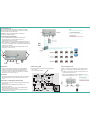
Verwendungsbereich:
Die Geräte sind ausschließlich für den Einsatz zum Verstärken von Radio-
und Fernsehsignalen im Haus geeignet! Wird das Gerät für andere Einsätze
verwendet, wird keine Garantie übernommen!
Die Abbildung zeigt ein Anwendungsbeispiel für die Verteilung in
Sternstruktur(1) und Baumstruktur (2).
Potentialausgleich und Montage:
Zur Vermeidung gefährlicher Überspannungen (Achtung: Brand-/
Lebensgefahr), müssen die Geräte gemäß EN 60728-11 am
Potentialausgleich angeschlossen werden.
Verwenden Sie den am Gerät angebrachten Potenzialausgleichsanschluss (3).
Um den Außenleiter der Koaxialkabel am Potentialausgleich anzuschließen,
verwenden Sie z. B. Erdungsblöcke CFA oder Erdungswinkel QEW am Eingang
und Ausgang des Verstärkers.
Verwenden Sie die dem Gerät beiliegenden Montageschrauben und die
Montagelöcher an den Geräten (4).
HF-Anschluss:
Schließen Sie den Eingang des Verstärkers am Hausübergabepunkt an.
Verbinden Sie den Ausgang des Verstärkers mit Ihrer Hausverteilung.
Verwenden Sie hierfür ein hochgeschirmtes Koaxialkabel mit einem
F- Anschlussstecker. Passende Kabel und Stecker finden Sie im aktuellen
AXING-Katalog oder unter www.axing.com.
Messbuchse:
Die Messbuchse am Eingang ist bi-direktional ausgelegt. Diese Messbuchse
muss deshalb mit Hilfe des Jumpers (ON/OFF) ein- bzw. ausgeschaltet
werden.
Einstellungen von Dämpfung und Entzerrung:
Stellen Sie mit den Reglern (DS 1) und (DS 2) Dämpfung und Entzerrung im
Vorwärtsweg ein.
Mit dem Regler (US) wird die Dämpfung des Rückkanals vor der
Verstärkerstufe eingestellt.
Mit den Jumpern (DS J1 und DS J2) werden Interstage-Dämpfung und
-Entzerrung im Vorwärtsbereich eingestellt.
Mit den Jumpern (US J1 und US J2) werden Interstage-Entzerrung und
-Dämpfung im Rückkanal eingestellt.
1
2
44
3
Eingang Ausgang
Messbuchsen
Betriebsanzeige-LED:
Der Verstärker verfügt über eine Betriebsanzeige-LED (POWER):
grün = Betrieb
aus = keine Betriebsspannung
Fernspeisung BVS 20-66:
Der BVS 20-66 wird über die Koaxialleitung versorgt. Mit dem Jumper PS
stellen Sie ein, ob der Verstärker am Eingang oder Ausgang ferngespeist
wird.
Installieren Sie dementsprechend am Ein- oder Ausgang des BVS 20-66
eine Stromein speiseweiche TZU 15-01.
Schließen Sie daran mit Hilfe des Fernspeisekabels BZU150-00 einen
Fernspeisetransformator BZU 100-00 an.

Manufacturer
AXING AG
Gewerbehaus Moskau
8262 Ramsen
EWR contact adress
Bechler GmbH
Am Rebberg 44
78239 Rielasingen
State of the art 2017-07-20
Technical changes, design modifications, errors and misprints are subject to
change without prior notice.
Safety advices:
Installation and repairs to the equipment may only be carried out by
technicians observing the current VDE guidelines. No liability will be
assumed in the case of faulty installation and commissioning.
Before opening the equipment pull out the power plug or remove the
power supply, otherwise there is danger of electrocution. This is also
valid for cleaning the equipment or working on the connections.
Only use the mains cable connected to the device. Never replace any
parts or make any modifications on the mains cable. Otherwise there is a
risk of mortal injury for which we cannot be held liable.
Providing that a serviceable fuse exists, the power cord must be pulled
out before changing the fuse. Defective fuses may only be replaced with
standard compliant fuses that have the same nominal value.
The equipment may only be operated in dry rooms. In humid rooms
or outdoors there is danger of short-circuit (caution: risk of fire) or
electrocution.
Choose the location of installation or mounting so that the power plug
can be reached and pulled out of the socket easily in case of danger.
Choose the location of installation or mounting such that children may
not play unsupervised near the equipment and its connections. The
location of installation or mounting must allow a safe installation of all
cables connected. Power feeding cables as well as feeder lines may not
be damaged or clamped by objects of any kind. To prevent damage to
your equipment and to avoid possible peripheral damages, the devices
foreseen for wall mounting may only be installed on a flat surface.
Choose a location of installation or mounting which complies to the
protection class IP 54.
Avoid exposure of the equipment to direct sunlight and to other heat
sources (e. g. radiators. other electrical devices, chimney, etc.). Devices
that are equipped with heat sinks or ventilation slots must under no
circum-stances be covered or blocked. Also ensure for a generous
air circulation around the equipment. In this way you avoid possible
damage to the equipment as well as a risk of fire caused by overheating.
Absolutely avoid that cables come near any source of heat (e.g.
radioators, other electrical devices, chimney, etc.).
BVS 20-66 | 20-69
premium-line
CATV amplifiers
Operation instructions
Technical data:
Your device is marked with the WEEE symbol (Waste Electronics and
Electrical Equipment). This means that the electrical and electronic
components must not be disposed of as residual waste. Used electrical and
electronic components must be disposed of separately.
WEEE Nr.
DE14023300
Article
BVS 20-69 BVS 20-66
EMC according to EN 50083-2, class A
Downstream frequency range 85…1006 MHz
Downstream gain 38 dB
Attenuation: continuously adjustable 0…15 dB
Equalization: continuously adjustable 0…15 dB
Attenuation interstage: pluggable with jumpers 0 | 2 | 4 | 6 dB
Equalization interstage: pluggable with jumpers 0 | 2 | 4 | 6 dB
Downstream return loss ≥ 18 dB (-1,5 dB/oct.)
Downstream noise figure typ. ≤ 5,5 dB
Max. downstream output level CSO/CTB
1
107 dBµV
Upstream frequency range
5…65 MHz
2
Upstream gain 30 dB
Attenuation: continuously adjustable (actuator) 0…15 dB
Upstream sttenuation interstage: pluggable with jumpers 0 | 6 dB
Upstream equalization interstage: pluggable with jumpers 0 | 3 | 6 | 9 dB
Upstream noise figure ≤ 7 dB
Test port at in-/output -20 ±2,5 dB | -20 ±1,0 dB
Power supply 100...240 V~/50...60 Hz 30...65 V~/50...60 Hz
Power consumption 10 W
Ambient temperature range (acc. to EN 60065) -20…+50°C
Ground connection Ground terminal
Dimensions (W × H × D) appr. 195 × 90 × 55 mm
Protection class IP 54
1
CENELEC Raster 41 ch. 60 dB IMA
2
VHF I in forward path is not possible

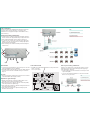
Field of application:
The devices are suited only for amplifying radio and television signals in the
house! If the device is used for other purposes, no warranty is given!
The illustration shows an application example for the distribution in star (1)
and tree structure (2).
Equipotential bonding and Mounting:
To avoid dangerous overvoltages (attention: risk of fire/death), the devices
must be connected to the equipotential bonding according to EN 60728-11.
Use the equipotential bonding connection attached to the device (3).
To connect the outer conductor of the coaxial cable to the equipotential
bonding, use e.g. earth connection blocks CFA or earthing angles QEW at
the input and output of the amplifier.
Use the mounting screws included in the delivery and the mounting holes
of the devices (4).
1
2
44
3
Input Output
Test ports
Remote power feeding of BVS 20-66:
The BVS 20-66 is supplied over the coaxial cable. The jumper (PS) is used to
decide between remote power supply at the input (position „Eingang“) or
at the output (position „Ausgang“).
Install according to this a power inserter TZU15-01 at the input or at the
output of the amplifier.
Connect a remote feed transformer BZU 100-00 via a remote feed cable
BZU 150-00 to the power inserter.
RF Installation:
Connect the input of the amplifier to the interconnection point. Connect the
output of the amplifier to your house distribution.
Use a highly shielded coaxial cable with an F connector. Suitable cables and
connectors can be found in the current AXING catalogue or under www.
axing.com.
Test port:
The test port at the input is bi-directional. This test port has to be activated
or deactivated with the adjacent jumper (ON/OFF).
Adjustments of gain and slope:
Adjust the gain and the slope (continuously variable) with the control
buttons (DS 1 and DS 2) in the forward frequency range.
With control button (US) one adjusts the gain (also continuously variable)
of the return path before the amplifier stage.
Use the jumpers (DS J1 and DS J2) to adjust the interstage attenuation and
slope in the forward frequency range.
Use the jumpers (US J1 and US J2) to adjust the interstage slope and
attenuation of the return path.
Power indicator LED:
The amplifier comes with a LED (POWER) which shows the operation mode:
green = in operation
out = no power supply
-
 1
1
-
 2
2
-
 3
3
-
 4
4


Axing BVS 20-69 Operation Instructions
- Kategorie
- TV-Signalverstärker
- Typ
- Operation Instructions
- Dieses Handbuch eignet sich auch für
in anderen Sprachen
- English: Axing BVS 20-69
Verwandte Artikel
-
Axing Premium-line BVS 14-69 Operation Instructions
-
Axing premium-line Series Operation Instructions
-
-
-
Axing BVS 13-68 CATV amplifier 30 dB Operation Instructions
-
-
-
-
Axing basic-line BVS 10-00 Operation Instructions
-