Axing premium-line TVS 31-00 Operation Instructions
- Typ
- Operation Instructions

Hersteller
AXING AG
Gewerbehaus Moskau
8262 Ramsen
EWR-Kontaktadresse
Bechler GmbH
Am Rebberg 44
78239 Rielasingen
Stand 2017
-06-09
Technische Änderungen, Änderungen im Design, Druckfehler und Irrtümer
vorbehalten.
Sicherheitshinweise:
Die Installation des Gerätes und Reparaturen am Gerät sind
ausschließlich vom Fachmann unter Beachtung der geltenden VDE-
Richtlinien durchzuführen. Bei nicht fachgerechter Installation und
Inbetriebnahme wird keine Haftung übernommen.
Vor Öffnen des Gerätes Netzstecker ziehen bzw. Stromzuführung
entfernen, andernfalls besteht Lebensgefahr. Dies gilt auch, wenn Sie das
Gerät reinigen oder an den Anschlüssen arbeiten.
Verwenden Sie nur das am Gerät angeschlossene Netzkabel. Es dürfen
am Netzkabel auf keinen Fall Teile ausgetauscht oder Veränderungen
vorgenommen werden. Es besteht sonst Lebensgefahr, für die keine
Haftung übernommen wird.
Sofern eine austauschbare Sicherung vorhanden ist, ist vor dem Wechsel
der Sicherung der Netzstecker zu ziehen. Defekte Sicherungen nur durch
normgerechte Sicherungen des gleichen Nennwertes ersetzen.
Das Gerät darf nur in trockenen Räumen betrieben werden. In feuchten
Räumen oder im Freien besteht die Gefahr von Kurzschlüssen (Achtung:
Brandgefahr) oder elektrischem Schlägen (Achtung: Lebensgefahr).
Planen Sie den Montage- bzw. Aufstellort so, dass Sie in
Gefahrensituationen den Netzstecker leicht erreichen und aus
der Steckdose ziehen können. Wählen Sie den Montage- bzw.
Aufstellort so, dass Kinder nicht unbeaufsichtigt am Gerät und dessen
Anschlüssen spielen können. Der Montage- bzw. Aufstellort muss
eine sichere Verlegung aller angeschlossenen Kabel ermöglichen.
Stromversorgungskabel sowie Zuführungskabel dürfen nicht durch
irgendwelche Gegenstände beschädigt oder gequetscht werden.
Wählen Sie einen Montage- bzw. Aufstellungsort, der der Schutzklasse IP
54 entspricht.
Setzen Sie das Gerät niemals direkter Sonneneinstrahlung aus und
vermeiden Sie die direkte Nähe von Wärrmequellen (z. B. Heizkörper,
andere Elektrogeräte, Kamin etc.) Bei Geräten, die Kühlkörper oder
Lüftungsschlitze haben, muss daher unbedingt darauf geachtet werden,
dass diese keinesfalls abgedeckt oder verbaut werden. Sorgen Sie
außerdem für eine großzügig bemessene Luftzirkulation um das Gerät.
Damit verhindern Sie mögliche Schäden am Gerät sowie Brandgefahr
durch Überhitzung. Achten Sie unbedingt darauf, dass Kabel nicht in die
Nähe von Wärmequellen (z.B. Heizkörper, andere Elektrogeräte, Kamin
etc.) kommen.
TVS 31-00
premium-line
Mehrbereichsverstärker
Betriebsanleitung
Technische Daten:
Ihr Gerät ist mit dem WEEE-Symbol markiert (Waste Electronics and Electrical
Equipment). Dies bedeutet, dass elektrische und elektronische Komponenten
nicht mit dem Restmüll entsorgt werden dürfen. Gebrauchte elektrische und
elektronische Komponenten sind separat zu entsorgen.
WEEE Nr.
DE26869279
Artikel TVS 31-00
Eingang ANT1 Frequenzbereich 174...230 MHz
Verstärkung 45 dB
Eingang ANT2/3 Frequenzbereich 470...862 MHz
Verstärkung 45 dB
Eingang BI/FM Frequenzbereich 47...108 MHz
Verstärkung 25 dB
Eingang Ext. Frequenzbereich 174...862 MHz
Verstärkung 30 dB
Einstellbare Dämpfung 0…20 dB
Max. Ausgangspegel 3rd order max.
1
105 dBµV
Messbuchse an der Ausgangsseite -20 dB
Schaltnetzteil 90…250 V~ | 47…63 Hz
Leistungsaufnahme 8 W
Umgebungstemperaturbereich (gemäß EN 60065) -20…+50°C
Ausgangsspannung für Fernspeisung von Vorverstärkern 12 V =/100 mA
Maße (B × H × T) ca. 190 × 140 × 75 mm
Schutzklasse IP 20
1
EN 60728-5

Verwendungsbereich:
Die Geräte sind ausschließlich für den Einsatz zum Verstärken sowie Verteilen
von Radio- und Fernsehsignalen im Haus geeignet! Wird das Gerät für andere
Einsätze verwendet, wird keine Garantie übernommen!
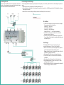
Potentialausgleich und Montage:
Zur Vermeidung gefährlicher Überspannungen (Achtung: Brand-/Lebensgefahr), müssen die Geräte gemäß EN 60728-11 am Potentialausgleich angeschlossen
werden.
Verwenden Sie den am Gerät angebrachten Potenzialausgleichsanschluss (1).
Um den Außenleiter der Koaxialkabel am Potentialausgleich anzuschließen, verwenden Sie z. B. QEW-Erdungswinkel oder CFA-Erdungsblöcke am Eingang
und Ausgang des Verstärkers.
Verwenden Sie die dem Gerät beiliegenden Montageschrauben und die Montagelöcher an den Geräten (2).
HF-Anschluss:
Schließen Sie die Eingänge des Verstärkers an einer für den jeweiligen
Eingang geeigneten Antenne/Signalquelle an.
Eingang ANT 1 VHF Antenne
Eingang ANT2/3 UHF Antenne
Eingang BI/FM VHF I/UKW-Antenne
Eingang EXT VHF+UHF z.B. HÜP eines Kabelanschlusses
Verbinden Sie den Ausgang des Verstärkers mit den verwendeten
Antennensteckdosen oder Verteilern.
Verwenden Sie hochgeschirmte Koaxialkabel mit F- Anschlussstecker.
Passende Kabel und Stecker finden Sie im aktuellen AXING-Katalog oder
unter www.axing.com.
Einstellungen:
Für die Eingänge ANT 1 bis 3 können Sie eine Fernspeisung der
angeschlossenen Antenne von 12 V/max. 100 mA einschalten.
Drücken Sie dazu den Taster (3). Die dazugehörige LED (4) signalisiert
grün, dass die Fernspeisespannung am Eingang ansteht.
Hinweis: Bei Überschreiten der 100mA wechselt die grüne LED auf Rot
und die DC-Versorgung wird abgeschaltet.
Die Eingänge ANT1 und 2 können zu- oder abgeschaltet werden.
Stellen Sie den Schalter (5) auf die obere Position, um die Antenne
zuzuschalten.
Mit den Kanalstellern (6) können Sie bis zu 10 Kanäle einstellen.
Mit den Dämpfungsstellern (7) können Sie die Pegel der 10 Kanäle
unabhängig voneinander einstellen.
Mit den Pegelstellern (8) können Sie die Eingangspegel des Eingangs B1/
FM und des Eingangs EXT VHF+UHF einstellen.

Manufacturer
AXING AG
Gewerbehaus Moskau
8262 Ramsen
EEA contact address
Bechler GmbH
Am Rebberg 44
78239 Rielasingen
State of the art 2017-06-09
Technical changes, design modifications, errors and misprints are subject to
change without prior notice.
Safety advices:
Installation and repairs to the equipment may only be carried out by
technicians observing the current VDE guidelines. No liability will be
assumed in the case of faulty installation and commissioning.
Before opening the equipment pull out the power plug or remove the
power supply, otherwise there is danger of electrocution. This is also
valid for cleaning the equipment or working on the connections.
Only use the mains cable connected to the device. Never replace any
parts or make any modifications on the mains cable. Otherwise there is a
risk of mortal injury for which we cannot be held liable.
Providing that a serviceable fuse exists, the power cord must be pulled
out before changing the fuse. Defective fuses may only be replaced with
standard compliant fuses that have the same nominal value.
The equipment may only be operated in dry rooms. In humid rooms
or outdoors there is danger of short-circuit (caution: risk of fire) or
electrocution.
Choose the location of installation or mounting so that the power plug
can be reached and pulled out of the socket easily in case of danger.
Choose the location of installation or mounting such that children may
not play unsupervised near the equipment and its connections. The
location of installation or mounting must allow a safe installation of all
cables connected. Power feeding cables as well as feeder lines may not
be damaged or clamped by objects of any kind. To prevent damage to
your equipment and to avoid possible peripheral damages, the devices
foreseen for wall mounting may only be installed on a flat surface.
Choose a location of installation or mounting which complies to the
protection class IP 54.
Avoid exposure of the equipment to direct sunlight and to other heat
sources (e. g. radiators. other electrical devices, chimney, etc.). Devices
that are equipped with heat sinks or ventilation slots must under no
circum-stances be covered or blocked. Also ensure for a generous
air circulation around the equipment. In this way you avoid possible
damage to the equipment as well as a risk of fire caused by overheating.
Absolutely avoid that cables come near any source of heat (e.g.
radioators, other electrical devices, chimney, etc.).
TVS 31-00
premiu-line
Multiband amplifier
Operation instructions
Technical data:
Your device is marked with the WEEE symbol (Waste Electronics and
Electrical Equipment). This means that the electrical and electronic
components must not be disposed of as residual waste. Used electrical and
electronic components must be disposed of separately.
WEEE Nr.
DE26869279
Article TVS 31-00
Input ANT1 frequency range 174...230 MHz
Gain 45 dB
Input ANT2/3 frequency range 470...862 MHz
Gain 45 dB
Input BI/FM frequency range 47...108 MHz
Gain 25 dB
Input Ext. frequency range 174...862 MHz
Gain 30 dB
Adjustable attenuator 0…20 dB
Max. output level 3rd order max.
1
105 dBµV
Test port at the output -20 dB
Switching mode power supply 90…250 V~ | 47…63 Hz
Power consumption 8 W
Ambient temperature range (acc. to EN 60065) -20…+50°C
Output voltage to remote-feed preamplifiers 12 V =/100 mA
Dimensions (W × H × D) appr. 190 × 140 × 75 mm
Protection class IP 20
1
EN 60728-5

Field of application:
The devices are suitable for amplifying and distributing radio and television
signals in the house only! If the device is used for other purposes, no warranty
will be given!
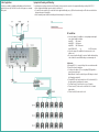
Equipotential bonding and Mounting:
To avoid dangerous overvoltages (attention: risk of fire/death), the devices must be connected to the equipotential bonding according to EN 60728-11.
Use the equipotential bonding connection attached to the device (1).
To connect the outer conductor of the coaxial cable to the equipotential bonding, use e.g. QEW earth connection angles or CFA earth connection blocks at
the input and output of the amplifier.
Use the mounting screws included in the delivery and the mounting holes of the devices (2).
RF Installation:
Connect the inputs of the amplifier to a corresponding antenna/signal
source that is suitable for the input.
Input ANT 1 VHF antenna
Input ANT2/3 UHF antenna
Input BI/FM VHF I/FM antenna
Input EXT VHF+UHF e.g. for CATV connection
Connect the output of the amplifier to the antenna sockets or the
splitters used.
Use screened coaxial cables with F connectors. Suitable cables and plugs
can be found in the current AXING catalogue or at www.axing.com.
Adjustments:
For the inputs ANT 1 to 3, a remote feeding of the connected antenna with
12 V/max. 100 mA can be switched on.
For this, press the buttons (3). The corresponding LED (4) signalizes a
remote current on the input.
Note: When the 100 mA is exceeded, the green LED changes to red and
the DC supply is switched off.
The inputs ANT1 and 2 can be switched on or off. Set the switches (5) to
the upper position for switching on the antenna.
The channel control (6) can be used to set up to 10 channels.
The level controls (7) can be used to set the level of the 10 channels
independently.
The level controls (8) can be used to set th
-
 1
1
-
 2
2
-
 3
3
-
 4
4


Axing premium-line TVS 31-00 Operation Instructions
- Typ
- Operation Instructions
in anderen Sprachen
- English: Axing premium-line TVS 31-00
Verwandte Papiere
-
Axing basic-line Series Operation Instructions
-
Axing TVS 1-00 Operation Instructions
-
-
Axing premium-line Series Operation Instructions
-
-
-
-
-
-
