Hersteller
AXING AG
Gewerbehaus Moskau
8262 Ramsen
EWR-Kontaktadresse
Bechler GmbH
Am Rebberg 44
78239 Rielasingen
Stand 2018-04-06
Technische Verbesserungen, Änderungen im Design, Druckfehler und Irrtümer
vorbehalten.
Sicherheitshinweise:
Die Installation des Geräts und Reparaturen am Gerät sind ausschließlich
vom Fachmann unter Beachtung der geltenden VDE-Richtlinien
durchzuführen. Bei nicht fachgerechter Installation und Inbetriebnahme
wird keine Haftung übernommen.
Vor Öffnen des Gerätes Netzstecker ziehen bzw. Stromzuführung
entfernen, andernfalls besteht Lebensgefahr. Dies gilt auch, wenn Sie das
Gerät reinigen oder an den Anschlüssen arbeiten.
Verwenden Sie nur das am Gerät angeschlossene Netzkabel. Es dürfen
am Netzkabel auf keinen Fall Teile ausgetauscht oder Veränderungen
vorgenommen werden. Es besteht sonst Lebensgefahr, für die keine
Haftung übernommen wird.
Sofern eine austauschbare Sicherung vorhanden ist, ist vor dem Wechsel
der Sicherung der Netzstecker zu ziehen. Defekte Sicherungen nur durch
normgerechte Sicherungen des gleichen Nennwertes ersetzen.
Das Gerät darf nur in trockenen Räumen betrieben werden. In feuchten
Räumen oder im Freien besteht die Gefahr von Kurzschlüssen (Achtung:
Brandgefahr) oder elektrischem Schlägen (Achtung: Lebensgefahr).
Planen Sie den Montage- bzw. Aufstellort so, dass Sie in
Gefahrensituationen den Netzstecker leicht erreichen und aus
der Steckdose ziehen können. Wählen Sie den Montage- bzw.
Aufstellort so, dass Kinder nicht unbeaufsichtigt am Gerät und dessen
Anschlüssen spielen können. Der Montage- bzw. Aufstellort muss
eine sichere Verlegung aller angeschlossenen Kabel ermöglichen.
Stromversorgungskabel sowie Zuführungskabel dürfen nicht durch
irgendwelche Gegenstände beschädigt oder gequetscht werden.
Wählen Sie einen Montage- bzw. Aufstellungsort, an dem unter keinen
Umständen Flüssigkeiten oder Gegenstände in das Gerät gelangen
können (z. B. Kondenswasser, Dachundichtigkeiten, Gießwasser etc.)
Setzen Sie das Gerät niemals direkter Sonneneinstrahlung aus und
vermeiden Sie die direkte Nähe von Wärrmequellen (z. B. Heizkörper,
andere Elektrogeräte, Kamin etc.) Bei Geräten, die Kühlkörper oder
Lüftungsschlitze haben, muss daher unbedingt darauf geachtet werden,
dass diese keinesfalls abgedeckt oder verbaut werden. Sorgen Sie
außerdem für eine großzügig bemessene Luftzirkulation um das Gerät.
Damit verhindern Sie mögliche Schäden am Gerät sowie Brandgefahr
durch Überhitzung. Achten Sie unbedingt darauf, dass Kabel nicht in die
Nähe von Wärmequellen (z.B. Heizkörper, andere Elektrogeräte, Kamin
etc.) kommen.
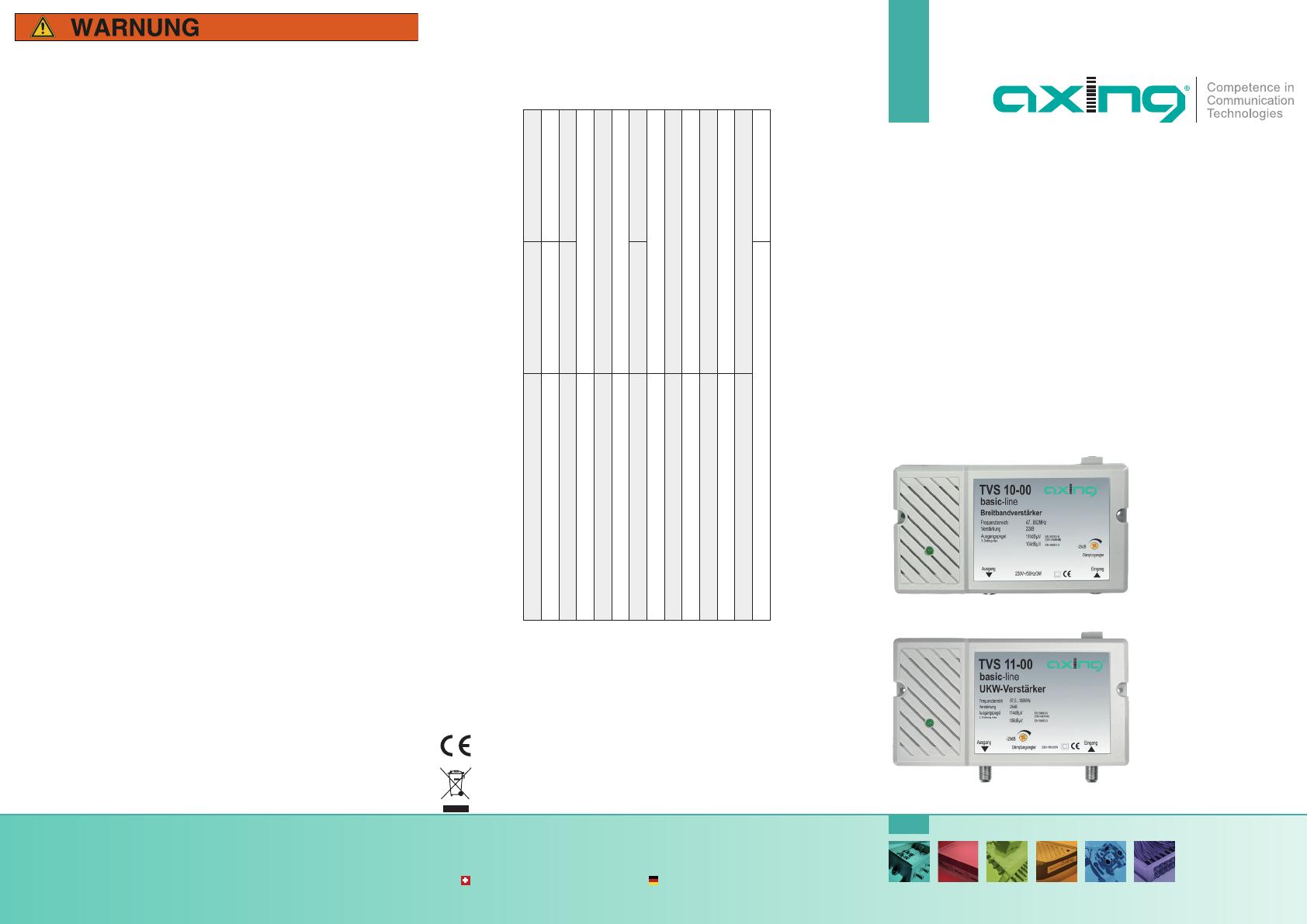
TVS 10-00
TVS 11-00
basic-line
Breitbandverstärker
FM-Verstärker
Betriebsanleitung
Technische Daten:
Artikel
TVS 10-00 TVS 11-00
Frequenzbereich 47…862 MHz 87,5…108 MHz
Verstärkung 22 dB 25 dB
Dämpfung, einstellbar 20 dB
Rauschmaß ≤ 7 dB
Max. Ausgangspegel (3rd order max.
1
)
108 dBµV
HF-Anschlüsse IEC F
Integriertes Netzteil 230 V~ / 50 Hz
Leistungsaufnahme 3 W
Umgebungstemperaturbereich (gemäß EN 60065) -20…+50°C
Potentialausgleichanschluss 4 mm²
Maße (B × H × T) ca. 160 × 100 × 45 mm
Schutzklasse IP 20
1
EN50083-3 60dB KMA
Hiermit erklärt die AXING AG, dass die gekennzeichneten Produkte den
geltetenden Richtlinien entsprechen. Sie finden die vollständige EU-
Konformitätserklärung zum Download indem Sie auf www.axing.com im
Suchfeld den Artikel eingeben.
WEEE Nr. DE26869279 | Elektrische und elektronische Komponenten nicht
mit dem Restmüll, sondern separat entsorgen.


