Axing premium-line ONX 1550-01 Operation Instructions
- Typ
- Operation Instructions

Hersteller
AXING AG
Gewerbehaus Moskau
8262 Ramsen
EWR-Kontaktadresse
Bechler GmbH
Am Rebberg 44
78239 Rielasingen
Stand 2019-12-04
Technische Verbesserungen, Änderungen im Design, Druckfehler und Irrtümer
vorbehalten.
Sicherheitshinweise:
Das Gerät darf nur von Personal installiert und in Betrieb genommen
werden, das die erforderlichen Schulungen über den Umgang mit opti-
schen und elektrischen Geräten erhalten hat und über Sicherheitsanwei-
sungen für den Umgang mit Lasern unterrichtet worden ist.
Installation und Reparaturen am Gerät sind ausschließlich vom Fach-
mann unter Beachtung der geltenden Richtlinien durchzuführen. Bei
nicht fachgerechter Installation und Inbetriebnahme wird keine Haftung
übernommen.
Vor der Handhabung oder dem Öffnen des Gerätes Netzstecker ziehen
bzw. Stromzuführung entfernen, andernfalls besteht Lebensgefahr. Dies
gilt auch, wenn Sie das Gerät reinigen oder an den Anschlüssen arbeiten.
Verwenden Sie nur das am Gerät angeschlossene Netzkabel. Es dürfen
am Netzkabel auf keinen Fall Teile ausgetauscht oder Veränderungen
vorgenommen werden. Es besteht sonst Lebensgefahr, für die keine
Haftung übernommen wird.
Sofern eine austauschbare Sicherung vorhanden ist, ist vor dem Wechsel
der Sicherung der Netzstecker zu ziehen. Defekte Sicherungen nur durch
normgerechte Sicherungen des gleichen Nennwertes ersetzen.
Das Gerät darf nur in trockenen Räumen betrieben werden. In feuchten
Räumen oder im Freien besteht die Gefahr von Kurzschlüssen (Achtung:
Brandgefahr) oder elektrischem Schlägen (Achtung: Lebensgefahr).
Wählen Sie einen Montage- bzw. Aufstellungsort, der der Schutzklasse
IP54 entspricht.
Planen Sie den Montage- bzw. Aufstellort so, dass Sie in
Gefahrensituationen den Netzstecker leicht erreichen und aus
der Steckdose ziehen können. Wählen Sie den Montage- bzw.
Aufstellort so, dass Kinder nicht unbeaufsichtigt am Gerät und dessen
Anschlüssen spielen können. Der Montage- bzw. Aufstellort muss
eine sichere Verlegung aller angeschlossenen Kabel ermöglichen.
Stromversorgungskabel sowie Zuführungskabel dürfen nicht beschädigt
oder gequetscht werden.
Setzen Sie das Gerät niemals direkter Sonneneinstrahlung aus und
vermeiden Sie die direkte Nähe von Wärrmequellen (z. B. Heizkörper,
andere Elektrogeräte, Kamine etc.).
Bei Geräten, die Kühlkörper oder Lüftungsschlitze haben, muss unbedingt
darauf geachtet werden, dass diese keinesfalls abgedeckt oder
verbaut werden. Sorgen Sie außerdem für eine großzügig bemessene
Luftzirkulation um das Gerät. Damit verhindern Sie mögliche Schäden
am Gerät sowie Brandgefahr durch Überhitzung. Achten Sie unbedingt
darauf, dass Kabel nicht in die Nähe von Wärmequellen (z.B. Heizkörper,
andere Elektrogeräte, Kamine etc.) kommen.
ONX 1550-01
premium-line
Micro Fibre Node
Betriebsanleitung
Technische Daten:
Hiermit erklärt die AXING AG, dass die gekennzeichneten Produkte den
geltetenden Richtlinien entsprechen.
WEEE Nr. DE26869279 | Elektrische und elektronische Komponenten nicht
mit dem Restmüll, sondern separat entsorgen.
Typ ONX155001
Eingang
Optischer Anschluss 1 × SC/APC
Optische Rückflussdämpfung ≥ 40 dB
Downstream
Wellenlänge 1540...1560 nm
Optischer Eingangspegel -8…+1 dBm
Optischer OLC-Bereich 0…-6 dBm
Frequenzbereich 85…1218 MHz
Ausgangspegel @ OMI 3.5% (flat) 94 dBµV
CSO (Cenelec 42, OMI 3.5%) 60 dBc
CTB (Cenelec 42, OMI 3.5%) 60 dBc
Welligkeit ±1 dB
Rauschstromdichte 7,4 pA/√Hz
Entzerrung Interstage: mit Jumpern steckbar 0/2/4/6 dB
Rückflussdämpfung ≥ 18 dB (-1,5 dB/Oktave)
Messbuchse -20 dB
Upstream
Laser-Typ DFB
Wellenlänge 1310 nm
Laser-Modus (schaltbar) CW/Burst
Optischer Ausgangspegel +3 ±1 dBm
Laser Einschaltzeit ≤ 1.3 µsec
HF-Pegel für Laser on | off 67 dBµV | 58 dBµV
Frequenzbereich 5…65 MHz
Welligkeit ±1 dB
Rückflussdämpfung ≥ 18 dB (-1,5 dB/Oktave)
Dämpfung: schaltbar in 2dB Schritten 0…30 dB
Messbuchse -20 dB
HF-Anschlüsse
Typ F-Buchse
Allgemein
Betriebsspannung 100...240 VAC
Leistungsaufnahme 6 W
Betriebstemperaturbereich 0...50 °C
Maße (B × H × T) ca. 195 x 90 x 55 mm

Verwendungsbereich:
Die Geräte sind ausschließlich für optische FTTH/FTTB-Anwendungen oder
RFoG-Netze geeignet! Wird das Gerät für andere Einsätze verwendet, wird
keine Garantie übernommen!
Potentialausgleich und Montage:
Zur Vermeidung gefährlicher Überspannungen (Achtung: Brand-/Lebensgefahr),
müssen die Geräte gemäß EN 60728-11 am Potentialausgleich angeschlossen
werden.
Verwenden Sie den Potenzialausgleichsanschluss am Gerät (1).
Um den Außenleiter der Koaxialkabel am Potentialausgleich anzuschlie-
ßen, verwenden Sie z. B. Erdungsblöcke CFA oder Erdungswinkel QEW am
Ausgang des Micro Fibre Nodes.
Montieren Sie das Gerät auf einer flachen Oberfläche. Verwenden Sie die
dem Gerät beiliegenden Montageschrauben und die Montagelöcher am
Gerät (2).
Optischer Anschluss:
Die Laserstrahlung ist für das menschliche Auge nicht sichtbar.
Auf keinen Fall das Innere der optischen Anschlüsse mit bloßem Auge
und/oder mit optischen Instrumenten betrachten! Dies kann schwere
gesundheitliche Schäden verursachen.
Bei Arbeiten am optischen Verteilnetz sicherstellen, dass der Laser durch
Ziehen des Netzsteckers abgeschaltet ist.
Der Micro Fibre Node verfügt über eine SC/APC-Buchse am Eingang (3).
Die Eingangsleistung darf +2 dBm nicht überschreiten. Sonst kann die
Fotodiode beschädigt werden.
Um die Kontaktflächen der optischen Steckverbinder zu schützen, sollten
die Schutzabdeckung so lange auf der Steckverbindung bleiben, bis die
Verbindungen hergestellt ist.
Entfernen Sie die Schutzabdeckung vom Stecker, ohne die Ferrule zu
berühren.
Stecken Sie den Stecker anhand der Führungen ein, bis er einrastet.
Um den Stecker wieder zu entfernen, drücken Sie auf den Stecker und
ziehen Sie das Kabel heraus.
HF-Anschluss:
Der Micro Fibre Node verfügt über eine F-Buchse am Ausgang (4).
Verbinden Sie den Ausgang mit Ihrer Hausverteilung.
Verwenden Sie hierfür ein hochgeschirmtes Koaxialkabel mit einem
F- Anschlussstecker. Passende Kabel und Stecker finden Sie unter
www.axing.com.
Der Micro Fibre Node verfügt über je eine Messbuchse (F-Buchse) am Eingang
(5) und am Ausgang (6).
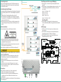
Einstellungen von Entzerrung und Dämpfung:
Mit den Jumpern (A) wird die Interstage-Entzerrung im Downstream
eingestellt.
Mit den Jumpern (B) wird eine Dämpfung im Upstream von bis zu 30dB
in 2 dB-Schritten eingestellt. Die Werte werden dazu von links nach
rechts addiert:
Jumper 1+2+3+4 unten = 0 dB
Jumper 1 oben = 2 dB
Jumper 2 oben = 4 dB
Jumper 1+2 oben = 6 dB
…
Jumper 1+2+3+4 oben = 30 dB
Einstellung BIAS:
Mit dem Jumper (C) wird eingestellt, ob der Upstream-Laser im
Continuous-Wave-Modus (CWM) oder im gepulsten Burst-Modus (BM)
arbeitet.
LED-Anzeigen:
9 Die LED Laser ON (D) leuchtet in grün, wenn der Upstream-Laser
eingeschaltet ist.
9 Die Status LED (E) leuchtet grün, wenn die optische Downstream-
Eingangsleistung im Bereich -8 dBm bis +1 dBm liegt.
9 Die Status LED (E) leuchtet rot, wenn die optische Downstream-
Eingangsleistung kleiner als -8 dBm ist.
A
B
C
D
E
1
2
2
3 45 6

Manufacturer
AXING AG
Gewerbehaus Moskau
8262 Ramsen
EEA contact address
Bechler GmbH
Am Rebberg 44
78239 Rielasingen
State of the art 2019-12-04
Technical improvements, changes in design, printing- and other errors expected.
Safety advices:
The device may only be installed and put into operation by personnel
who have received the necessary training on handling optical and
electrical devices and who have been instructed on safety instructions
for handling lasers.
Installation and repairs to the equipment may only be carried out by
technicians observing the current guidelines. No liability will be assumed
in the case of faulty installation and commissioning.
Before handling or opening the equipment pull out the power plug or
remove the power supply, otherwise there is danger of electrocution. This
is also valid for cleaning the equipment or working on the connections.
Only use the mains cable connected to the device. Never replace any
parts or make any modifications on the mains cable. Otherwise there is a
risk of mortal injury for which we cannot be held liable.
Providing that a serviceable fuse exists, the power cord must be pulled
out before changing the fuse. Defective fuses may only be replaced with
standard compliant fuses that have the same nominal value.
The equipment may only be operated in dry rooms. In humid rooms
or outdoors there is danger of short-circuit (caution: risk of fire) or
electrocution.
Choose a location of installation or mounting which complies to the
protection class IP 54.
Choose the location of installation or mounting so that the power plug
can be reached and pulled out of the socket easily in case of danger.
Choose the location of installation or mounting such that children may
not play unsupervised near the equipment and its connections. The
location of installation or mounting must allow a safe installation of all
cables connected. Power feeding cables as well as feeder lines may not
be damaged or clamped.
Avoid exposure of the equipment to direct sunlight and to other heat
sources (e. g. radiators, other electrical devices, chimneys, etc.).
Devices that are equipped with heat sinks or ventilation slots must under
no circum-stances be covered or blocked. Also ensure for a generous
air circulation around the equipment. In this way you avoid possible
damage to the equipment as well as a risk of fire caused by overheating.
Absolutely avoid that cables come near any source of heat (e.g.
radioators, other electrical devices, chimneys, etc.).
ONX 1550-01
premium-line
Micro Fibre Node
Operation instructions
Technical data:
Herewith AXING AG declares that the marked products comply with the valid
guidelines.
WEEE Nr. DE26869279 | Electrical and electronic components must not be
disposed of as residual waste, it must be disposed of separately.
Type ONX155001
Input
Optical connector 1 × SC/APC
Optical return loss ≥ 40 dB
Downstream
Wavelength 1540...1560 nm
Optical input level -8…+1 dBm
Optical OLC range 0…-6 dBm
Frequency range 85…1218 MHz
Output level @ OMI 3.5% (flat) 94 dBµV
CSO (Cenelec 42, OMI 3.5%) 60 dBc
CTB (Cenelec 42, OMI 3.5%) 60 dBc
Flatness ±1 dB
Noise current density 7,4 pA/√Hz
Equalization interstage: pluggable with jumpers 0/2/4/6 dB
Return loss ≥ 18 dB (-1,5 dB/octave)
Test port -20 dB
Upstream
Laser type DFB
Wavelength 1310 nm
Laser mode (switchable) CW/Burst
Optical output level +3 ±1 dBm
Laser switch-on time ≤ 1.3 µsec
RF level for laser on | off 67 dBµV | 58 dBµV
Frequency range 5…65 MHz
Flatness ±1 dB
Return loss ≥ 18 dB (-1,5 dB/octave)
Attenuation: adjustable in 2dB steps 0…30 dB
Test port -20 dB
RF connectors
Type F-female
General
Operation voltage 100...240 VAC
Power consumption 6 W
Operating temperature range 0...50 °C
Dimensions (W × H × D) appr. 195 x 90 x 55 mm

Field of application:
The devices are exclusively suitable for optical FTTH/FTTB applications or RFoG
networks! If the device is used for other applications, no guarantee is given!
Equipotential bonding and Mounting:
To avoid dangerous overvoltages (attention: risk of fire/death), the devices
must be connected to the equipotential bonding according to EN 60728-11.
Use the equipotential bonding connection of the device (1).
To connect the outer conductor of the coaxial cable to the equipotential
bonding, use e.g. earth connection blocks CFA or earthing angles QEW at
the output of the Micro Fibre Node.
Mount the device on a flat surface. Use the mounting screws included in
the delivery and the mounting holes of the devices (2).
Optical installation:
Laser radiation is invisible to the human eye.
Under no circumstances should you look inside the optical connectors
either with the naked eye and/or optical instruments! This can prove
seriously harmful to your health.
When performing work on the optical distribution network, make sure
that the lasers of the connected transmitter have been switched off by
disconnecting the mains plug.
The Micro Fibre Node has an optical SC-APC connector (3).
The overall input power must not exceed +2 dBm. Otherwise, the
photodiode may be damaged.
To protect the contact surfaces of the optical connectors the protectors should
be left in position until the connections are made.
Remove the protective cover from the connector without touching the
ferule.
Insert the connector following the guides until it clicks into place.
To remove the fibre, press the connector and pull out the cable.
RF installation:
The Micro Fibre Node has an F socket at the output (4).
Connect the output to your house distribution.
Use highly shielded coaxial cables with F connectors. Suitable cables and
connectors can be found at www.axing.com.
The Micro Fibre Node has one test port (F-female) each at the input (5) and at
the output (6).
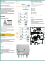
Adjustments of equalization and attenuation:
The jumpers (A) are used to set the interstage equalization in the
downstream.
The jumpers (B) are used to set an upstream attenuation of up to 30 dB
in 2 dB steps. The values are added from left to right:
Jumper 1+2+3+4 down = 0 dB
Jumper 1 top = 2 dB
Jumper 2 top = 4 dB
Jumper 1+2 top = 6 dB
…
Jumper 1+2+3+4 top = 30 dB
Adjustment of BIAS:
The jumper (C) controls whether the upstream laser operates in
continuous wave mode (CWM) or pulsed burst mode (BM).
LED indications:
9 The LED Laser ON (D) lights up green when the upstream laser is
switched on.
9 The Status LED (E) lights green when the optical downstream input
power is in the range -8 dBm to +1 dBm.
9 The Status LED (E) lights red when the optical downstream input power
is less than -8 dBm.
A
B
C
D
E
1
2
2
3 45 6
-
 1
1
-
 2
2
-
 3
3
-
 4
4


Axing premium-line ONX 1550-01 Operation Instructions
- Typ
- Operation Instructions
in anderen Sprachen
- English: Axing premium-line ONX 1550-01
Verwandte Artikel
-
Axing BVS 14-69 Operation Instructions
-
-
Axing premium-line Series Operation Instructions
-
-
Axing BVS 20-69 Operation Instructions
-
-
-
Axing BVS 13-68 CATV amplifier 30 dB Operation Instructions
-
-