
User Guide /
Bedienungsanleitung
GHV 12xx -85/-204
Series/Serie
Article Article no.
GHV 1230-85
GHV 1230-204
GHV 1240-85
GHV 1240-204
House Distribution
Amplifier
Hausanschlussverstärker
DOCSIS 3.1
323303
323313
323305
323315
Version 892289B Date 01/2019 EN/DE
DOCSIS 3.1
House Distribution Amplifier
Hausanschlussverstärker

GHV 1200-85/204 House Distribution Amplifier /
Hausanschlussverstärker
DOCSIS 3.1
1
EN/DE
Table of contents / Inhaltsverzeichnis
1.
GHV 1200 -85/-204 Series - Introduction (EN) ............................................................... 2
1.1
In the Box ................................................................................................................................. 2
1.2
Description............................................................................................................................... 2
1.3
Who should read this............................................................................................................... 2
1.4
Abbreviations and Symbols .................................................................................................... 2
1.5
Warranty .................................................................................................................................. 2
1.6
Security .................................................................................................................................... 2
1.7
Requirements and wrong handling ......................................................................................... 2
2.
Installation .................................................................................................................. 3
2.1
Safety precautions .................................................................................................................. 3
2.2
Local setup .............................................................................................................................. 3
2.3
Wall mounting.......................................................................................................................... 3
3.
Settings ....................................................................................................................... 4
3.1
Open amplifier & overview ...................................................................................................... 4
3.2
Adjustments & settings ........................................................................................................... 5
4.
Technical specifications ............................................................................................... 6
1.
GHV 1200 -85/-204 Serie – Einführung (DE) .................................................................. 7
1.1
Lieferumfang ........................................................................................................................... 7
1.2
Kurzbeschreibung ................................................................................................................... 7
1.3
Wer diesen Anleitung lessen sollte ........................................................................................ 7
1.4
Abkürzungen und Symbole ..................................................................................................... 7
1.5
Gewährleistung........................................................................................................................ 7
1.6
Sicherheitshinweise ................................................................................................................ 7
1.7
Bestimmungsgemäβe und sachwidrige Verwendung ........................................................... 7
2.
Montage ...................................................................................................................... 8
2.1
Sicherheitsanforderungen ...................................................................................................... 8
2.2
Örtliche Gegebenheiten........................................................................................................... 8
2.3
Wandbefestigung: ................................................................................................................... 8
3.
Einstellungen ............................................................................................................... 9
3.1
Anschluss- und Bedienelemente ............................................................................................ 9
3.2
Konfigurations- und Einstellungsmöglichkeiten .................................................................. 10
4.
Technische Daten ...................................................................................................... 11

GHV 1200-85/204 House Distribution Amplifier /
Hausanschlussverstärker
DOCSIS 3.1
EN/DE
2
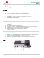
1. GHV 1200 -85/-204 Series - Introduction (EN)
1.1 In the Box
Amplifier with jumpers
User Guide
1.2 Description
The GHV 12xx series are Multimedia coaxial amplifiers for upgrading of smaller to medium sized CATV
networks to DOCSIS 3.1 operation in multi-dwellings. They are approved from by big cable operators in
Europe.
TRIAX is offering two different versions with upper frequencies 85Mhz or 204Mhz for the return path
All functional parts such as pre-amplifier, diplex filters, return channel amplifier and their operating and
setting components are fully integrated onto the circuit board. This allows a complete provisioning based
upon operational requirements without any additional parts like plug in modules or Pads.
Brand new 1.2 GHz MMIC technology for high output level
Readable setting of attenuation and equalization in 1dB steps
by using of reliable rotary switches and jumpers
Return path can be set for: ”active”, “passive” or ”off” (only GHV12xx -204)
Basic gain of the return path can be switched down by 6dB without any decreasing of
transmission performance
All connectors are reliable F-connectors, hand mounted.
Test ports bi-directional for input and uni-directional for output signal
Extensive ESD- and Surge-Protection
High efficient switching power supply with EU-plug, protection class II.
1.3 Who should read this 1.4 Abbreviations and Symbols
This User Guide is suitable for Technicians, Installers
and other Educated and Authorized Personnel who
Setup, Repair and Maintain Cable Network
Distribution Networks.
Bullet points
Actions
1.5 Warranty 1.6 Security
Please refer to your local sales representative for the
Warranty Terms of this product.
Unauthorized handling, installation and setup voids
any warranty claim.
Warning!
Non-compliance to the safety precautions for this
unit can cause Injuries, Death and can also damage
the unit..
1.7 Requirements and wrong handling
Only Technicians, Installers and other Educated and Authorized Personnel should Install, Setup, Repair and
maintain this unit under full compliance to the safety precautions.
Damage caused by unauthorized, wrong Installation or use, bad connections or other unauthorized handling
voids the Warranty.

GHV 1200-85/204 House Distribution Amplifier /
Hausanschlussverstärker
DOCSIS 3.1
3
EN/DE
2. Installation
2.1 Safety precautions
BEWARE:
You must adhere to the Safety Precautions of EN 60728-11 for installation
Before you start working on the installation, turn off Mains Power to the circuit.
Only let an authorized Electrician do the Mains power plug installation if needed.
Never do Installation or repair during thunder Storms.
Always connect the network by use of the Grounding Terminal of the device (with a copper wire
(diameter min. 4 mm2) to the Building Grounding Terminal!
Before you start working on the installation, turn off Mains Power to the circuit!
Observe the safety precautions!
2.2 Local setup
Mount the Amplifier.
Horizontal, free on the wall and so that the convection cooling of the unit
is not constrained.
On non-flammable material (Concrete or Brick Wall)
In a dust free environment, protected against moisture and fluid.
(Drop– and spray water)
Not in a spot with direct Sun radiation (e.g.. On the Roof)
Not directly along with Heat Sources (e.g. Heating Room)
In compliance with the highest allowed working Temperature
(measured at the Airflow under the Amplifier))
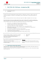
2.3 Wall mounting
Fasten the Amplifier according to its measurements (See Fig. 1.) on the wall.
(Screws-ø max. 4.8 mm, Distance between holes 158 mm)
Create a Grounding potential using the screw A and a sufficient fitted and stable copper cable
(diameter min. 4 mm2)
Connect the RF-Input B and the RF-Output C. Make sure you get perfect
connection between Coax cable and Connector.
Turn on the Mains Power to the circuit again.
Fig. 1
mounting

GHV 1200-85/204 House Distribution Amplifier /
Hausanschlussverstärker
DOCSIS 3.1
EN/DE
4
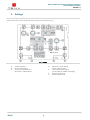
3. Settings
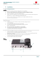
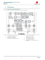
3.1 Open amplifier & overview
Remove the top cover of the Amplifier by removing screw D (see Fig. 1)
Fig 2 Inside
A. Setting elements
B. RF-Input, RP-Output
C. Test connector RF-Input /
RP-Output (bidirectional)
D. Connector for RP setting
(active, passive, OFF)
E. Test connector RF-Output
(uni-directional) -20dB HF-Ausgang
F.
RF-Output, RP-Input
G. Power ON/OFF LED

GHV 1200-85/204 House Distribution Amplifier /
Hausanschlussverstärker
DOCSIS 3.1
5
EN/DE
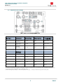
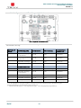
3.2 Adjustments & settings
Fig 3 Position of Jumpers/Setting elements
Provisioning of the amplifier using Rotary Switches and Jumpers as shown:
See Fig. 3 Downstream Setting Range Default setting
Setting element
Jumper fig.
1
Attenuator (Input)
In 1dB-Steps
0-15 dB 0 dB Rotary switch
2
Slope (Input)
in 1dB-Steps
0-15 dB 0 dB Rotary switch
3
Attenuator
(Interstage)
0 / 6 dB 0 dB Jumper
4 Slope (Interstage) 0 /3/7/10 0 dB Jumper
Upstream /
Return path
5 Basic gain reduction*
- 6 dB 0dB = max Gain Jumper
6
Attenuator (Input) *
in 1 dB-Steps
0/15 dB 0 dB Rotary switch
7 Slope (Interstage) 0 / 3 / 6 / 9 3 dB Jumper
8
Attenuator
(Interstage)*
0 / 6 dB 0 dB Jumper
9
Return Path
settings
Active / Passive /
OFF
Active Jumper
*) In order to remain the high signal to noise performance in the return path in most cases it’s recommended to do provisioning
of the return gain by setting elements in following order:
1. Reduce basic gain by 6dB (5) 2. Set interstage attenuator (8) 3. Set input attenuator (6) for the return path

GHV 1200-85/204 House Distribution Amplifier /
Hausanschlussverstärker
DOCSIS 3.1
EN/DE
6
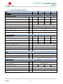
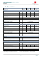
4. Technical specifications
Type
GHV 1230 -85 GHV 1230 -204 GHV 1240 -85 GHV 1240 -204
Article number
323303 323313 323305 323315
Forward path (downstream)
Frequency Range MHz 103…1218 258…1218 103…1218 258…1218
Max. Output level CENELEC raster, Slope 0/7 dB * dBµV 103 / 105 103 / 105 106 / 109 106 / 109
Max. Output level full digital load, Slope 0/7 dB ** 98 / 99 98 / 99 101 / 103 101 / 103
Gain dB 32 32 40 40
Attenuation, Interstage, Jumper dB 0 / 6
Attenuation, Input Rotary switch dB 0...15 (1dB-Steps)
Slope, Interstage, Jumper dB 0 / 3 / 7 / 10
Slope, Input Rotary switch dB 0...15 (1dB-Steps)
Noise Figure dB 6
Return path (upstream)
Frequency Range MHz 5…85 5…204 5…85 5…204
Max. Output level
@5 -85: 9 ch. 5-204: 24 ch, BER 1*10exp-9
dBµV 107 104 107 104
Upstream load (KDG 1TS 140) Class D Class D Class D Class D
Gain (switchable: max / max -6dB***) dB 26 / 20 26 / 20 32 / 26 32 / 26
Attenuation, Interstage, Jumper dB 0 / 6
Attenuation, Input Rotary switch dB 0...15 (1dB-Steps)
Slope, Interstage, Jumper dB 0 / 3 / 6 / 9
Noise Figure dB 5
General
Linearity dB ± 1
Return loss (@40MHz, -1.5dB/Octave) dB >18
Test connector (75Ω) Input/output/test F-female / -20dB (Bi- / Uni-directional)
Operating conditions
Diameters W x H x D mm 169 x 76 x 65
Input supply voltage V~/Hz
190—264 / 50...60
Power Consumption (typ.) W 6.8 6.8 11.0 11.0
ESD / Surge protection / Safey / protection kV 10 / 1 / Class II / IP 20
Operating temperature °C -25…+55
Weight g 750
*) CTB/CSO 60dBc
@
41ch 103…862MHz; 31ch 256…862MHz:. **) [email protected] 138x256QAM, 256…1218MHz :119x256QAM
***) Switching of gain in first stage by using a jumper

GHV 1200-85/204 House Distribution Amplifier /
Hausanschlussverstärker
DOCSIS 3.1
7
EN/DE
1. GHV 1200 -85/-204 Serie – Einführung (DE)
1.1 Lieferumfang
Verstärker mit Netzteil und allen Einstellelementen
Bedienungsanleitung
1.2 Kurzbeschreibung
Die multimediafähigen Hausanschlussverstärker der GHV 12xx Serie sind für die Aufrüstung von
Kabelfernsehverteilanlagen auf DOCSIS 3.1 Betrieb in kleineren bis mittelgroßen Wohngebäuden konzipiert.
Sie werden zum Ausgleich der Kabel– und Verteildämpfung im BK-Hausnetz eingesetzt.
Die TRIAX Verstärker gibt es in zwei Versionen: mit oberer Rückweggrenzfrequenz 85Mhz oder 204Mhz.
Die Hausanschlussverstärker der GHV 12xx-Famile haben alle wichtigen Funktionseinheiten wie
Vorwärtsverstärker, Diplexfilter, Rückwegverstärker und die zugehörigen Stellglieder und Drehschalter
vollständig auf der Leiterplatte implementiert. So werden keine weiteren Zubehörteile wie Module oder
Steckelemente für die Inbetriebnahme oder den Betrieb benötigt, um die Geräte vor Ort zu konfigurieren..
Modernste 1.2 GHz MMIC Technologie für hohe Aussteuerfähigkeit
Dämpfung und Leitungsentzerrung mittels zuverlässigen und ablesbaren Drehschaltern in 1dB-
Stufen einstellbar. Grundverstärkungen mit Jumpern wählbar
Rückweg schaltbar: Aktiv / Passive / Aus
Rückwegverstärkung kann in der Vorstufe um 6dB verringert werden, ohne die
Verstärkungsperformance hinsichtlich Rauschen und Aussteuerfähigkeit zu verschlechtern
Alle HF-Anschlüsse sind handmontierte, hochwertige F-Buchsen
Testbuchse bidirektional am Eingang und unidirektional am Ausgang des Verstärkers
Extensiver ESD– und Surge-Schutz
Niedriger Energiebedarf durch hocheffizientes Schaltnetzteil mit Schutzklasse II Euro-Netzstecker
1.3 Wer diesen Anleitung lessen sollte 1.4 Abkürzungen und Symbole
Diese Anleitung richtet sich an Techniker,
Installateure oder eingewiesene Personen, die
Antennenanlagen in Betrieb nehmen, warten oder
betreuen.
Aufzählung
Handlungsschritt
1.5 Gewährleistung 1.6 Sicherheitshinweise
Die gesetzliche Gewährleistung nach Paragraph 437
BGB beträgt 24 monate. Bei unsachgemäβer
Installation und Handhabung erlischt jeglicher
Garantieanspruch.
Warnung!
Die Nichtbeachtung der gegebenen
Vorsichtsmaβnahmen kann zu Personen
Oder Sachbeschädigungen führen.
1.7 Bestimmungsgemäβe und sachwidrige Verwendung
Die Montage und Inbetriebnahme darf nur von eingewiesenen Personen, Technikern oder
Installateuren unter Beachtung der Sicherheitsbestimmungen durchgeführt werden.
Schäden durch falsche Montage und Inbetriebnahme, fehlerhafte Steckverbindungen an Kabeln
oder sonstige unsachgemäβe Handhabung führen zum Erlöschen des Garantieanspruchs.

GHV 1200-85/204 House Distribution Amplifier /
Hausanschlussverstärker
DOCSIS 3.1
EN/DE
8
2. Montage
2.1 Sicherheitsanforderungen
ACHTUNG:
Die Sicherheitsanforderungen nach EN 60728-11 sind unbedingt zu beachten.
Lassen Sie einen evtl. notwendigen 230 VAC Netzanschluss grundsätzlich vom
Fachmann anbringen.
Führen Sie Installationen oder Servicearbeiten nie bei Gewitter durch.
Binden Sie das Gerät an der Potentialausgleichschraube über eine gelb-grün ummantelte Cu-
Leitung mit Querschnitt min. 4 mm2 an die Potentialausgleichsschiene der Hausanlage an.
Schalten Sie vor Arbeiten an elektrischen Anlagen immer den Stromkreis ab!
Beachen Sie die Sicherheitshinweise!
2.2 Örtliche Gegebenheiten
Montieren Sie den Verstärker.
Waagerecht, frei an der Wand und so, dass die Konvektionskühlung des Verstärkers nicht
behindert wird
Auf schwer entflammbarem Untergrund (Mauer)
In staubfreier Umgebung, geschützt gegen Feuchtigkeit und Nässe (Tropf– und Spritzwasser)
Nicht an einen Ort mit direkter Sonneneinstrahlung (z.B. Dachboden)
Nicht in unmittelbarer Nähe von Wärmequellen (z.B. Heizraum)
Unter Berücksichtigung der maximal zulässigen Betriebstemperatur (gemessen am Luftstrom
unter dem Verstärker)
2.3 Wandbefestigung:
Schrauben Sie den Verstärker gemäβ Bemaβung (siehe Abb. 1) an die Wand (Schrauben-ø max.
4.8 mm, Abstand der Bohrungen 158 mm)
Stellen Sie einen Potentialausgleich an der Potentialausgleichschraube A des Gehäuses mittels
eines mechanisch stabilen Schutzleiters her (Querschnitt min. 4 mm2)
Schlieβen Sie den HF-Eingang B und den HF-Ausgang C an. Achten Sie auf einwandfreie
Steckverbindungen an den Kabeln.
Abb. 1

GHV 1200-85/204 House Distribution Amplifier /
Hausanschlussverstärker
DOCSIS 3.1
9
EN/DE
3. Einstellungen
3.1 Anschluss- und Bedienelemente
Entfernen Sie den Gehäusedeckel mittels Zentralschraube D (siehe Abb. 1)
Abb 2 Innenansicht
A. Einstellelemente/Drehschalter
B. HF-Eingang, RK-Ausgang
C. Messbuchse HF-Eingang /
RK-Ausgang (bidirektional) -20dB
D. Stecker für RK einstellung
(active, passive, OFF)
E. Messbuchse HF-Ausgang
(uni-direktional) -20dB
F. HF-Ausgang, RK-Eingang
G. Leuchtdiode: Versorgungsspannung
Ein/Aus

GHV 1200-85/204 House Distribution Amplifier /
Hausanschlussverstärker
DOCSIS 3.1
EN/DE
10
3.2 Konfigurations- und Einstellungsmöglichkeiten
Abb 3 Lage der Einstellelemente
Das Konfigurieren und Einstellen des Verstärker erfolgt durch Umstecken von Steckbrücken sowie mittels
Drehschaltern wie folgt:
Element auf
Abb. 3
Vorwärtsweg (VW) Einstellbereich Voreinstellung
Einstellelement
Brücken, Abb.
1
Pegelsteller (Eingang)
In 1dB-Schritten
0-15 dB 0 dB Drehschalter
2
Entzerrung (Eingang)
in 1dB-Schritten
0-15 dB 0 dB Drehschalter
3 Pegelsteller (Interstage) 0 / 6 dB 0 dB Steckbrücke
4 Entzerrung (Interstage) 0 /3/7/10 0 dB Steckbrücke
Rückwärtsweg (RW)
5 Grundverstärkung* - 6 dB Max Verstärkung Steckbrücke
6
Pegelsteller (Eingang)*
in 1 dB-Schritten
0/15 dB 0 dB Drehschalter
7 Entzerrer (Interstage) 0 / 3 / 6 / 9 3 dB Steckbrücke
8 Pegelsteller (Interstage)* 0 / 6 dB 0 dB Steckbrücke
9 Rückwegbetrieb Aktiv/ Passiv / Aus Aktiv Steckbrücke
*) Um die Signalgüte so wenig wie möglich zu verringern, wird im Normalfall empfohlen, die Reduzierung der
Rückwegverstärkung in folgender Reihenfolge vorzunehmen:
1. -6dB Grundverstärkung (5) 2. Interstage Dämpfung (8) 3. RW- Eingangsdämpfungssteller (6)

GHV 1200-85/204 House Distribution Amplifier /
Hausanschlussverstärker
DOCSIS 3.1
11
EN/DE
4. Technische Daten
Typ
GHV 1230 -85
GHV 1230 -204
GHV 1240 -85
GHV 1240 -204
Artikelnummer 323303 323313 323305 323315
Vorwärtsweg
Frequenzbereich MHz 103…1218 258…1218 103…1218 258…1218
Max. Ausgangspegel CENELC Raster*, Slope 0/7 dB dBµV 103 / 105 103 / 105 106 / 109 106 / 109
Max. Ausgangspegel digitalelLast**, Slope 0/7 dB 98 / 99 98 / 99 101 / 103 101 / 103
Verstärkung dB 32 32 40 40
Dämpfung Interstage, schaltbar dB 0 / 6
Dämpfungsteller am Eingang dB 0...15 (1dB-Schritte)
Entzerrung Interstage, schaltbar dB 0 / 3 / 7 / 10
Entzerrungssteller am Eingang dB 0...15 (1dB-Schritte)
Rauschmaβ dB 7
Rückwärtsweg
Frequenzbereich MHz 5…85 5…204 5…85 5…204
Max. Ausgangspegel
@5 -85: 9 ch. 5-204: 24 ch, BER
1*10exp-9
dBµV 107 104 107 104
Kanal last (KDG 1TS 140) Klasse D Klasse D Klasse D Klasse D
Verstärkung (max / max -6dB*** ) dB 26 / 20 26 / 20 32 / 26 32 / 36
Dämpfung Interstage, schaltbar dB
0 / 6
Dämpfungssteller am Eingang dB 0...15 (1dB-Schritte)
Entzerrung Interstage, schaltbar dB 0 / 3 / 6 / 9
Rauschmaβ dB 5
Allgemeines
Linearität Amplitudenfrequenzgang dB ± 1
Rückflussdämpfung (@40MHz, -1.5dB/Oktave) dB >18
HF-Anschlüsse (75Ω) Eingang/Ausgang/ Test F-Buchse / Bi- / Uni-direktional -20dB
Betriebsbedingungen
Abmessungen B x H x T mm 169 x 76 x 65
Versorgungsspannung V~/Hz 190—264 / 50...60
Power Leistungsaufnahme (typ.) W 6.8 6.8 11.0 11.0
ESD / Surge – Schutz / Schutzart / Schutzklasse kV 10 / 1 / Class II / IP 20
Betriebstemperaturbereich °C -25…+55
Gewicht g 750
*) CTB/CSO 60dBc
@
41ch 103…862MHz; 31ch 256…862MHz:. **) [email protected] 138x256QAM, 256…1218MHz :119x256QAM
***) Umschaltung der Vorstufenverstärker mittels Brücke.

Notes-Notizen-Notes-Notas-Notater

This page is intentionally left blank !
Diese Seite ist mit Absicht leer !
Cette page a été laissée blanche intentionnellement !
Esta página se ha dejado en blanco intencionalmente !
Denne side er med vilje efterladt tom

This page is intentionally left blank !
Diese Seite ist mit Absicht leer !
Cette page a été laissée blanche intentionnellement !
Esta página se ha dejado en blanco intencionalmente !
Denne side er med vilje efterladt tom

triax.com
triax.dk - triax.se - triax-gmbh.de - triax.fr -
triaxmultimedia.es - triax.uk
triax.at – triax.hu
Information and manuals
:
Information og brugervejledninger:
Information och manualer:
Information und Bedienungsanleitungen:
Informations et modes d’emploi:
Información y manuales:
Lisätietoja ja oppaita:
információk és útmutatók:
Copyright © 2018 TRIAX. All rights reserved.
The TRIAX Logo and TRIAX Multimedia are registered trademark(s) of the
TRIAX Company or its affiliates.
TRIAX A/S | Bjørnkærvej 3 | 8783 Hornsyld | Denmark
Subject to change without notice
Änderungen vorbehalten
Peut être sujet à modification sans préavis
-
 1
1
-
 2
2
-
 3
3
-
 4
4
-
 5
5
-
 6
6
-
 7
7
-
 8
8
-
 9
9
-
 10
10
-
 11
11
-
 12
12
-
 13
13
-
 14
14
-
 15
15
-
 16
16


Triax GHV 1230-85 Benutzerhandbuch
- Typ
- Benutzerhandbuch
- Dieses Handbuch eignet sich auch für
in anderen Sprachen
- English: Triax GHV 1230-85 User manual
Verwandte Artikel
Andere Dokumente
-
GSS AR 5301 Assembly Instructions Manual
-
Axing BVS 14-69 Operation Instructions
-
Kathrein VOS 22/RA Schnellstartanleitung
-
-
-
-
POLYTRON HV 40 Distribution amplifier 40 dB Bedienungsanleitung
-
POLYTRON HV 18 Distribution amplifier 18 dB Bedienungsanleitung
-
LevelOne POR-1222 Installationsanleitung
-