
Absolut-ENCODER AE1
Variante M-BUS / SCR
Ausgabe: 02.2010
Montageanleitung
z Bitte lesen und aufbewahren
Zeichenerklärung
z, 1., 2., 3, = Tätigkeit
→ = Hinweis
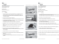
Plombe entfernen. Linsenschraube M3x10 in der Kappe mit Kreuz-1.
schlitz-Schraubendreher (Größe PH 1 herausschrauben (Abb. 1).
Die Plombe kann mit einem Schlitz-Schraubendreher durchstochen →
und entfernt werden.
Kappe des Klemmenmoduls entfernen.2.
Zur leichteren Montage kann das Klemmenmodul abgezogen werden. →
Vorkonfektioniertes Kabel (z. B. JY (ST) Y 2x2x0,6) in Zugentlastung 3.
des Klemmenmoduls einführen (Abb. 2).
Zugentlastung ist über Führung des Kabels gewährleistet. →
Kabelenden unter den Schraubklemmen positionieren und festklem-4.
men.
Die Anschlüsse sind frei wählbar, unabhängig von der Polarität →
(Abb. 3).
Optional 2-adriges Kabel mit Kabelbinder fi xieren (Abb. 3). 5.
Klemmenmodul auf den Zählwerkrahmen aufstecken. 6.
Dabei ist darauf zu achten, dass die Kontakte des 4-poligen Steckers →
nicht verbiegen.
Kappe aufsetzen und mit Linsenschraube befestigen.7.
Klemmenmodul und Deckel werden mit der Plombierhülse plombiert. 8.
(Abb. 4).
Testauslesung vornehmen. 9.
Zählwerke mit SCR-Schnittstelle unterstützen das OBIS Kennzahlen- →
system.
Absolute ENCODER AE1
Variation M-BUS / SCR
Issue: 02.2010
Assembly Instruction
z Please read and keep in a safe place
Explanation of symbols
z, 1., 2., 3, = Action
→ = Instruction
Remove the plastic seal. Unfi x the lens head screw M3x10 in the cap 1.
with phillips tipp screwdriver size PH 1 (fi gure 1).
The plastic seal can be pierced and removed with a slit screwdriver. →
Remove the cap of the clamp-module.2.
For the easier assembly the module can be removed. →
Pass a prepared wire (e. g. JY(ST)Y2x2x0,6) through the strain relief 3.
of the clamp module (fi gure 2).
The strain relief is warranted by the conducted wire. →
Place and buckle the cable claims under the pinch screw.4.
Connections are free eligible, independent of the polarity (fi gure 3). →
The cable can optionally be fi xed with a cable fastener (fi gure 3). 5.
Put the clamp-module on the index frame. 6.
Take care that the four contacts of the plug don´t bend. →
Put the cap on the clamp-module and fi x it with the lens head screw.7.
Clamp-module and cap are sealed with the plastic seal. (fi gure 4).8.
Carry out a test read.9.
Indexes with SCR-Interface provide the OBIS identifi cation numbers. →
Elster GmbH, Steinern Str. 19 – 21, 55252 Mainz-Kastel
D GB
Abbildung 1 Figure
Abbildung 4 Figure
Abbildung 3 Figure
Abbildung 2 Figure
Technische Änderungen vorbehalten Alle Rechte vorbehalten Subject to change with prior notice All rights reserved
-
 1
1
