Elster BK-G40(T), BK-G65(T), BK-G100(T) Bedienungsanleitung
- Typ
- Bedienungsanleitung

Instruction Manual
Industrial Diaphragm Gas Meters
Betriebsanleitung
Industrie-Balgengaszähler
Mode d’emploi
Computeurs de gaz à membranes
Instruzioni d’uso
Contatori gas a pareti deformabili per uso industriale
Návod k obsluze
Prumyslový membránový plynomer
Návod na obsluhu
Priemyselný membránový plynomer
Bedieningsvoorschrift
Industrie Balgengasmeters
Type BK-G40 · BK-G65 · BK-G100 and
Type BK-G40T · BK-G65T · BK-G100T
Typ BK-G40 · BK-G65 · BK-G100 und
Typ BK-G40T · BK-G65T · BK-G100T
Types BK-G40 · BK-G65 · BK-G100 et
Types BK-G40T · BK-G65T · BK-G100T
Tipo BK-G40 · BK-G65 · BK-G100 e
Tipo BK-G40T · BK-G65T · BK-G100T
Typ BK-G40 · BK-G65 · BK-G100 a
Typ BK-G40T · BK-G65T · BK-G100T
Typ BK-G40 · BK-G65 · BK-G100 a
Typ BK-G40T · BK-G65T · BK-G100T
Type BK-G40 · BK-G65 · BK-G100
Type BK-G40T · BK-G65T · BK-G100T
Manual de instrucciones
Contadores industriales de gas de membranas
Tipo BK-G40 · BK-G65 · BK-G100 y
tipo BK-G40T · BK-G65T · BK-G100T
˚ ˇ


EnglishDeutschFrançaisItaliano
CeštinaSlovencina
Nederlands
Instruction Manual
Industrial Diaphragm Gas Meters
Betriebsanleitung
Industrie-Balgengaszähler
Mode d’emploi
Computeurs de gaz à membranes
Instruzioni d’uso
Contatori gas a pareti deformabili per uso industriale
Návod k obsluze
Průmyslový membránový plynoměr
Návod na obsluhu
Priemyselný membránový plynomer
Bedieningsvoorschrift
Industrie Balgengasmeters
Type BK-G40 · BK-G65 · BK-G100 and
Type BK-G40T · BK-G65T · BK-G100T
Typ BK-G40 · BK-G65 · BK-G100 und
Typ BK-G40T · BK-G65T · BK-G100T
Types BK-G40 · BK-G65 · BK-G100 et
Types BK-G40T · BK-G65T · BK-G100T
Tipo BK-G40 · BK-G65 · BK-G100 e
Tipo BK-G40T · BK-G65T · BK-G100T
Typ BK-G40 · BK-G65 · BK-G100 a
Typ BK-G40T · BK-G65T · BK-G100T
Typ BK-G40 · BK-G65 · BK-G100 a
Typ BK-G40T · BK-G65T · BK-G100T
Type BK-G40 · BK-G65 · BK-G100
Type BK-G40T · BK-G65T · BK-G100T
Espanol
Manual de instrucciones
Contadores industriales de gas de membranas
Tipo BK-G40 · BK-G65 · BK-G100 y
tipo BK-G40T · BK-G65T · BK-G100T
ˇˇ
̃


Instruction Manual
Industrial Diaphragm Gas Meters
Type BK-G40 · BK-G65 · BK-G100 and
Type BK-G40T · BK-G65T · BK-G100T
English

Elster GmbH
4 © Elster GmbH · All rights reserved · Subject to technical modication
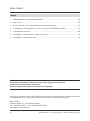
Contents
1. Intended Use and Field of Application ................................................................................ 05
2. Technical Data .................................................................................................................... 06
3. Pressure and Temperature Test Points ............................................................................... 7
4. Index / Index with Check Digit Facility / Absolute ENCODER ............................................. 7
5. Pulse Generator ................................................................................................................. 08
6. Installation / Connection / Commissioning ......................................................................... 9
7. Recycling and Environmental Protection ............................................................................ 11
Important:
Read and note the operating instructions and
safety information before installing or commissioning!
Always pass them on to the operator.
Please contact your Elster-Instromet Customer Service for assistance in commissioning or in-
stallation of encoders, pulse generators and volume correctors for instance.
Elster GmbH
Steinern Straße 19 · 55252 Mainz-Kastel
Tel. +49 (0)6134/605-0 · Fax +49 (0)6134/605-390
www.elster-instromet.com

Elster GmbH
© Elster GmbH · All rights reserved · Subject to technical modication 5
1. Intended Use and Field of Application
This product is intended to be used
for the scal volumetric metering of
– ammable gases: natural gas / town gas / propane / butane,
– non-ammable gases: air / nitrogen / inert gases,
– inert gases pursuant to DVGW Code of Practice G260.
This product is not intended
– for metering of aggressive gases, e.g. biologically produced methane or sewage gases,
oxygen, acetylene.
The permitted operating / ambient temperature is tm = -25°C to +55°C, unless otherwise speci ed
on the main plate (index plate).
For meters on which conformity with Directive 2004/22/EC (MID) is declared on the main plate,
the following speci cations also apply:
The gas temperature where the measurement error still lies within the error limits as set out in the
Directive is t = 10°C to +40°C, unless otherwise specied on the main plate.
g
The meters are suitable for mechanical ambient conditions of Class M1 of the Directive. For
meters with an encoder index, Class E2 for electromagnetic ambient conditions also applies.
Conformity with Directive 2004/22/EC is declared by af xing the following marking:
on which the 2-digit year of the Declaration of Conformity (year of construction) is to be inserted
after the letter “M”.
Elster’s industrial diaphragm gas meters are always to be transported and stored in the upright
position.
The permitted storage temperature is -25°C to +60°C.
M .. 0102
English
ATEX identication
– Use as follows:
Ex
II
2
G
Ex h
IIC
T4
Gb
Marking of explosion protection
Equipment group:industrial (mining excluded)
Equipment category 2 (Zone 1)
Potentially explosive gas atmospheres
Type of ignition protection: mechanical explosion protection
Explosion group for gases
Temperature class
Equipment protection level

Elster GmbH
6
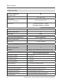
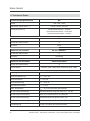
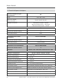
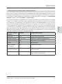
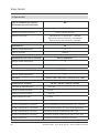
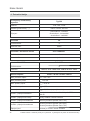
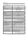
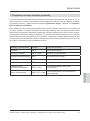
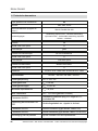
2. Technical Data
Industrial diaphragm
gas meter type
BK
Size G40, G65, G100
Nominal size
(pursuant to standard...)
DN 65, DN 80, DN 100
Pipe layout Co-axial connection – vertical
Two-pipe connection – horizontal
Two-pipe connection – vertical
Index Z6
Number of digit rollers 8
Check digit None
Index with check digit facility ®
Z6 with CHEKKER
Number of digit rollers 8
Check digit Two-digit notation
Index with ENCODER Absolute ENCODER
Number of digit rollers 8
Interfaces
Pulse generators IN-Z61/IN-Z62/IN-Z63/IN-Z64
Connection voltage U = 24 V DC
max
Connection current I = 50 mA
max
Connection rating P = 0.25 W
max
Min. pulse duration T = 0.25 s
min
Max. resistance R = 0.5 Ohm (contact closed)
max
IN-Z61 plug connection Standard modular plug 6/4 pursuant to FCC, Part 68
IN-Z62 terminal connection Cable and luster terminals in housing
IN-Z63 plug connection Circular plug (Binder series 723)
IN-Z64 plug connection Circular plug (Binder series 723 and 423)
Pin assignment Printed on the front of the pulse sensor
M-BUS, SCR- OBIS 2005, M-BUS & SCR- OMS
© Elster GmbH · All rights reserved · Subject to technical modication

7
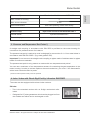
Thermowell*) Standard welded thermowell EBL 100
Max. number in housing 2
Max. sensor diameter 6 mm
Sensor attachment Soft cable pressing; strain relief facility
Pressure tap*) Pipe screw unions to DIN 2353/ISO 8434-1
Internal thread Cylindrical thread M10x1
Connection pipe
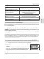
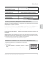
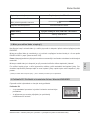
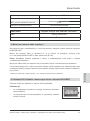
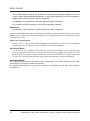
3. Pressure and Temperature Test Points*)
A straight male coupling in accordance with DIN 2353 is pre-tted on the meter housing for
connection of a pressure sensor for instance.
The pressure test point is marked pm and is designed for connection of d = 6 mm steel tubes in
accordance with DIN EN 10305-1 (e.g. steel grade E 235).
Important: Do not connect the straight male coupling to pipes made of stainless steel or pipes
made of nonferrous materials.
The pressure test point is only present on meters with two temperature test points!
You can use a maximum of two temperature sensors for measuring the gas temperature in the
meter housing. In order to achieve optimum thermal conduction, you must ll the thermowells
with a heat-conductive uid or paste.
*) Pressure and temperature test points are optional!
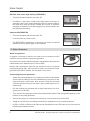
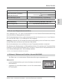
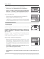
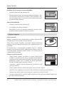
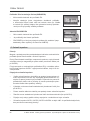
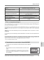
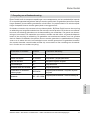
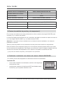
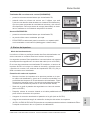
4. Index / Index with Check Digit Facility / Absolute ENCODER
The meter can be equipped with various index versions:
Z6 index
– This is the standard version with an 8-digit mechanical roller
index.
– Designed for LF pulse generators which can be plugged on from
the outside and which can be exchanged on site.
Elster GmbH
© Elster GmbH · All rights reserved · Subject to technical modication
6 mm
English

Elster GmbH
8
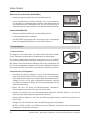
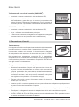
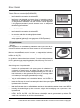
®
Z6 index with check digit facility (CHEKKER )
– This has the same features as index Z6.
– In addition, it also has a 2-digit check digit, which is set up in a
particular ratio to the meter reading and which checks whether
the read value and the device number are correct. A software
package is installed in the data logging unit, which enables the
test process (decoding).
Absolute ENCODER Z6
– This has the same features as index Z6.
– It can be used as a main index.
– The ENCODER is suitable for connection to a series-connected
additional device (data logger or bus system).
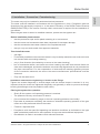
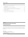
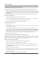
5. Pulse Generator
Mode of operation:
A magnet in the last or last but one roller of the mechanical index
switches a reed contact in the pulse generator.
A second reed contact allows magnetic manipulation attempts and
cable breaks to be detected (not in the IN-Z62).
Meters with mechanical index Z6 are delivered with an enclosed
pulse generator IN-Z61, with connection cable, rivet and seal. Pulse
generators IN-Z62/63 and 64 are mounted on the index.
Connecting the pulse generator:
– Attach the pulse generator in the opening located on the bottom
of the meter and swing it into the sealable plug connector on the
right-hand side of the meter. Now secure it with the enclosed
rivet and seal (for this you will need a pair of sealing pliers or a
similar tool).
– Pull the locking pin provided with a snap mechanism out of its
guide (only for IN-Z61).
– Then connect the plug at the end of the prefabricated cable in the designated opening on the
bottom of the pulse generator.
– Secure the plug by re-inserting the locking pin into its guide (only for IN-Z61).
– Assign the terminals in accordance with the pin assignment on the pulse generator.
– IN-Z61, IN-Z62, IN-Z63 and IN-Z64 can be retrof i tted onto the Z6 index at any time without
breaking the calibration seal.
© Elster GmbH · All rights reserved · Subject to technical modication

9
6. Installation / Connection / Commissioning
The meter may only be installed by authorized trained personnel.
The meter must be installed in accordance with the regulations in force. Compliance with the
directives of the gas supply company or, in the case of Germany, of the DVGW Code of Practice
G600 (DVGW-TRGI), in the version currently valid in each case, is required for the installation of
gas meters.
Before installation please ensure:
– that the protective caps and/or plastic sheeting is or are removed,
– that the meter and accessories have been inspected for transport damage,
– that the accessories have been checked for completeness and
– that you only use seals made from approved materials.
Then install the meter
– gas-tight,
– in the driest possible environment and where it may be easily read (the meter must not come
into contact with surrounding masonry),
– only in ow direction (as marked by an arrow on the meter housing),
– free of mechanical stress, and make sure when inserting the seals that the seal faces are
clean and undamaged, and that the seals are concentrically aligned and do not protrude into
the pipe cross-section. For the compression of seals and the resulting tightening torques
for the connection elements, the seal or the screw manufacturers’ speci cations must be
observed.
– Only use the seals once!
Placing the system into operation
– Slowly fi ll the system until operating pressure is reached.
– The pressure rise may not exceed 15 mbar/s.
– Do not exceed the measuring range or the max. operating pressure even brie y!
– Pipe tests at pressures exceeding the maximum allowable operating pressure of the gas
meter are to be performed without the meter.
– Conduct a tightness test!
– Compliance with the speci ed operating and ambient conditions as indicated on the type
label is absolutely essential for safe operation of the meter and additional equipment.
– Recalibration is made in accordance with national Directives.
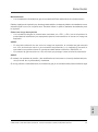
Installation instruction for tightening of screws at the
flange:
Tighten the screws diagonally in several stages until the desired torque is reached. It is very
important that the screws are tightened diagonally and gradually in order to prevent the ange
bending (both anges must be parallel to each other).
Elster GmbH
© Elster GmbH · All rights reserved · Subject to technical modication
When the gas meter is stored or installed outdoors, protect the site against rain.
English

Elster GmbH
10 © Elster GmbH · All rights reserved · Subject to technical modication
Maintenance:
– Elster industrial diaphragm gas meters are maintenance-free.
WARNING:
Improper installation, pressure tests, modi cations or incorrect use can cause personal injury or
damage to property.
If the seal has been damaged or removed, the gas meter is no longer approved for scal
measurements.
The plastic cover of the index must never be cleaned with a dry cloth owing to the risk of explosion
resulting from electrostatic discharge! An adequately moistened cloth can be used for cleaning.
Potentially explosive atmosphere
– Diaphragm gas meters that are labelled with <CE> and <Ex> (see sticker near the index) are
suitable for operation in potentially explosive atmospheres.
WARNING:
– The gas meter marked with <Ex> must be included in the equipotential bond when being
installed in a potentially explosive atmosphere, e.g. by connecting it to a grounded pipeline.
Installation must be carried out in accordance with EN 60079-14.
– The gas meter marked with <Ex> must be protected from falling parts.

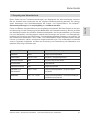
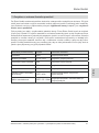
7. Recycling and Environmental Protection
Elster GmbH has reduced the transport packagings of its measuring instruments to the bare
essentials. Packaging materials are always selected consistently with a view to recycling. The
cardboard items used constitute secondary raw materials for the paperboard and paper indus-
®
try. The Instapak foam packaging items are recyclable and can be reused.
Plastic sheeting and strips/bands are also made of recyclable plastic. At Elster GmbH, subse-
quent recycling and disposal are already elements of the product development process. When
selecting the materials, we allow for reusability of the materials, suitability of materials and sub-
assemblies for dismantling and separation, and the risks of environmental pollution and health
risks when recycling and dumping on land ll sites. The industrial diaphragm gas meters mainly
consist of metallic materials which can be melted down again in steelworks and metallurgical
plants and which can thus be reused a virtually unlimited number of times. The plastics used
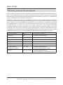
are listed below so that sorting and separating of the materials for the purposes of subsequent
recycling is possible.
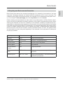
Plastic parts Abbreviation Chemical name
Counter PBTP Polybutylenterephthalat
Digit rollers PA 12 / PPO Polyamid / Polyphenylenoxyd
Counter cover ASA Acrylnitril-Styrol-Acrylester
Viewing glass PC Polycarbonat
Counter buttom
section
PPE Polyphenylenether
Gears and small
parts
PBTP / ASA Polybutylenterephthalat / Acrylnitril-Styrol-
Acrylester
Measuring unit PBT / PF / POM Polybutylenterephthalat / Phenolformaldehyd /
Acetalhomopolymerisat
11
Elster GmbH
© Elster GmbH · All rights reserved · Subject to technical modication
English


Betriebsanleitung
Industrie-Balgengaszähler
Type BK-G40 · BK-G65 · BK-G100 und
Type BK-G40T · BK-G65T · BK-G100T
Deutsch

Elster GmbH
14 © Elster GmbH · Alle Rechte vorbehalten · Technische Änderungen vorbehalten
Inhalt
1. Verwendungszweck und Anwendungsbereich .................................................................... 15
2. Technische Daten ................................................................................................................ 16
3. Druck- und Temperaturmessstellen ..................................................................................... 17
4. Zählwerk / Zählwerk mit Prüfziffer / Absolut ENCODER ...................................................... 17
5. Impulsgeber ........................................................................................................................ 18
6. Montage / Anschluss / Inbetriebnahme ............................................................................... 19
7. Recycling und Umweltschutz .............................................................................................. 21
Achtung:
Vor Einbau und Inbetriebnahme die Betriebsanleitung und
Sicherheitshinweise lesen und beachten!
Immer dem Betreiber übergeben.
Zur Unterstützung bei Inbetriebnahme oder Installation von z. B. Encodern, Impulsgebern oder
Mengenumwertern steht Ihnen der Elster-Instromet-Kundendienst gerne zur Verfügung.
Elster GmbH
Steinern Straße 19 · 55252 Mainz-Kastel
Tel. +49 (0)6134/605-0 · Fax +49 (0)6134/605-390
www.elster-instromet.com

Elster GmbH
© Elster GmbH · Alle Rechte vorbehalten · Technische Änderungen vorbehalten 15
1. Verwendungszweck und Anwendungsbereich
Dieses Produkt ist vorgesehen
zur eichfähigen Volumenmessung von
– brennbaren Gasen: Erdgas / Stadtgas / Propan / Butan
– nicht brennbaren Gasen: Luft / Stickstoff / Edelgasen
– inerten Gasen nach DVGW-Arbeitsblatt G260
Dieses Produkt ist nicht vorgesehen
– für die Messung von aggressiven Gasen, z. B. Bio- oder Klärgasen, Sauerstoff, Acetylen.
Die zulässige Betriebs- / Umgebungstemperatur beträgt tm = -25 °C bis +55 °C, wenn auf dem
Hauptschild (Zifferblatt) nicht anders angegeben.
Für Zähler, bei denen auf dem Hauptschild die Konformität mit der Richtlinie 2004/22/EG (MID)
erklärt wird, gelten darüber hinaus noch folgende Angaben:
Die Gastemperatur, bei der der Messfehler noch innerhalb der geforderten Fehlergrenzen der
Richtlinie liegt, beträgt tg = -10 °C bis +40 °C, sofern auf dem Hauptschild nicht anders ange-
geben.
Die Zähler sind geeignet für mechanische Umgebungsbedingungen der Klasse M1 der Richtli-
nie. Für Zähler mit Encoder-Zählwerk gilt zusätzlich die Klasse E2 für elektromagnetische Um-
gebungsbedingungen.
Die Konformität der Richtlinie 2004/22/EG wird durch die Kennzeichnung mit nachfolgendem
Zeichen erklärt:
wobei hinter dem M die zweistellige Jahreszahl der Konformitätserklärung (Baujahr) eingefügt wird.
Elster-Industriebalgengaszähler sind grundsätzlich im stehenden Zustand zu transportieren und
zu lagern.
Die zulässige Lagertemperatur beträgt -25 °C bis +60 °C.
M .. 0102
ATEX Kennzeichnung
Verwendung wie folgt:
Ex
II
2
G
Ex h
IIC
T4
Gb
Kennzeichnung für Explosionsschutz
Gerätegruppe: Industrie (Grubenbau ausgeschlossen)
Gerätekategorie 2 (Zone 1)
Gasexplosionsgefährdete Bereiche
Zündschutzart: mechanischer Explosionsschutz
Explosionsgruppe für Gase
Temperaturklasse
Geräteschutzniveau
Deutsch

Elster GmbH
16 © Elster GmbH · Alle Rechte vorbehalten · Technische Änderungen vorbehalten
2. Technische Daten
Industriebalgengaszählertyp BK
Größe G40, G65, G100
Nennweite (nach Norm….) DN 65, DN 80, DN 100
Stutzenausführung Einstutzenanschluss – vertikal
Zweistutzenanschluss – horizontal
Zweistutzenanschluss – vertikal
Zählwerk Z6
Anzahl der Zahlenrollen 8
Prüfziffer ohne
Zählwerk mit Prüfziffer ®
Z6 mit CHEKKER
Anzahl der Zahlenrollen 8
Prüfziffer zweistellig
Zählwerk mit ENCODER Absolut ENCODER
Anzahl der Zahlenrollen 8
Schnittstellen
Impulsgeber IN-Z61 / IN-Z62 / IN-Z63 / IN-Z64
Anschlussspannung U = 24 V DC
max
Anschlussstrom I = 50 mA
max
Anschlussleistung P = 0,25 W
max
Mindestimpulsdauer T = 0,25 s
min
Max. Widerstand R = 0,5 Ohm (Kontakt geschlossen)
max
IN-Z61 Steckverbindung Standard Modular Plug 6/4 nach FCC, Teil 68
IN-Z62 Klemmverbindung Kabel und Lüsterklemmen im Gehäuse
IN-Z63 Steckverbindung Rundsteckverbinder (Binder Serie 723)
IN-Z64 Steckverbindung Rundsteckverbinder (Binder Serie 723 und 423)
PIN-Belegung auf der Frontseite des Impulsnehmers
M-BUS, SCR- OBIS 2005, M-BUS & SCR- OMS

Elster GmbH
© Elster GmbH · Alle Rechte vorbehalten · Technische Änderungen vorbehalten 17
Temperaturtasche*) Stdd-Einschweißtasche EBL 100
Maximale Anzahl im Gehäuse 2
Maximaler Sensor-Ø 6 mm
Sensorbefestigung durch weiche Kabelpressung; Zugentlastung
Druckabnahme*) Rohrverschraubung DIN 2353 / ISO 8434-1
Einschraubgewinde zylindrisches Gewinde M10x1
Anschlussrohr 6 mm
3. Druck- und Temperaturmessstellen*)
Zum Anschluss von z. B. einem Druckaufnehmer ist eine Gerade-Einschraubverschraubung
nach DIN 2353 am Zählergehäuse vormontiert.
Der Druckmessstutzen ist mit pm gekennzeichnet und für den Anschluss von d = 6 mm Stahlroh-
ren nach DIN EN 10305-1 (z. B. Stahlsorte E 235) ausgelegt.
Achtung: Verbinden Sie die Gerade-Einschraubverschraubung nicht mit Rohren aus nichtros-
tendem Stahl oder mit Rohren aus Nichteisen-Werkstoffen.
Der Druckmessstutzen ist nur an Zählern mit zwei Temperaturmesstellen vorhanden!
Zur Messung der Gastemperatur im Zählergehäuse können Sie maximal zwei Temperaturfühler
einsetzen. Um eine optimale Wärmeleitung zu erreichen, müssen Sie die Temperaturtaschen mit
einer Wärmeleitfl üssigkeit bzw. Wärmeleitpaste befüllen.
*) Druck- und Temperaturmessstellen sind optional!
4. Zählwerk / Zählwerk mit Prüfziffer / Absolut ENCODER
Der Zähler kann mit verschiedenen Zählwerksausführungen ausgestattet sein:
Zählwerk Z6
– ist die Standardausführung mit einem 8-stelligen mechanischen
Rollenzählwerk,
– vorgesehen für von außen aufsteck- und vor Ort austauschbare
NF-Impulsgeber.
Deutsch

Elster GmbH
18 © Elster GmbH · Alle Rechte vorbehalten · Technische Änderungen vorbehalten
®
Zählwerk Z6 mit Prüfziffer (CHEKKER )
– besitzt die gleichen Merkmale wie das Zählwerk Z6,
–
besitzt zusätzlich eine 2-stellige Prüfziffer, die in einem bestimm-
ten Verhältnis zum Zählwerksstand steht und den Ablesewert und
die Gerätenummer auf Richtigkeit prüft. Für den Prüfvorgang (Ent-
schlüsselung) wird eine Software in der Datenerfassung installiert.
Absolut ENCODER Z6
– besitzt die gleichen Merkmale wie das Zählwerk Z6,
– ist als Hauptzählwerk einsetzbar.
– Der ENCODER ist geeignet zum Anschluss an ein nachgeschal-
tetes Zusatzgerät (Datenspeicher oder BUS-System).
5. Impulsgeber
Funktionsweise:
Ein Magnet in der letzten oder vorletzten Zahlenrolle des mechani-
schen Zählwerks schaltet einen Reedkontakt im Impulsgeber.
Ein zweiter Reedkontakt ermöglicht die Erkennung von magneti-
schen Manipulationsversuchen oder Kabelbruch (nicht im IN-Z62).
Bei Zählern mit mechanischem Zählwerk Z6 ist der Impulsgeber IN-
Z61 mit Anschlusskabel, Hohlniet und Plombe im Beipack enthalten.
Impulsgeber IN-Z62 / 63 und 64 sind bereits am Zählwerk montiert.
Anschluss des Impulsgebers:
– Montieren Sie den Impulsgeber in die auf der Zählwerksunter-
seite be ndliche Öffnung und schwenken ihn in die plombier-
bare Steckverbindung auf der rechten Seite des Zählwerks. Be-
festigen Sie ihn nun mit dem im Beipack be ndlichen Hohlniet
und Plombe (hierbei benötigen Sie eine Plombenzange oder ein
ähnliches Werkzeug).
– Ziehen Sie den mit einem Schnappverschluss versehenen
Sicherungsstift aus seiner Führung (nur bei IN-Z61).
– Stecken Sie danach den am vorkonfektionierten Kabel be ndlichen Stecker in die auf der
Unterseite des Impulsgebers vorgesehene Öffnung.
– Sichern Sie den Stecker, in dem Sie den Sicherungsstift wieder in die Führung stecken (nur
bei IN-Z61).
– Belegen Sie Ihre Anschlüsse nach der PIN-Belegung am Impulsgeber.
– IN-Z61, IN-Z62, IN-Z63 und IN-Z64 können am Zählwerk Z6 jederzeit ohne Verletzung der
Eichplombe nachgerüstet werden!
Seite wird geladen ...
Seite wird geladen ...
Seite wird geladen ...
Seite wird geladen ...
Seite wird geladen ...
Seite wird geladen ...
Seite wird geladen ...
Seite wird geladen ...
Seite wird geladen ...
Seite wird geladen ...
Seite wird geladen ...
Seite wird geladen ...
Seite wird geladen ...
Seite wird geladen ...
Seite wird geladen ...
Seite wird geladen ...
Seite wird geladen ...
Seite wird geladen ...
Seite wird geladen ...
Seite wird geladen ...
Seite wird geladen ...
Seite wird geladen ...
Seite wird geladen ...
Seite wird geladen ...
Seite wird geladen ...
Seite wird geladen ...
Seite wird geladen ...
Seite wird geladen ...
Seite wird geladen ...
Seite wird geladen ...
Seite wird geladen ...
Seite wird geladen ...
Seite wird geladen ...
Seite wird geladen ...
Seite wird geladen ...
Seite wird geladen ...
Seite wird geladen ...
Seite wird geladen ...
Seite wird geladen ...
Seite wird geladen ...
Seite wird geladen ...
Seite wird geladen ...
Seite wird geladen ...
Seite wird geladen ...
Seite wird geladen ...
Seite wird geladen ...
Seite wird geladen ...
Seite wird geladen ...
Seite wird geladen ...
Seite wird geladen ...
Seite wird geladen ...
Seite wird geladen ...
Seite wird geladen ...
Seite wird geladen ...
Seite wird geladen ...
Seite wird geladen ...
Seite wird geladen ...
Seite wird geladen ...
Seite wird geladen ...
Seite wird geladen ...
Seite wird geladen ...
Seite wird geladen ...
Seite wird geladen ...
Seite wird geladen ...
Seite wird geladen ...
Seite wird geladen ...
Seite wird geladen ...
Seite wird geladen ...
-
 1
1
-
 2
2
-
 3
3
-
 4
4
-
 5
5
-
 6
6
-
 7
7
-
 8
8
-
 9
9
-
 10
10
-
 11
11
-
 12
12
-
 13
13
-
 14
14
-
 15
15
-
 16
16
-
 17
17
-
 18
18
-
 19
19
-
 20
20
-
 21
21
-
 22
22
-
 23
23
-
 24
24
-
 25
25
-
 26
26
-
 27
27
-
 28
28
-
 29
29
-
 30
30
-
 31
31
-
 32
32
-
 33
33
-
 34
34
-
 35
35
-
 36
36
-
 37
37
-
 38
38
-
 39
39
-
 40
40
-
 41
41
-
 42
42
-
 43
43
-
 44
44
-
 45
45
-
 46
46
-
 47
47
-
 48
48
-
 49
49
-
 50
50
-
 51
51
-
 52
52
-
 53
53
-
 54
54
-
 55
55
-
 56
56
-
 57
57
-
 58
58
-
 59
59
-
 60
60
-
 61
61
-
 62
62
-
 63
63
-
 64
64
-
 65
65
-
 66
66
-
 67
67
-
 68
68
-
 69
69
-
 70
70
-
 71
71
-
 72
72
-
 73
73
-
 74
74
-
 75
75
-
 76
76
-
 77
77
-
 78
78
-
 79
79
-
 80
80
-
 81
81
-
 82
82
-
 83
83
-
 84
84
-
 85
85
-
 86
86
-
 87
87
-
 88
88


Elster BK-G40(T), BK-G65(T), BK-G100(T) Bedienungsanleitung
- Typ
- Bedienungsanleitung
in anderen Sprachen
- français: Elster BK-G40(T), BK-G65(T), BK-G100(T) Mode d'emploi
- español: Elster BK-G40(T), BK-G65(T), BK-G100(T) Instrucciones de operación
- italiano: Elster BK-G40(T), BK-G65(T), BK-G100(T) Istruzioni per l'uso
- Nederlands: Elster BK-G40(T), BK-G65(T), BK-G100(T) Handleiding
- slovenčina: Elster BK-G40(T), BK-G65(T), BK-G100(T) Návod na používanie
Verwandte Artikel
-
Elster Ergänzung zur Bedienungsanleitung
-
-
-
-
-
-
-
-
-