
Honeywell
730xxxxxx © Elster GmbH | All rights reserved. Subject to modification 1
English
Instruction Manual
Rotary gas meters
Type RABO®
Betriebsanleitung
Drehkolbengaszähler
Typ RABO®
Mode d’emploi
Compteurs de gaz à pistons rotatifs
Type RABO®
Manual de instrucciones
Contadores de gas de pistones rotativos
Modelo R.Abo®
Instruzioni d’uso
Contatori gas a pistoni rotanti
Tipo RABO®
Gebruiksaanwijzing
Rotorgasmeters
Type RABO®

Honeywell
2 730xxxxxx © Elster GmbH | All rights reserved. Subject to modification

Honeywell
730xxxxxx © Elster GmbH | All rights reserved. Subject to modification 3
English
Français
Español
Italiano
Nederlands
Deutsch
Instruction Manual
Rotary gas meters
Type RABO®
Betriebsanleitung
Drehkolbengaszähler
Typ RABO®
Mode d’emploi
Compteurs de gaz à pistons rotatifs
Type RABO®
Manual de instrucciones
Contadores de gas de pistones rotativos
Modelos R.Abo®
Instruzioni d’uso
Contatori gas a pistoni rotanti
Tipo RABO®
Gebruiksaanwijzing
Rotorgasmeters
Type RABO®

Honeywell
4 730xxxxxx © Elster GmbH | All rights reserved. Subject to modification

Honeywell
73021678h © Elster GmbH | All rights reserved. Subject to modification 5
English
RABO® G16 – G400
RABO®-CT/CF G10 – G40
Instruction Manual
Rotary gas meters
Type RABO®


Honeywell
73021678h © Elster GmbH | All rights reserved. Subject to modification 7
English
Contents
1. Safety instructions ........................................................................................... 9
1.1 Intended use ............................................................................................... 10
1.2 Approvals and certifications .................................................................... 10
1.3 Copyright and data protection ................................................................ 11
1.4 Exemption from liability ........................................................................... 11
1.5 Product liability and guarantee .............................................................. 12
1.6 Personnel .................................................................................................... 12
1.7 Intended use and field of application .................................................... 12
1.8 Legal declarations ..................................................................................... 12
1.9 Recycling and environmental protection .............................................. 13
2. Structure and function .................................................................................. 14
2.1 Device description ..................................................................................... 15
2.2 Index versions ............................................................................................. 16
2.3 Temperature test points ........................................................................... 17
2.4 Pressure test points .................................................................................. 18
2.5 Pulse generators/Encoders .................................................................... 18
3. Installation and commissioning .................................................................. 19
3.1 Scope of delivery ........................................................................................ 19
3.2 Storage ......................................................................................................... 19
3.3 Transport ..................................................................................................... 20
3.4 Requirements to be met before installation ......................................... 20
3.5 Installation position and flow direction ................................................. 22
3.6 Installation .................................................................................................. 23
3.7 Commissioning/Filling with oil ............................................................... 24
4. Maintenance ................................................................................................... 25
4.1 Cleaning ...................................................................................................... 26
4.2 Repair/Removal ......................................................................................... 26
4.3 Disposal ....................................................................................................... 26
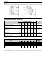
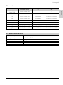
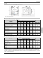
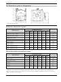
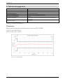
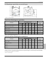
5. Technical data ................................................................................................. 27
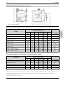
5.1 Dimensions, weights and connections ................................................. 30
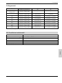
5.2 Ambient conditions ................................................................................... 31
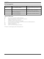
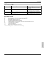
5.3 Approvals ..................................................................................................... 32
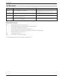
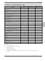
6. Annex A – Standards and Norms ................................................................. 33
7. Annex B – Plastics used ................................................................................ 33
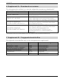
8. Annex C – List of gas types ........................................................................... 34

Honeywell
8 73021678h © Elster GmbH | All rights reserved. Subject to modification
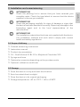
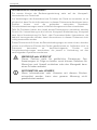
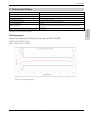
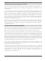
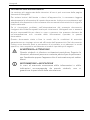
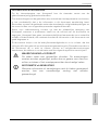
Information on the documentation
The latest version of the operating instructions is available to download from the
Honeywell website.
Please read the information in this document carefully in order to avoid injury to
the user or damage to the device. Moreover, currently valid national standards,
safety regulations and accident prevention regulations must be adhered to.
Should you have any problems understanding the contents of this document,
please contact your local Honeywell branch for support. Honeywell cannot
accept any responsibility for damage to property or personal injuries which are a
result of the information in this document not having been understood properly.
This document helps you to set up the operating conditions in such a way that
the safe and efficient use of the device is assured. In addition, this document also
specifies points and safety measures which must be particularly observed and
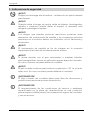
which are indicated using the following symbols:
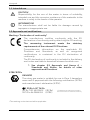
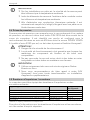
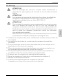
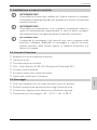
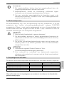
WARNING or CAUTION
This symbol warns of dangerous situations. Failure to follow the
instructions could result in danger to people and the
environment or the meter could suffer damage.
INFORMATION or NOTE
Accurate measurement cannot be ensured if information or
notes with this symbol are ignored.

Honeywell
73021678h © Elster GmbH | All rights reserved. Subject to modification 9
English
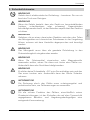
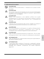
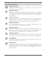
1. Safety instructions
WARNING!
Danger of electrostatic discharge – only use a damp cloth to clean.
WARNING!
If there is danger that the device can be damaged from falling
(pointed, sharp-edged or heavy) objects, the operator must protect
the device.
WARNING!
Exposure to danger which can result from a chemical reaction
between parts of the meter and chemical substances in the vicinity
must be discussed with the manufacturer and the cause must be
eliminated.
WARNING!
The meter must be included in the equipotential bond by
connecting it to the grounded pipeline.
WARNING!
If you wish to add odorants or use solenoid valves, please always fit
them downstream of the meter only. Otherwise, the device may be
damaged.
WARNING!
The gas must not contain suspended particles > 50 µm. In
addition, the gas must be dry. Otherwise, the meter may be
damaged.
INFORMATION!
The flow through the meter must be free of vibrations and
pulsations in order to avoid measuring errors.
INFORMATION!
Compliance with the specified operating and ambient conditions
as indicated on the type label is absolutely essential for safe
operation of the meter and additional equipment.

Honeywell
10 73021678h © Elster GmbH | All rights reserved. Subject to modification
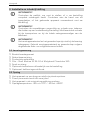
1.1 Intended use
CAUTION!
Responsibility for the use of the meter in terms of suitability,
intended use and the corrosion resistance of the materials to the
medium is solely in the hands of the operator.
INFORMATION!
The manufacturer shall not be liable for damage cause
d by
improper or inappropriate use.
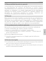
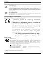
1.2 Approvals and certifications
Marking / Declaration of conformity*
The manufacturer certifies conformity with the EU
declaration of conformity and by attaching the CE marking.
The measuring instrument meets the statutory
requirements of the relevant EU Directives.
Comprehensive information on the applicable EU
Directives and Standards, as well as recognized
certifications, is contained in the EU declaration of
conformity.
The EU declaration of conformity is included in the delivery
and is also available to download at www.docuthek.com.
See chapter 5.3 Approvals and Annex A –
Standards and Norms, for details of other
approvals and Directives.
ATEX/IECEx
DANGER!
The rotary gas meter is suitable for use in Zone 1 hazardous
areas and is approved with the following certification (IECEx)
and manufacturer’s declaration (ATEX):
II 2G Ex h IIC T4 Gb
IECEx TUR 16.0042X (IECEx)
557/Ex-Ab 2664/16 (ATEX)
TÜV Rheinland Industrieservice GmbH
Am Grauen Stein | 51105 Köln | Germany
* The marking on the device shall be applicable.

Honeywell
73021678h © Elster GmbH | All rights reserved. Subject to modification 11
English
1.3 Copyright and data protection
This document has been created with the greatest possible care. No liability
is assumed for the accuracy, completeness or currency of the contents.
The contents and works produced in this document are subject to copyright.
Contributions by third parties are identified as such. The reproduction,
processing, distribution and any form of use beyond that which is permitted
by copyright require the written authorization of the respective author or the
manufacturer. The manufacturer strives to always respect the copyright of
others or to use his own or licence-free works.
We would like to point out that data transfer via the Internet (e.g. through e-
mail communication) can be subject to breaches in security. It is not
possible to provide complete protection against access by third parties.
1.4 Exemption from liability
The manufacturer shall not be liable for damage of any type caused by the
use of this product, including but not restricted to, direct, indirect or
incidental damage and its consequences.
This exemption from liability does not apply if the manufacturer has acted
intentionally or with gross negligence. In the event that any applicable law
does not allow such restrictions on implied warranties for defects, or the
exclusion or limitation of certain payments for damages, and should such
law apply to you, the above-mentioned exemption from liability, exclusions
or limitations may not apply to you in part or in whole.
For every product purchased, the warranty is valid in accordance with the
corresponding product documentation as well as the conditions of sale and
delivery of the manufacturer.
The manufacturer reserves the right to amend without prior notice the
contents of the documents, including this exemption from liability, in any
form and at any point in time, and for any reason, and shall in no way be liable
for any possible consequences of such amendments.

Honeywell
12 73021678h © Elster GmbH | All rights reserved. Subject to modification
1.5 Product liability and guarantee
The responsibility as to whether the measuring instrument is suitable for the
intended use is that of the operator. The manufacturer cannot accept any
liability for the consequences of misuse by the operator. Improper
installation or operation of the measuring instruments (systems) will render
the warranty void. Furthermore, the relevant “General Terms and Conditions”
which form the basis of the purchase contract also apply.
1.6 Personnel
This manual is aimed at personnel who have adequate specialist and
technical knowledge (in Germany, for instance, in accordance with DVGW
Codes of Practice 492 and 495 or comparable technical regulations) on the
basis of their training and experience in the sector of energy and gas
distribution.
1.7 Intended use and field of application
This product is intended to be used for the calibratable volumetric metering
of
flammable gases: natural gas/propane/butane
non-flammable gases: air/nitrogen/inert gases
Other areas of application or media, see Annex C – List of gas types or
on request
This product is not intended for
metering aggressive gases, e.g. biogas or sewage gases, oxygen or
acetylene.
1.8 Legal declarations
The metrological conformity assessment is based on the regulations of
the country concerned, in which the measuring instrument will be used.
The period of validity of calibration is based on the regulations of the
country concerned, in which the measuring instrument will be used.

Honeywell
73021678h © Elster GmbH | All rights reserved. Subject to modification 13
English
1.9 Recycling and environmental protection
Honeywell has designed the transport packaging of the measuring
instrument to be environmentally friendly. Packaging materials are always
selected consistently with a view to recycling. The cardboard items used
constitute secondary raw materials for the paperboard and paper industry.
The Instapak® foam packaging is recyclable and can be reused.
Plastic sheeting and strips/bands are also made of recyclable plastic. At
Honeywell, subsequent recycling and disposal are already elements of the
product development process. When selecting the materials, we allow for
reusability of the materials, suitability of materials and subassemblies for
dismantling and separation, and the risks of environmental pollution and
health risks when recycling and dumping on landfill sites. The measuring
instruments mainly consist of metallic materials which can be melted down
again in steelworks and metallurgical plants and which can thus be reused a
virtually unlimited number of times. The plastics used are listed in Annex B
to ensure that the materials can be sorted and separated for the purposes of
subsequent recycling. Like all mineral oils (e.g. for motor vehicles), the oil
supplied with the device must be disposed of in an environmentally sound
way.

Honeywell
14 73021678h © Elster GmbH | All rights reserved. Subject to modification
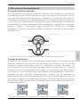
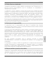
2. Structure and function
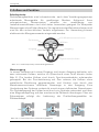
Operating principle
Rotary gas meters are volume-measuring devices for gaseous media which
operate according to the positive displacement principle. Due to their
volumetric measuring principle, their functioning is not influenced by the
installation and they are therefore ideal for compact measuring systems
without an inlet section. They record the gas volume at operating conditions
and are approved for custody transfer applications. Electronic volume
conversion devices can be used in order to convert the volume.
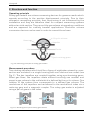
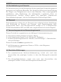
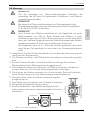
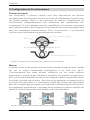
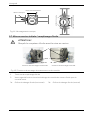
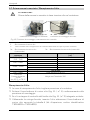
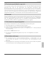
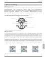
Measurement procedure
Two rotating impellers which look like a figure of eight when viewed in cross-
section are mounted in a single housing with one inlet and one outlet (see
Fig. 1). The two impellers are coupled together using synchronizing gears.
When gas flows, the impellers rotate without touching one another and
propel a gas volume to the outlet which is defined by the cyclic volume. One
rotation of the system thus corresponds to a defined gas volume. The
revolutions of the impellers are transferred to the mechanical index via a
reducing gear and a magnetic coupler. The rotary gas meter is adjusted
using a pair of gears in the index.
Fig. 1b | Working principle of rotary gas meters
Fig. 1a | Working principle of rotary gas meters
Housing
Inlet
Outlet
¼ cyclic volume
Impeller
Synchronizing gears

Honeywell
73021678h © Elster GmbH | All rights reserved. Subject to modification 15
English
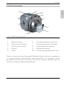
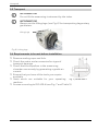
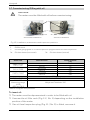
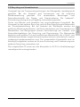
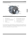
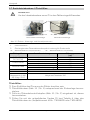
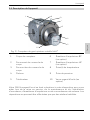
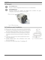
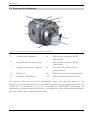
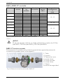
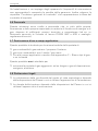
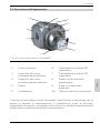
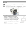
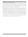
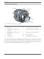
2.1 Device description
1
Meter housing
6
LF pulse generator (optional)
2
Housing cover (front)
7
HF pulse generator (optional)
3 Housing cover (rear) 8 Temperature test point(s)
4
Pistons
9
Pressure test point
5
Index
10
Oil-level gauge glass (optional)
Please contact your local Honeywell Customer Service Centre for assistance
in commissioning, maintenance and installation of encoders, pulse
generators and volume conversion devices for instance. Repairs may be
carried out only by authorized workshops.
Fig. 2 | RABO® rotary gas meter
1
2
3
4
5
6
7
8
9
10

Honeywell
16 73021678h © Elster GmbH | All rights reserved. Subject to modification
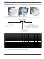
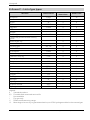
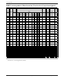
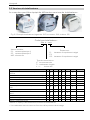
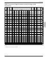
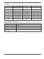
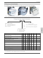
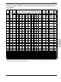
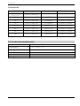
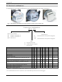
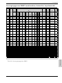
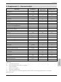
2.2 Index versions
The meter can be equipped with various index versions:
Index type code:
xxx x – xxx
Property:
S1
S1V
S1D
S2
S2V
S2D
MI-2
MI-2D
Mechanical roller index, 8-digit
•
•
-
•
•
-
•
-
2 x mechanical roller index, 8-digit1)
-
-
•
-
-
•
-
•
Index, can be turned through 355°
•
•
•
•
•
•
•
•
Protection class IP 67
•
•
•
•
•
•
•
•
45° reading
•
-
-
•
-
-
•
-
Vertical reading
-
•
•
-
•
•
•
•
Connection for external
pulse generator IN-S
or IN-W
• • • - - - • •
Suitable for internal pulse generator IN-Cxx
-
-
-
•
•
•
-
-
S1xR internal reed contact pulse generator
-
•
•
•
•
•
-
-
Optional: mechanical index drive
-
-
-
-
-
-
•
-
Optional: desiccant cartridge
-
-
-
-
-
-
•
•
Optional: ENCODER S1
•
•
•
-
-
-
•
•
Table 1 | Overview of the various index versions
1) One index is covered depending on the installation position.
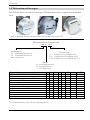
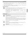
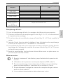
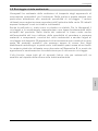
Model version:
S1: plastic version 1
S2: plastic version 2
MI2:
aluminium
Type:
V: vertical reading
D: double index
“ ”: 45° reading
Extensions:
R: integrated pulse generator E1
R3: integrated pulse generator 2xE1
C11: integrated pulse generator IN-
Fig. 3 | Index examples (left: S1D, centre: S1V, right: S2)

Honeywell
73021678h © Elster GmbH | All rights reserved. Subject to modification 17
English
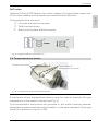
SxD index:
Indexes S1D and S2D feature two roller indexes. A hinged plate covers one
of the roller indexes and at same time shows the flow direction.
Changing the flow direction:
Unscrew the two front screws.
Fold the plate down.
Resecure the plate with the screws.
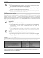
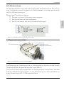
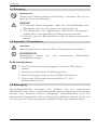
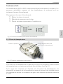
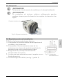
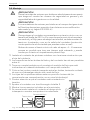
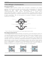
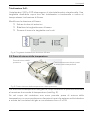
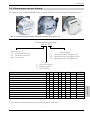
2.3 Temperature test points
A maximum of two temperature sensors may be used to measure the gas
temperature in the meter housing (see Fig. 5).
If no temperature test points are provided in the meter housing, external
temperature measurements must be taken in the pipe upstream of the gas
meter at a distance of up to 2 x DN.
Fig. 5 | Temperature and pressure test points
Fig. 4 | Hinged plate for flow direction
Thermowells for
temperature test points
Pressure test points

Honeywell
18 73021678h © Elster GmbH | All rights reserved. Subject to modification
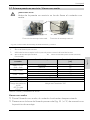
NOTE!
In outdoor measuring systems, the result of measurement may
be influenced by the ambient temperature.
Insulate measuring elements outside the pipe adequately to
prevent ambient temperature influences.
Fill the thermowell(s) with a heat-conductive fluid or paste to
achieve optimum thermal conduction.
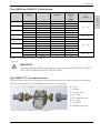
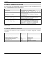
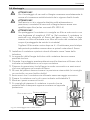
2.4 Pressure test points
A straight male coupling which complies with DIN 2353 is provided on the
meter housing to act as a pressure test point, for example to connect a
pressure sensor. It is marked pm/pr and is designed for connecting Ø 6 mm
steel tubes to DIN EN 10305-1 (e.g. steel grade E235) or flexible pressure
tubes from Honeywell.
CAUTION!
Danger to functional safety!
Functional safety and reliability are ensured only if the material
combination of the union component and the pipe are
intermatched.
The straight male coupling must not be connected to pipes
made of stainless steel or pipes made of non-ferrous materials.
NOTE!
Only use original Parker-Ermeto or Voss pipe unions.
We recommend that you contact our local Honeywell Customer
Service Centre for conversion work and when installing
additional devices.
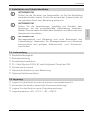
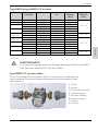
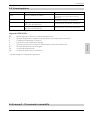
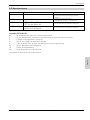
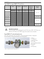
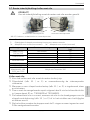
2.5 Pulse generators/Encoders
The meter may be fitted with the following pulse generators or encoders:
Device type:
Manufacturer:
Device designation:
Low-frequency pulse generator (LF)
Elster GmbH
IN-Sxx
Low-frequency pulse generator (LF)
Elster GmbH
IN-Cxx
Low-frequency pulse generator (LF)
Elster GmbH
S1xRx
High-frequency pulse generator (HF)
Pepperl & Fuchs
SJ2-N
Encoder
Elster GmbH
ENCODER S1
Table 2 | Overview of pulse generators
Further information on the pulse generators and encoders is provided in
the separate instruction manuals.

Honeywell
73021678h © Elster GmbH | All rights reserved. Subject to modification 19
English
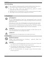
3. Installation and commissioning
INFORMATION!
Check the packing list to ensure that you have received your
complete order. Check the type labels to ensure that the device
supplied is the one you ordered.
INFORMATION!
Check the packaging carefully for signs of damage or signs that
the device has been handled incorrectly. Report any damage to the
forwarding agent and to the local representative of the
manufacturer.
INFORMATION!
The installation material and tools are not supplied with the device.
Use installation material and tools which comply with current
health and safety regulations.
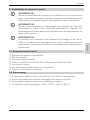
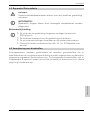
3.1 Scope of delivery
Ordered measuring instrument
Instruction manual
Product documentation
Oil – Shell Morlina S2 BL 10 or Molyduval Chemlube 315
Syringe and hose
Optional accessories depending on the purchase order
Optional: calibration certificate
3.2 Storage
Store the device in a dry and dust-free location.
Avoid constant direct sunlight.
Store the device in its original packaging.
Storage temperature: -40 to +70°C / -40 to +158°F.

Honeywell
20 73021678h © Elster GmbH | All rights reserved. Subject to modification
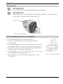
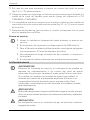
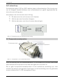
3.3 Transport
INFORMATION!
Do not lift the measuring instrument by the index.
INFORMATION!
Always use the lifting lugs (see Fig. 6) for transporting large rotary
gas meters.
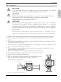
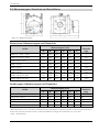
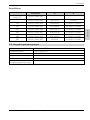
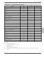
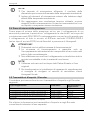
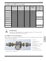
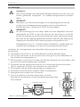
3.4 Requirements to be met before installation
Remove sealing caps and foils.
Check the meter and accessories for signs of
transport damage.
Check that the impellers in the measuring
chamber move easily by generating a gentle air
current.
Ensure that you have all the tools you require
available.
Seals which are suitable for your operating
medium.
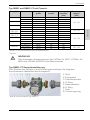
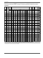
Screws according to ISO 4014 (see Fig. 7 and Table 3)
Fig. 7 | Thread reach C
Fig. 6 | Lifting lugs
Lifting lugs
Seite wird geladen ...
Seite wird geladen ...
Seite wird geladen ...
Seite wird geladen ...
Seite wird geladen ...
Seite wird geladen ...
Seite wird geladen ...
Seite wird geladen ...
Seite wird geladen ...
Seite wird geladen ...
Seite wird geladen ...
Seite wird geladen ...
Seite wird geladen ...
Seite wird geladen ...
Seite wird geladen ...
Seite wird geladen ...
Seite wird geladen ...
Seite wird geladen ...
Seite wird geladen ...
Seite wird geladen ...
Seite wird geladen ...
Seite wird geladen ...
Seite wird geladen ...
Seite wird geladen ...
Seite wird geladen ...
Seite wird geladen ...
Seite wird geladen ...
Seite wird geladen ...
Seite wird geladen ...
Seite wird geladen ...
Seite wird geladen ...
Seite wird geladen ...
Seite wird geladen ...
Seite wird geladen ...
Seite wird geladen ...
Seite wird geladen ...
Seite wird geladen ...
Seite wird geladen ...
Seite wird geladen ...
Seite wird geladen ...
Seite wird geladen ...
Seite wird geladen ...
Seite wird geladen ...
Seite wird geladen ...
Seite wird geladen ...
Seite wird geladen ...
Seite wird geladen ...
Seite wird geladen ...
Seite wird geladen ...
Seite wird geladen ...
Seite wird geladen ...
Seite wird geladen ...
Seite wird geladen ...
Seite wird geladen ...
Seite wird geladen ...
Seite wird geladen ...
Seite wird geladen ...
Seite wird geladen ...
Seite wird geladen ...
Seite wird geladen ...
Seite wird geladen ...
Seite wird geladen ...
Seite wird geladen ...
Seite wird geladen ...
Seite wird geladen ...
Seite wird geladen ...
Seite wird geladen ...
Seite wird geladen ...
Seite wird geladen ...
Seite wird geladen ...
Seite wird geladen ...
Seite wird geladen ...
Seite wird geladen ...
Seite wird geladen ...
Seite wird geladen ...
Seite wird geladen ...
Seite wird geladen ...
Seite wird geladen ...
Seite wird geladen ...
Seite wird geladen ...
Seite wird geladen ...
Seite wird geladen ...
Seite wird geladen ...
Seite wird geladen ...
Seite wird geladen ...
Seite wird geladen ...
Seite wird geladen ...
Seite wird geladen ...
Seite wird geladen ...
Seite wird geladen ...
Seite wird geladen ...
Seite wird geladen ...
Seite wird geladen ...
Seite wird geladen ...
Seite wird geladen ...
Seite wird geladen ...
Seite wird geladen ...
Seite wird geladen ...
Seite wird geladen ...
Seite wird geladen ...
Seite wird geladen ...
Seite wird geladen ...
Seite wird geladen ...
Seite wird geladen ...
Seite wird geladen ...
Seite wird geladen ...
Seite wird geladen ...
Seite wird geladen ...
Seite wird geladen ...
Seite wird geladen ...
Seite wird geladen ...
Seite wird geladen ...
Seite wird geladen ...
Seite wird geladen ...
Seite wird geladen ...
Seite wird geladen ...
Seite wird geladen ...
Seite wird geladen ...
Seite wird geladen ...
Seite wird geladen ...
Seite wird geladen ...
Seite wird geladen ...
Seite wird geladen ...
Seite wird geladen ...
Seite wird geladen ...
Seite wird geladen ...
Seite wird geladen ...
Seite wird geladen ...
Seite wird geladen ...
Seite wird geladen ...
Seite wird geladen ...
Seite wird geladen ...
Seite wird geladen ...
Seite wird geladen ...
Seite wird geladen ...
Seite wird geladen ...
Seite wird geladen ...
Seite wird geladen ...
Seite wird geladen ...
Seite wird geladen ...
Seite wird geladen ...
Seite wird geladen ...
Seite wird geladen ...
Seite wird geladen ...
Seite wird geladen ...
Seite wird geladen ...
Seite wird geladen ...
Seite wird geladen ...
Seite wird geladen ...
Seite wird geladen ...
Seite wird geladen ...
Seite wird geladen ...
Seite wird geladen ...
Seite wird geladen ...
Seite wird geladen ...
Seite wird geladen ...
Seite wird geladen ...
Seite wird geladen ...
Seite wird geladen ...
Seite wird geladen ...
Seite wird geladen ...
Seite wird geladen ...
Seite wird geladen ...
Seite wird geladen ...
Seite wird geladen ...
Seite wird geladen ...
Seite wird geladen ...
Seite wird geladen ...
Seite wird geladen ...
Seite wird geladen ...
Seite wird geladen ...
Seite wird geladen ...
Seite wird geladen ...
Seite wird geladen ...
Seite wird geladen ...
Seite wird geladen ...
-
 1
1
-
 2
2
-
 3
3
-
 4
4
-
 5
5
-
 6
6
-
 7
7
-
 8
8
-
 9
9
-
 10
10
-
 11
11
-
 12
12
-
 13
13
-
 14
14
-
 15
15
-
 16
16
-
 17
17
-
 18
18
-
 19
19
-
 20
20
-
 21
21
-
 22
22
-
 23
23
-
 24
24
-
 25
25
-
 26
26
-
 27
27
-
 28
28
-
 29
29
-
 30
30
-
 31
31
-
 32
32
-
 33
33
-
 34
34
-
 35
35
-
 36
36
-
 37
37
-
 38
38
-
 39
39
-
 40
40
-
 41
41
-
 42
42
-
 43
43
-
 44
44
-
 45
45
-
 46
46
-
 47
47
-
 48
48
-
 49
49
-
 50
50
-
 51
51
-
 52
52
-
 53
53
-
 54
54
-
 55
55
-
 56
56
-
 57
57
-
 58
58
-
 59
59
-
 60
60
-
 61
61
-
 62
62
-
 63
63
-
 64
64
-
 65
65
-
 66
66
-
 67
67
-
 68
68
-
 69
69
-
 70
70
-
 71
71
-
 72
72
-
 73
73
-
 74
74
-
 75
75
-
 76
76
-
 77
77
-
 78
78
-
 79
79
-
 80
80
-
 81
81
-
 82
82
-
 83
83
-
 84
84
-
 85
85
-
 86
86
-
 87
87
-
 88
88
-
 89
89
-
 90
90
-
 91
91
-
 92
92
-
 93
93
-
 94
94
-
 95
95
-
 96
96
-
 97
97
-
 98
98
-
 99
99
-
 100
100
-
 101
101
-
 102
102
-
 103
103
-
 104
104
-
 105
105
-
 106
106
-
 107
107
-
 108
108
-
 109
109
-
 110
110
-
 111
111
-
 112
112
-
 113
113
-
 114
114
-
 115
115
-
 116
116
-
 117
117
-
 118
118
-
 119
119
-
 120
120
-
 121
121
-
 122
122
-
 123
123
-
 124
124
-
 125
125
-
 126
126
-
 127
127
-
 128
128
-
 129
129
-
 130
130
-
 131
131
-
 132
132
-
 133
133
-
 134
134
-
 135
135
-
 136
136
-
 137
137
-
 138
138
-
 139
139
-
 140
140
-
 141
141
-
 142
142
-
 143
143
-
 144
144
-
 145
145
-
 146
146
-
 147
147
-
 148
148
-
 149
149
-
 150
150
-
 151
151
-
 152
152
-
 153
153
-
 154
154
-
 155
155
-
 156
156
-
 157
157
-
 158
158
-
 159
159
-
 160
160
-
 161
161
-
 162
162
-
 163
163
-
 164
164
-
 165
165
-
 166
166
-
 167
167
-
 168
168
-
 169
169
-
 170
170
-
 171
171
-
 172
172
-
 173
173
-
 174
174
-
 175
175
-
 176
176
-
 177
177
-
 178
178
-
 179
179
-
 180
180
-
 181
181
-
 182
182
-
 183
183
-
 184
184
-
 185
185
-
 186
186
-
 187
187
-
 188
188
-
 189
189
-
 190
190
-
 191
191
-
 192
192
-
 193
193
-
 194
194
-
 195
195
-
 196
196


in anderen Sprachen
- français: Elster RABO Mode d'emploi
- español: Elster RABO Instrucciones de operación
- italiano: Elster RABO Istruzioni per l'uso
- Nederlands: Elster RABO Handleiding
Verwandte Artikel
-
Elster S1D Bedienungsanleitung
-
-
-
-
-
-
-
-
-
Andere Dokumente
-
Honeywell IN-Sxx, S1xRx, S2xRx, QA E1, RVG-ST E1 Bedienungsanleitung
-
-
-
Zenner reed sensor Installationsanleitung
-
-
-
-
 Krom Schroder TZI 5-15/100 Benutzerhandbuch
-
-
