
Installation Guide
Ceiling Mount Access Point


CONTENTS
Deutsch ................................................................................................1
English .................................................................................................. 7
Español...............................................................................................13
Eλληνικά .............................................................................................19
Français .............................................................................................. 25
Italiano ................................................................................................31
Português ...........................................................................................37
Suomi .................................................................................................43
Nederlands .........................................................................................49
Svenska .............................................................................................. 55
Norsk ..................................................................................................61
Dansk .................................................................................................67

1
Deutsch
Hinweis: Die Bilder können vom tatsächlichen Aussehen des Produkts abweichen.
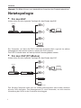
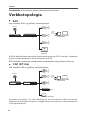
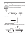
Netztopologie
■
Für den EAP
Unten sehen Sie eine typische Topologie für den Einsatz des EAP
.
Controller-Host
Router Switch
Internet
Clients
EAP
EAP
EAP
EAP Controller
Ein Computer, auf dem die EAP-Controller-Software läuft, egal ob im selben
Netzsegment oder einem anderen, steuert die EAPs zentral.
Der EAP-Controller kann auf www.tp-link.de heruntergeladen werden.
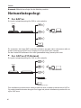
■
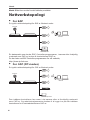
Für den CAP (FIT-Modus)
Unten sehen Sie eine typische Topologie für den Einsatz des CAP
.
Router Switch
Internet
Clients
CAP
CAP
CAP
Management-PC
WLAN-Controller
Der WLAN-Controller kann sich im selben Netzsegment oder einem anderen
als die CAPs befinden. Der Management-PC wird verwendet, um sich zwecks
Verwaltung der CAPs in den Controller einzuloggen.

2
Deutsch
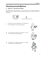
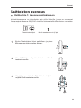
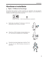
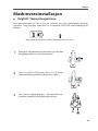
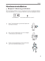
Hardwareinstallation
■
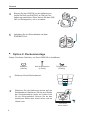
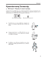
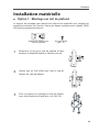
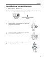
Option 1: Deckenmontage
Die Deckenschienenmontage ist nur für Geräte, die mit folgendem Zubehör
geliefert wurden, möglich. Folgen Sie diesen Schritten, um Ihren EAP/CAP zu
installieren
:
Deckenclip M3×6-Schrauben (5 Stück)
1
Positionieren Sie den Deckenclip und schieben Sie
den beweglichen Teil der Basis entgegen.
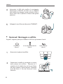
2
Verwenden Sie eine M3×6-Schraube, um den
Clip an die Decke anzuschrauben.
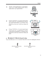
3
Bringen Sie die Halterung mittels vier M3x6-
Schrauben an den Deckenclip an.

3
Deutsch
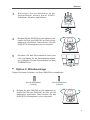
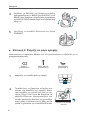
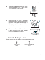
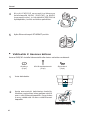
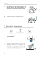
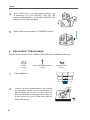
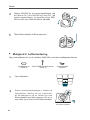
4
Bringen Sie den EAP/CAP an die Halterung an,
indem Sie Pfeil (am EAP/CAP) an Pfeil (an der
Halterung) ausrichten. Dann drehen Sie den EAP/
CAP im Uhrzeigersinn, bis er einrastet.
5
Verbinden Sie ein Ethernetkabel mit dem
ETHERNET-Port.
■
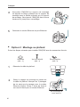
Option 2: Deckenmontage
Folgen Sie diesen Schritten, um Ihren EAP/CAP zu installieren
:
Scheiben
(3 Stück)
M3×30-Schrauben
(3 Stück)
Flügelmuttern
(3 Stück)
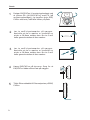
1
Entfernen Sie die Deckenkachel.
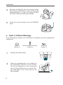
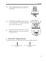
2
Platzieren Sie die Halterung zentral auf der
Deckenkachel. Markieren Sie die drei Stellen
der Schraubenlöcher sowie ein 10mm-Loch
für ein Ethernetkabel. Bohren Sie an den
markierten Stellen drei 4mm-Löcher und ein
10mm-Loch.
X3
Loch für ein
Ethernetkabel

4
Deutsch
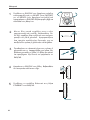
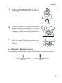
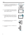
3
Befestigen Sie die Halterung an der
Deckenkachel mittels dreier M3x30-
Schrauben, Scheiben und Muttern.
4
Bringen Sie den EAP/CAP an die Halterung an,
indem Sie Pfeil (am EAP/CAP) an Pfeil (an der
Halterung) ausrichten. Dann drehen Sie den
EAP/CAP im Uhrzeigersinn, bis er einrastet.
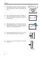
5
Schieben Sie das Ethernetkabel durch das
Loch und bauen Sie die Deckenkachel wieder
ein. Verbinden Sie das Ethernetkabel mit dem
ETHERNET-Port.
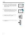
■
Option 3: Wandmontage
Folgen Sie diesen Schritten, um Ihren EAP/CAP zu installieren
:
M3×28-Wanddübel
(4 Stück)
M3×20-Schrauben
(4 Stück)
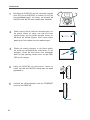
1
Bringen Sie den EAP/CAP an die Halterung an,
indem Sie Pfeil (am EAP/CAP) an Pfeil (an der
Halterung) ausrichten. Dann drehen Sie den
EAP/CAP im Uhrzeigersinn, bis er einrastet.

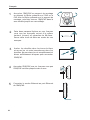
5
Deutsch
2
Markieren Sie zwei 98,6mm voneinander
entfernte, in gleicher Höhe befindliche Stellen
an der Wand z.B. mittels eines Bleistiftes.
Bohren Sie zentral zwei 6mm-Löcher an den
markierten Stellen.
98.6mm
3
Schieben Sie die Dübel in die Löcher und
drehen Sie die Schrauben hinein. Lassen Sie
die Köpfe ein wenig herausschauen, so dass
Sie den EAP/CAP daran aufhängen können.
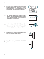
4
Hängen Sie den EAP/CAP an die Schrauben.
Stellen Sie sicher, dass er fest sitzt.
5
Verbinden Sie das Ethernetkabel mit dem
ETHERNET-Port.

6
Deutsch
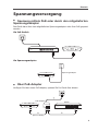
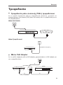
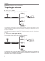
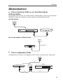
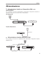
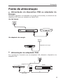
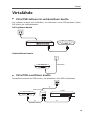
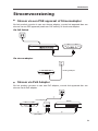
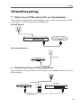
Spannungsversorgung
■
Speisung mittels PoE oder durch den mitgelieferten
Spannungsadapter
Das Gerät kann über den mitgelieferten Spannungsadapter oder über PoE gespeist
werden.
Via PoE-Switch
Via Spannungsadapter
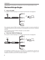
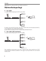
■
Über PoE-Adapter
Verfügen Sie über einen PoE-Adapter, speisen Sie Ihr Gerät über diesen.
1
3
PoE LAN
2
PoE-Switch
Spannungsadapter
PoE-Adapter
(Bis zu 100m)
Switch

7
English
Note: The image may differ from the actual product.
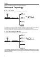
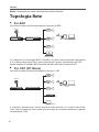
Network Topology
■
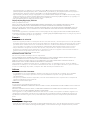
For the EAP
A typical network topology for the EAP is shown below.
Controller Host
Router Switch
Internet
Clients
EAP
EAP
EAP
EAP Controller
A computer running the EAP Controller software, which can be in the same or
different subnet with the EAPs, is used to centrally manage the EAPs.
You can get the EAP Controller software from our website http://www.tp-link.com.
■
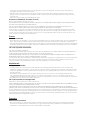
For the CAP (FIT Mode)
A typical network topology for the CAP is shown below.
Router Switch
Internet
Clients
CAP
CAP
CAP
Management Host
Wireless Controller
The wireless controller can be in the same or different subnet with the CAPs.
And the management host is used to log in to the wireless controller to centrally
manage the CAPs.

8
English
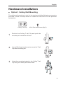
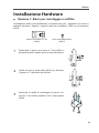
Hardware Installation
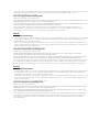
■
Option1
:
Ceiling Rail Mounting
The ceiling rail mounting is only for the devices with the following accessories
provided. Follow the steps below to install the EAP/CAP with the provided
accessories:
Ceiling T-rail Clip M3×6 Pan-head Screws (Qty.5)
1
Position the Ceiling T-rail Clip and push the
movable part toward the rail base.
2
Use an M3×6 pan-head screw to secure the T-rail
Clip onto the ceiling rail.
3
Attach the mounting bracket to the Ceiling T-rail
Clip using four M3x6 pan-head screws.

9
English
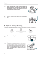
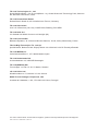
4
Attach the EAP/CAP to the mounting bracket by
aligning arrow (on the EAP/CAP) with arrow (on
the mounting bracket), then rotate the EAP/CAP
clockwise until it locks into place.
5
Connect the Ethernet cable to the ETHERNET
port.
■
Option2
:
Ceiling Mounting
Follow the steps below to install the EAP/CAP with the provided accessories:
Washers
(Qty.3)
M3×30 Pan-head Screws
(Qty.3)
Wing Nuts
(Qty.3)
1
Remove the ceiling tile.
2
Place the mounting bracket in the center
of the ceiling tile. Mark the three positions
of the screw holes and a 10mm hole for
the Ethernet cable to feed through. Drill
three 4mm holes and a 10mm hole for the
Ethernet cable.
X3
Hole for Ethernet cable

10
English
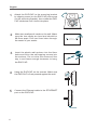
3
Secure the mounting bracket to the ceiling
tile using three M3x30 pan-head screws,
washers and wing nuts.
4
Attach the EAP/CAP to the mounting bracket
by aligning arrow (on the EAP/CAP) with
arrow (on the mounting bracket), then rotate
the EAP/CAP clockwise until it locks into
place.
5
Feed the Ethernet cable through the hole and
set the ceiling tile back into place. Connect
the Ethernet cable to the ETHERNET port.
■
Option3
:
Wall Mounting
Follow the steps below to install the EAP/CAP with the provided accessories:
M3×28 Plastic Wall Anchors
(Qty.4)
M3×20 Self-tapping Screws
(Qty.4)

11
English
1
Attach the EAP/CAP to the mounting bracket
by aligning arrow (on the EAP/CAP) with arrow
(on the mounting bracket), then rotate the EAP/
CAP clockwise until it locks into place.
2
Make two small pencil marks on the wall. Make
sure the two marks are level and should be
98.6mm apart. Drill two 6mm holes through
the center of your marks.
98.6mm
3
Insert the plastic wall anchors into the 6mm
holes and drive the self-tapping screws into
the anchors. Do not drive the screws all the
way in and leave enough clearance to hang
the EAP/CAP.
4
Hang the EAP/CAP on the screws. Make sure
the EAP/CAP is firmly seated against the wall.
5
Connect the Ethernet cable to the ETHERNET
port on the EAP/CAP.

12
English
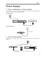
Power Supply
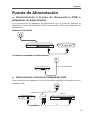
■
Power via PSE Device or Power Adapter
If the product is provided with a power adapter, power the device via a PSE device
(such as a PoE switch) or the power adapter.
Via PoE Switch
Via Power Adapter
■
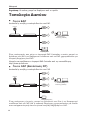
Power via PoE Adapter
If the product is provided with a PoE adapter, power the device via the PoE
adapter.
1
3
PoE LAN
2
PoE Switch
PoE Adapter
(Up to 100m)
Switch
Power Adapter

13
Español
Nota: La imagen puede cambiar respecto al producto actual.
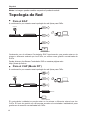
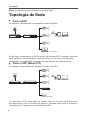
Topología de Red
■
Para el EAP
A continuación, se muestra una topología de red típica para EAPs
.
Host Controlador
Router Switch
Internet
Clientes
EAP
EAP
EAP
EAP Controller
Ordenador con el software Controlador EAP funcionando, que puede estar en la
misma o diferente subred que los EAPs, se utiliza como gestión centralizada de
EAPs.
Puede obtener el software Controlador EAP en nuestra página web:
http://www.tp-link.es
■
Para el CAP (Modo FIT)
A continuación, se muestra una topología de red típica para CAPs
.
Router Switch
Internet
Clientes
CAP
CAP
CAP
Host de Gestión
Controlador Inalámbrico
El controlador inalámbrico puede estar en la misma o diferente subred que los
CAPs. El host de gestión se utiliza para acceder al controlador inalámbrico para
gestionar de manera centralizada los CAPs.

14
Español
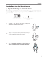
Instalación de Hardware
■
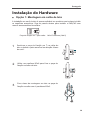
Opción 1: Montaje en Carril de Techo
El montaje en carril de techo es solo para dispositivos que incluyan los siguientes
accesorios. Siga los siguientes pasos para instalar el EAP/CAP con los accesorios
proporcionados
:
Clip de carril en techo Tornillos de cabeza plana
M3×6(5)
1
Coloque el clip de carril en techo y empuje la
parte móvil hacia la base del carril.
2
Utilice un tornillo de cabeza plana M3x6 para fijar
el clip de carril de techo sobre el carril.
3
Fije el soporte de montaje en el clip de carril de
techo con cuatro tornillos de cabeza plana M3x6.

15
Español
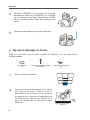
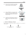
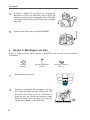
4
Coloque el EAP/CAP en el soporte de montaje
alineando la flecha (en el EAP/CAP) con la flecha
(en el soporte de montaje), después gire el EAP/
CAP en sentido horario hasta que encaje en su
lugar.
5
Conecte el cable Ethernet al puerto Ethernet.
■
Opción 2: Montaje en Techo
Siga los siguientes pasos para instalar el EAP/CAP con los accesorios
proporcionados
:
Arandelas
(3)
Tornillos de cabeza plana
M3×30 (3)
Tuercas de mariposa
(3)
1
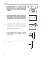
Retire el soporte de techo.
2
Coloque el soporte de montaje en el centro
del soporte de techo. Marque las tres
posiciones de los orificios de los tornillos y
un agujero de 10 mm para el cable Ethernet
de alimentación. Perfore tres orificios de 4
mm y un agujero de 10 mm para el cable
Ethernet.
X3
Agujero para Cable
Ethernet

16
Español
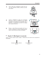
3
Fije el soporte de montaje en el soporte
de techo con tres tornillos de cabeza plana
M3x30, arandelas y tuercas de mariposa
.
4
Coloque el EAP/CAP en el soporte de montaje
alineando la flecha (en el EAP/CAP) con la
flecha (en el soporte de montaje), después
gire el EAP/CAP en sentido horario hasta que
encaje en su lugar.
5
Introduzca el cable Ethernet a través del
agujero y fije el soporte de techo nuevo en
su lugar. Conecte el cable Ethernet al puerto
Ethernet.
■
Opción 3: Montaje en Pared
Siga los siguientes pasos para instalar el EAP/CAP con los accesorios
proporcionados
:
Anclajes de pared de plástico
M3×28 (4)
Tornillos taladradores
M3×20 (4)

17
Español
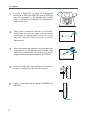
1
Coloque el EAP/CAP en el soporte de montaje
alineando la flecha (en el EAP/CAP) con la
flecha (en el soporte de montaje), después gire
el EAP/CAP en sentido horario hasta que encaje
en su lugar.
2
Realice dos pequeñas marcas de lápiz en la
pared. Asegúrese de que las dos marcas están
al mismo nivel y están separadas 98.6mm.
Perforar dos agujeros de 6 mm en el centro de
las marcas.
98.6mm
3
Inserte los anclajes de plástico para pared
en los agujeros de 6 mm y los tornillos
taladradores en los anclajes. No enrrosque
los tornillos hasta el fondo y deje suficiente
espacio para colgar el EAP/CAP.
4
Cuelgue el EAP/CAP en los tornillos. Asegúrese
de que el EAP/CAP se haya sujetado firmemente
contra la pared.
5
Conecte el cable Ethernet al puerto Ethernet
del EAP/CAP.
Seite wird geladen ...
Seite wird geladen ...
Seite wird geladen ...
Seite wird geladen ...
Seite wird geladen ...
Seite wird geladen ...
Seite wird geladen ...
Seite wird geladen ...
Seite wird geladen ...
Seite wird geladen ...
Seite wird geladen ...
Seite wird geladen ...
Seite wird geladen ...
Seite wird geladen ...
Seite wird geladen ...
Seite wird geladen ...
Seite wird geladen ...
Seite wird geladen ...
Seite wird geladen ...
Seite wird geladen ...
Seite wird geladen ...
Seite wird geladen ...
Seite wird geladen ...
Seite wird geladen ...
Seite wird geladen ...
Seite wird geladen ...
Seite wird geladen ...
Seite wird geladen ...
Seite wird geladen ...
Seite wird geladen ...
Seite wird geladen ...
Seite wird geladen ...
Seite wird geladen ...
Seite wird geladen ...
Seite wird geladen ...
Seite wird geladen ...
Seite wird geladen ...
Seite wird geladen ...
Seite wird geladen ...
Seite wird geladen ...
Seite wird geladen ...
Seite wird geladen ...
Seite wird geladen ...
Seite wird geladen ...
Seite wird geladen ...
Seite wird geladen ...
Seite wird geladen ...
Seite wird geladen ...
Seite wird geladen ...
Seite wird geladen ...
Seite wird geladen ...
Seite wird geladen ...
Seite wird geladen ...
Seite wird geladen ...
Seite wird geladen ...
Seite wird geladen ...
Seite wird geladen ...
Seite wird geladen ...
Seite wird geladen ...
Seite wird geladen ...
-
 1
1
-
 2
2
-
 3
3
-
 4
4
-
 5
5
-
 6
6
-
 7
7
-
 8
8
-
 9
9
-
 10
10
-
 11
11
-
 12
12
-
 13
13
-
 14
14
-
 15
15
-
 16
16
-
 17
17
-
 18
18
-
 19
19
-
 20
20
-
 21
21
-
 22
22
-
 23
23
-
 24
24
-
 25
25
-
 26
26
-
 27
27
-
 28
28
-
 29
29
-
 30
30
-
 31
31
-
 32
32
-
 33
33
-
 34
34
-
 35
35
-
 36
36
-
 37
37
-
 38
38
-
 39
39
-
 40
40
-
 41
41
-
 42
42
-
 43
43
-
 44
44
-
 45
45
-
 46
46
-
 47
47
-
 48
48
-
 49
49
-
 50
50
-
 51
51
-
 52
52
-
 53
53
-
 54
54
-
 55
55
-
 56
56
-
 57
57
-
 58
58
-
 59
59
-
 60
60
-
 61
61
-
 62
62
-
 63
63
-
 64
64
-
 65
65
-
 66
66
-
 67
67
-
 68
68
-
 69
69
-
 70
70
-
 71
71
-
 72
72
-
 73
73
-
 74
74
-
 75
75
-
 76
76
-
 77
77
-
 78
78
-
 79
79
-
 80
80


TP-LINK EAP245 AC1750 V3 WHITE Benutzerhandbuch
- Typ
- Benutzerhandbuch
- Dieses Handbuch eignet sich auch für
in anderen Sprachen
- English: TP-LINK EAP245 AC1750 V3 WHITE User manual
- français: TP-LINK EAP245 AC1750 V3 WHITE Manuel utilisateur
- español: TP-LINK EAP245 AC1750 V3 WHITE Manual de usuario
- italiano: TP-LINK EAP245 AC1750 V3 WHITE Manuale utente
- Nederlands: TP-LINK EAP245 AC1750 V3 WHITE Handleiding
- português: TP-LINK EAP245 AC1750 V3 WHITE Manual do usuário
- dansk: TP-LINK EAP245 AC1750 V3 WHITE Brugermanual
- svenska: TP-LINK EAP245 AC1750 V3 WHITE Användarmanual
