
Quick Installation Guide
Wall-Plate Access Point

CONTENT
Deutsch ............................................................................................................ 1
English ............................................................................................................... 6
Español ...........................................................................................................11
Eλληνικά ......................................................................................................... 16
Français ..........................................................................................................21
Italiano .............................................................................................................26
Português ......................................................................................................31
Suomi ...............................................................................................................36
Nederlands ....................................................................................................41
Svenska ..........................................................................................................46
Norsk................................................................................................................51
Dansk ...............................................................................................................56

1
Deutsch
Hinweis: Für die folgende Einleitung dient der EAP115-Wall als
Beispiel.
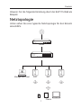
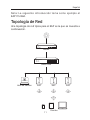
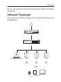
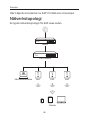
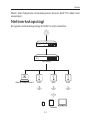
Netztopologie
Unten sehen Sie eine typische Netztopologie für den Einsatz
eines EAPs.
Omada Controller
Router
PoE-Switch
Management-Host EAP EAP EAP
Clients

2
Deutsch
Der EAP kann über ein PoE-Gerät, wie z.B. einen PoE-Switch,
gespeist werden. Ein DHCP-Server (typischerweise ein Router)
ist erforderlich, damit Ihren EAPs und Ihren Clients im lokalen
Netz IP-Adressen zugewiesen werden. Der Management-Host
kann sich im selben Netz wie die EAPs oder in einem anderen
benden.
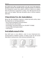
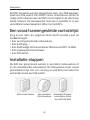
Checkliste für die Installation
Bevor Sie die Installation beginnen, stellen Sie bitte sicher, dass
Sie folgendes zur Verfügung haben:
• Eine bereits installierte Unterputzdose
• Verbundener RJ45-Stecker
• Dreieckiger Schraubendreher (nur für EAP115-Wall)
• Kreuzschlitz-Schraubenzieher
• PoE-Switch
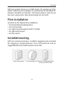
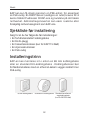
Installationsschritte
Der EAP kann in eine 86mm- oder in eine Standard-EU-
Unterputzdose installiert werden. In dieser muss ein mit einem
PoE-Switch verbundener RJ45-Stecker bendlich sein.
86mm-
Unterputzdose
Standard-EU-
Unterputzdose
Standard US Wandabzweigdose
(nur für EAP225-Wall)

3
Deutsch
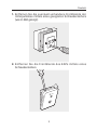
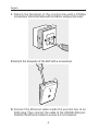
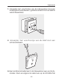
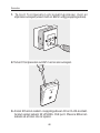
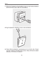
1. Entfernen Sie die eventuell vorhandene Frontblende der
Unterputzdose mittels eines geeigneten Schraubenziehers
(wie im Bild gezeigt).
2. Entfernen Sie die Frontblende des EAPs mittels eines
Schraubenziehers.

4
Deutsch
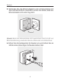
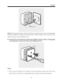
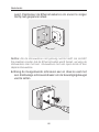
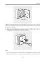
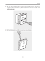
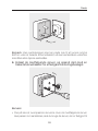
3. Verbinden Sie das Ethernetkabel in der Unterputzdose mit
dem UPLINK+PoE-Port des EAPs. Achten Sie darauf, dass das
Ethernetkabel nicht unter Zug steht.
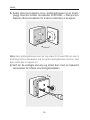
Hinweis: Bietet die Unterputzdose nicht ausreichend Platz für EAP und
Ethernetverbindung, verwenden Sie eine oene oder eine tiefere Dose.
4. Führen Sie die beiliegenden Schrauben ein und drehen Sie sie
mittels eines dreieckigen Schraubenziehers fest.

5
Deutsch
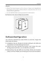
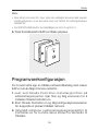
Hinweis:
• Ziehen Sie die Schrauben nicht zu fest an. Passen die mitgelieferten
Schrauben nicht zu Ihrer Unterputzdose, verwenden Sie die mit der
Unterputzdose gelieferten.
• Für den EAP225-Wall, tauschen Sie Schritt 4 mit Schritt 3.
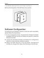
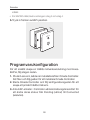
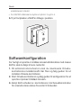
5. Platzieren Sie die Frontblende des EAPs.
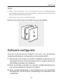
Softwarekonfiguration
Um schnell ein WLAN aus vielen EAPs zu errichten, folgen Sie
bitte diesen Schritten.
1. Installieren Sie die Omada-Controller-Software mit Hilfe des
Assistenten auf dem Management-Host.
2. Starten Sie den Omada-Controller und folgen Sie den
Kongurationsschritten, um ein WLAN zu errichten.
3. Übernehmen Sie die EAPs im Controller mittels der Funktion
Adopt, um ihren Status von Pending auf Connected zu ändern.

6
English
Note: The following introduction takes EAP115-Wall as an
example.
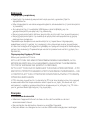
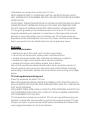
Network Topology
A typical network topology for the EAP is shown below.
Omada Controller
Router
PoE Switch
Management Host EAP EAP EAP
Clients

7
English
The EAP can only be powered by a PSE device, such as a PoE
switch. A DHCP server (typically a router) is required to assign
IP addresses to the EAPs and clients in your local network.
The management host can be in the same or dierent network
segment with the EAPs.
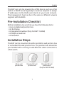
Pre-Installation Checklist
Before installation, be sure that you have the following items:
• A pre-installed wall junction box
• An RJ45 plug
• A triangular screwdriver (Only for EAP115-Wall)
• A Phillips screwdriver
• A PoE switch
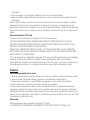
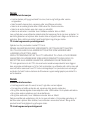
Installation Steps
The EAP can be mounted into either an 86mm wall junction box
or a standard EU wall junction box. The junction box should be
pre-installed with a running-in-wall Ethernet cable connected to
a PoE switch.
86mm wall
junction box
Standard EU wall
junction box
Standard US wall
junction box
(Only for EAP225-Wall)

8
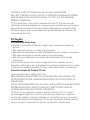
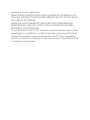
English
1. Detach the faceplate of the junction box with a Phillips
screwdriver (demonstrated with an 86mm wall junction box).
2. Detach the faceplate of the EAP with a screwdriver.
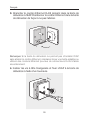
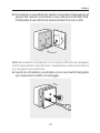
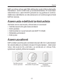
3. Connect the Ethernet cable inside the junction box to an
RJ45 plug. Then connect the cable to the UPLINK+PoE port.
Position the Ethernet cable to ensure it is not strained.

9
English
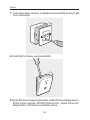
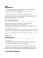
Note: If the junction box does not have enough room to accommodate
the EAP without straining the Ethernet cable, replace the junction box
with an open-end or deeper one.
4. Insert the enclosed screws and tighten them with a triangular
screwdriver to secure the mounting bracket.
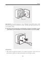
Note:
• Do not over tighten the screws. If the enclosed screws do not t the
junction box, use the screws attached to the junction box instead.

10
English
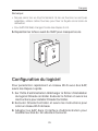
• For EAP225-Wall, switch the order of Step 3 and Step 4.
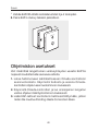
5. Press the faceplate of the EAP back into position.
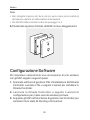
Software Configuration
To quickly set up a wireless network connection with mass EAPs,
please follow the steps below.
1. On the management host, download the Omada Controller
installation le. Run the le and follow the wizard to install the
Omada Controller.
2. Launch the Omada Controller and follow the configuration
wizard to create a primary wireless network.
3. Adopt the EAP devices in the Controller management
interface to change their status from Pending to Connected.

11
Español
Nota: La siguiente introducción toma como ejemplo el
EAP115-Wall.
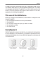
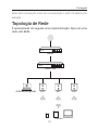
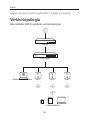
Topología de Red
Una topología de red típica para el EAP es la que se muestra a
continuación.
Omada Controller
Router
Switch PoE
Host de Gestión EAP EAP EAP
Clientes

12
Español
El EAP solo puede ser alimentado por un dispositivo PSE, como
por ejemplo un switch PoE. Se requiere un servidor DHCP
(típicamente un router) para asignar direcciones IP a los EAPs y
clientes de su red local. El host de gestión puede estar o no en
el mismo segmento de red que los EAPs.
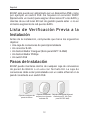
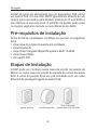
Lista de Verificación Previa a la
Instalación
Antes de la instalación, compruebe que tiene los siguientes
objetos:
• Una caja de conexiones de pared preinstalada
• Un conector RJ45
• Un destornillador trianguar (Solo para EAP115-Wall)
• Un destornillador Phillips
• Un switch PoE
Pasos de Instalación
El EAP puede montarse dentro de cualquier caja de conexiones
de pared de 86mm o en una con formato EU. La caja de
conexiones debe estar preinstalada con un cable ethernet en la
pared conectado a un switch PoE.
Caja de conexiones de
pared de 86mm
Caja de conexiones
de pared con formato
estándar EU
Caja de conexiones de pared
estándar en EE. UU. (Solo
para EAP225-Wall)

13
Español
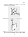
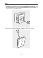
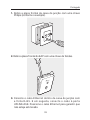
1. Separe la placa frontal de la caja de conexiones con un
destornillador Phillips (demostrado con una caja de
conexiones de pared de 86mm).
2. Separe la placa frontal del EAP con un destornillador.
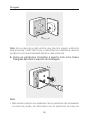
3. Conecte el cable Ethernet dentro de la caja de conexiones
en un conector RJ45. Después conecte un cable al puerto

14
Español
UPLINK+PoE. Coloque el cable Ethernet de tal forma que no
quede oprimido.
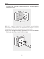
Nota: Si la caja de conexiones no tiene espacio suficiente para
acomodar el EAP sin oprimir el cable Ethernet, cambie la caja de
conexiones por una con el extremo abierto o más profundo.
4. Inserte los tornillos incluidos y apriételos con un destornillador
triangular para jar el soporte de montaje.

15
Español
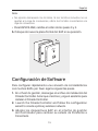
Nota:
• No apriete demasiado los tornillos. Si los tornillos incluidos no se
ajustan a la caja de conexiones, utilice los tornillos conectados a la
caja de conexiones.
•
Para EAP225-Wall, cambie el orden de los pasos 3 y 4.
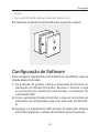
5. Coloque de nuevo la placa frontal del EAP en su posición.
Configuración de Software
Para configurar rápidamente una conexión de red inalámbrica
con muchos EAPs, por favor siga los siguientes pasos.
1. En el host de gestión, descargue el archivo de instalación del
Omada Controller. Arranque el archivo y siga el asistente para
instalar el Omada Controller.
2. Launch the Omada Controller and follow the configuration
wizard to create a primary wireless network.
3. Adopte los dispositivos EAP en el interfaz de gestión
del Controlador para cambiar su estado de Pendiente a
Conectado.

16
Eλληνικά
Σημείωση: Η ακόλουθη εισαγωγή λαμβάνει ως παράδειγμα το
EAP115-Wall
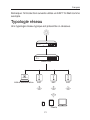
Τοπολογία δικτύου
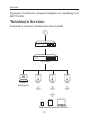
Ακολουθεί η συνήθης τοπολογία δικτύου του EAP.
Omada Controller
Router
PoE Switch
Συσκευή
διαχείρισης
EAP EAP EAP
Συνδεδεμένες συσκευές (Clients)

17
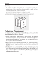
Eλληνικά
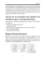
Το EAP μπορεί να τροφοδοτηθεί μόνο μέσω συσκευής PSE,
όπως PoE switch. Ένας DHCP server (συνήθως ένα router)
απαιτείται για την ανάθεση διευθύνσεων IP στα EAP και στις
συνδεδεμένες συσκευές (clients) στο τοπικό δίκτυό σας. Η
συσκευή διαχείρισης (host) μπορεί να βρίσκεται στο ίδιο ή σε
διαφορετικό υποδίκτυο από τα EAP.
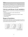
Λίστα με τα στοιχεία που πρέπει να
ελέγξετε πριν την εγκατάσταση
Πριν από την εγκατάσταση, βεβαιωθείτε ότι έχετε τα ακόλουθα
αντικείμενα:
• Ένα κουτί επιτοίχιο ή χωνευτό
• Ένα βύσμα RJ45
• Ένα τριγωνικό κατσαβίδι (Μόνο για το EAP115-Wall)
• Ένα σταυροκατσάβιδο
• Ένας κατανεμητής PoE
Βήματα Εγκατάστασης
Μπορείτε να συνδέσετε το EAP είτε σε κουτί 86χιλ. είτε σε
απλό επιτοίχιο κουτί Ευρωπαϊκών προδιαγραφών. Το κουτί
πρέπει να είναι είδη εγκατεστημένο μέσα στον τοίχο και να
υπάρχει ένα καλώδιο Ethernet που να περνά μέσα από τον
τοίχο και να είναι συνδεδεμένο σε PoE switch.
Κουτί σύνδεσης
τοίχου 86χιλ
.
Απλό κουτί
σύνδεσης της ΕΕ
Πρότυπο αμερικάνικο
χωνευτό κουτί τοίχου (Μόνο
για το EAP225-Wall

18
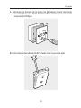
Eλληνικά
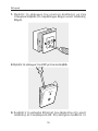
1. Βγάλτε το κάλυμμα του κουτιού σύνδεσης με ένα
σταυροκατσάβιδο (το παράδειγμα δείχνει κουτί σύνδεσης
86χιλ.).
2. Βγάλτε το κάλυμμα του EAP με ένα κατσαβίδι.
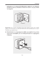
3. Συνδέστε το καλώδιο Ethernet που βρίσκεται στο κουτί
σύνδεσης σε ένα βύσμα RJ45. Στη συνέχεια συνδέστε το
Seite wird geladen ...
Seite wird geladen ...
Seite wird geladen ...
Seite wird geladen ...
Seite wird geladen ...
Seite wird geladen ...
Seite wird geladen ...
Seite wird geladen ...
Seite wird geladen ...
Seite wird geladen ...
Seite wird geladen ...
Seite wird geladen ...
Seite wird geladen ...
Seite wird geladen ...
Seite wird geladen ...
Seite wird geladen ...
Seite wird geladen ...
Seite wird geladen ...
Seite wird geladen ...
Seite wird geladen ...
Seite wird geladen ...
Seite wird geladen ...
Seite wird geladen ...
Seite wird geladen ...
Seite wird geladen ...
Seite wird geladen ...
Seite wird geladen ...
Seite wird geladen ...
Seite wird geladen ...
Seite wird geladen ...
Seite wird geladen ...
Seite wird geladen ...
Seite wird geladen ...
Seite wird geladen ...
Seite wird geladen ...
Seite wird geladen ...
Seite wird geladen ...
Seite wird geladen ...
Seite wird geladen ...
Seite wird geladen ...
Seite wird geladen ...
Seite wird geladen ...
Seite wird geladen ...
Seite wird geladen ...
Seite wird geladen ...
Seite wird geladen ...
Seite wird geladen ...
Seite wird geladen ...
Seite wird geladen ...
Seite wird geladen ...
Seite wird geladen ...
Seite wird geladen ...
Seite wird geladen ...
Seite wird geladen ...
Seite wird geladen ...
Seite wird geladen ...
-
 1
1
-
 2
2
-
 3
3
-
 4
4
-
 5
5
-
 6
6
-
 7
7
-
 8
8
-
 9
9
-
 10
10
-
 11
11
-
 12
12
-
 13
13
-
 14
14
-
 15
15
-
 16
16
-
 17
17
-
 18
18
-
 19
19
-
 20
20
-
 21
21
-
 22
22
-
 23
23
-
 24
24
-
 25
25
-
 26
26
-
 27
27
-
 28
28
-
 29
29
-
 30
30
-
 31
31
-
 32
32
-
 33
33
-
 34
34
-
 35
35
-
 36
36
-
 37
37
-
 38
38
-
 39
39
-
 40
40
-
 41
41
-
 42
42
-
 43
43
-
 44
44
-
 45
45
-
 46
46
-
 47
47
-
 48
48
-
 49
49
-
 50
50
-
 51
51
-
 52
52
-
 53
53
-
 54
54
-
 55
55
-
 56
56
-
 57
57
-
 58
58
-
 59
59
-
 60
60
-
 61
61
-
 62
62
-
 63
63
-
 64
64
-
 65
65
-
 66
66
-
 67
67
-
 68
68
-
 69
69
-
 70
70
-
 71
71
-
 72
72
-
 73
73
-
 74
74
-
 75
75
-
 76
76


TP-LINK Auranet EAP115 Bedienungsanleitung
- Typ
- Bedienungsanleitung
- Dieses Handbuch eignet sich auch für
in anderen Sprachen
- français: TP-LINK Auranet EAP115 Le manuel du propriétaire
- italiano: TP-LINK Auranet EAP115 Manuale del proprietario
- Nederlands: TP-LINK Auranet EAP115 de handleiding
- português: TP-LINK Auranet EAP115 Manual do proprietário
- dansk: TP-LINK Auranet EAP115 Brugervejledning
- svenska: TP-LINK Auranet EAP115 Bruksanvisning
Verwandte Artikel
Andere Dokumente
-
Digi Connect W Benutzerhandbuch
-
Pelco Sarix Professional IWP 2 Wedge Benutzerhandbuch
-
Dell PowerConnect 3448 Benutzerhandbuch
-
Axis 211W Installationsanleitung
-
Netatmo NOC01 Bedienungsanleitung
-
EverFocus EPOE16 Bedienungsanleitung
-
Trendnet TEW-453APB Datenblatt
-
Netatmo NOC01-US Benutzerhandbuch
-