TP-LINK tp-link Outdoor Access Point Installationsanleitung
- Typ
- Installationsanleitung

Installation Guide
Outdoor Access Point

CONTENTS
Deutsch ���������������������������������������������������������������������������01
English ������������������������������������������������������������������������������05
Español ���������������������������������������������������������������������������� 09
Eλληνικά ��������������������������������������������������������������������������13
Français ���������������������������������������������������������������������������17
Italiano ������������������������������������������������������������������������������21
Português ����������������������������������������������������������������������� 25
Suomi��������������������������������������������������������������������������������29
Nederlands ���������������������������������������������������������������������33
Svenska ��������������������������������������������������������������������������� 37
Norsk ��������������������������������������������������������������������������������41
Dansk ��������������������������������������������������������������������������������45

Deutsch
1
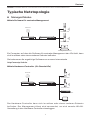
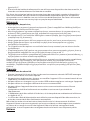
Hinweis: Die Bilder können vom tatsächlichen Aussehen des Produkts abweichen.
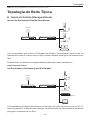
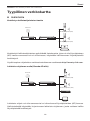
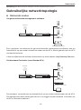
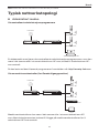
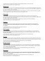
Typische Netztopologie
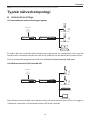
■Managed Modus
Mittels Software für zentrales Management
Management Software
Ein Computer, auf dem die Software für zentrales Management der APs läuft, kann
sich im selben oder einem anderen Subnetz benden.
Sie bekommen die zugehörige Software von unserer Internetseite
http://www.tp-link.de�
Mittels Hardware-Controller (für Omada APs)
Der Hardware-Controller kann sich im selben oder einem anderen Subnetz
befinden� Der Management-Host wird verwendet, um sich zwecks WLAN-
Verwaltung in den Hardware-Controller einzuloggen�
Router Switch
Internet
Management-Host
Outdoor-AP
Outdoor-AP
Router Switch
Internet
Outdoor-AP
Outdoor-AP
Hardware-Controller
Host

Deutsch
2
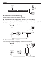
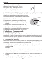
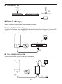
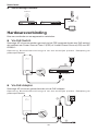
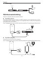
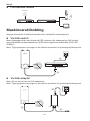
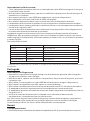
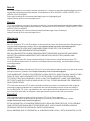
■Standalone-Modus
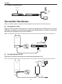
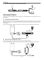
Hardwareverbindung
Wählen Sie eine Methode, Ihr Gerät zu verbinden�
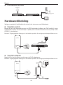
■Über einen PoE-Switch (nur bei APs mit 802.3af/at)
Einige APs können über das PSE-Gerät (z� B� einen PoE-Switch) mit Strom versorgt
werden, das der Stromquellenklasse 2 (PS2) oder der begrenzten Stromquelle (LPS) der
IEC 62368-1 entspricht�
Hinweis: Die Verfügbarkeit hängt von dem jeweiligen Produkt ab. Bitte beachten Sie die Produktspezikationen.
2
1
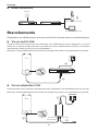
■Über einen PoE-Adapter
Einige APs können über den PoE-Adapter mit Strom versorgt werden�
Hinweis: Die Verfügbarkeit hängt von dem jeweiligen Produkt ab. Bitte beachten Sie die Produktspezikationen.
12
3
PoE-Switch
PoE LAN
Internet
Router
Host
Switch
Outdoor-AP

Deutsch
3
Oder
PoE LAN
1
2
3
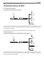
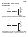
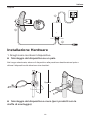
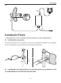
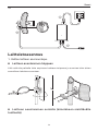
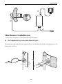
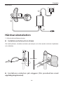
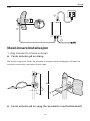
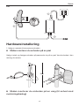
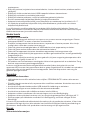
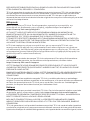
Hardwareinstallation
1� Wählen Sie eine Methode, Ihr Gerät zu installieren�
■Mastmontage
Bringen Sie das Gerät an geeigneter Stelle an den Mast an und richten Sie es grob
zur Gegenstelle aus�
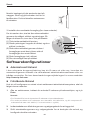
■Wandmontage (für Produkte mit Montagekit)
Oder

Deutsch
4
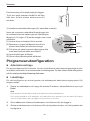
Montieren Sie das Montagekit an der
gewünschten Stelle an der Wand� Lassen
Sie das Gerät dort einrasten� Installieren
Sie dann die Antennen�
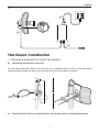
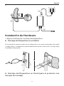
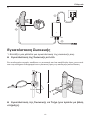
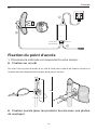
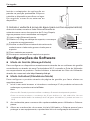
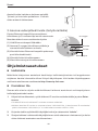
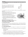
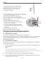
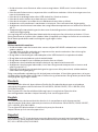
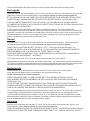
2� Installation der wasserdichten Kabeldurchführung� (nur für bestimmte Geräte)
Führen Sie das Ethernet-Kabel vor der Installation
durch die Spiralabdeckung, die Halterung und den
O-Ring� Befolgen Sie dann die in der Abbildung
gezeigten Schritte:
(1) Schließen Sie das Netzwerkkabel an den Port an�
(2) Befestigen Sie den O-Ring am Kopf der
Halterung und schrauben Sie die Halterung am
Gehäuse des Geräts fest�
(3) Führen Sie das Netzwerkkabel durch den Schlitz
der Dichtung mit der dickeren Seite in Richtung
der Halterung�
(4) Stecken Sie die Dichtung in die Halterung�
(5) Schrauben Sie die Spiralabdeckung an die
Halterung�
Spiralabdeckung
O-Ring
Dichtung
Halterung
1
2
3
4
5
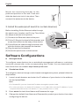
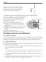
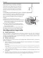
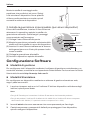
Softwarekonfiguration
■Managed Modus
Um eine große Anzahl Geräte mittels Managementsoftware oder WLAN-Controller
zu kongurieren, schauen Sie bitte im zugehörigen Handbuch nach. Dieses können
Sie von unserer Website http://www.tp-link.de herunterladen�
■Standalone-Modus
Um ein Gerät über die Weboberfläche zu konfigurieren, folgen Sie bitte diesen
Schritten�
1. Starten Sie Ihren Webbrowser und besuchen Sie die IP-Adresse Ihres Geräts�
Hinweis:
• Bei Omada APs können die IP-Adresse dem Produktetikett entnehmen.
• Für andere Produkte verwenden Sie bitte die Standard-IP-Adresse 192.168.0.254, wobei die
IP-Adresse Ihres Computers 192.168.0.x lauten muss (“x” steht hier für eine beliebige Zahl
von 1 bis 253).
2. Loggen Sie sich mit admin als Benutzername und Passwort ein�
3. Ändern Sie Benutzernamen und Passwort, um Ihr Gerät vor unbefugter
Benutzung zu schützen und starten Sie dann die Konguration.

English
5
Note: The image may dier from the actual product.
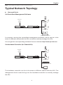
Typical Network Topology
■Managed Mode
Via Centralized Management Software
Management Software
A computer running the centralized management software, which can be in the
same or dierent subnet with the APs, is used to centrally manage the APs.
You can get the corresponding software from our website http://www.tp-link.com�
Via Hardware Controller (for Omada APs)
The hardware controller can be in the same or dierent subnet with the APs. The
management host is used to log in to the hardware controller to centrally manage
the APs�
Router Switch
Internet
Management Host
Outdoor AP
Outdoor AP
Router Switch
Internet
Outdoor AP
Outdoor AP
Hardware Controller
Host

English
6
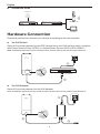
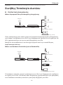
■Standalone Mode
Hardware Connection
Choose a method to connect your device according to the accessories.
■Via PoE Switch
Some APs can be powered via the PSE device (such as a PoE switch) which complies
with Power Source Class 2 (PS2) or Limited Power Source (LPS) of IEC 62368-1�
Note: Availability depends on the actual product. Please refer to the product specications.
2
1
■Via PoE Adapter
Some APs can be powered via the PoE adapter�
Note: Availability depends on the actual product. Please refer to the product specications.
12
3
PoE Switch
PoE LAN
Internet
Router
Host
Switch
Outdoor AP

English
7
Or
PoE LAN
1
2
3
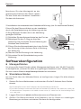
Hardware Installation
1� Choose a method to mount the device�
■Mounting the Device on a Pole
At the selected site, attach the device to a suitable point of the pole and then
approximately align the device to the direction that you have oriented.
Or
■Mounting the Device on the Wall (for the product with mounting brackets)

English
8
Mount the mounting bracket to the
preferred position in the wall� Push and
slide the device to lock it into place� Then
connect the antennas to the device�
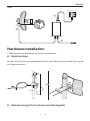
2� Install the waterproof seal� (For certain devices)
Before installing, t the Ethernet cable through
the spiral cover, bracket, and O-ring� Then follow
the steps as shown in the picture:
(1) Connect the Ethernet cable to the port�
(2) Fit the O-Ring to the head of the bracket, and
screw the bracket to the body of the device.
(3) Fit the Ethernet cable through the seal’s slit
with the thicker side towards the bracket�
(4) Plug the seal to the bracket�
(5) Screw the spiral cover to the bracket�
Spiral Cover
O-Ring
Seal
Bracket
1
2
3
4
5
Software Configurations
■Managed Mode
To configure mass devices via a centralized management software or a wireless
controller, please refer to the corresponding User Guide� You can download the
User Guide from our website http://www.tp-link.com�
■Standalone Mode
To congure a device through a web-based management system, please follow the
steps below�
1. Launch a web browser and enter the IP address of your device in the address
bar and press Enter�
Note:
• For Omada APs, you can check the IP address through the product label.
• For other products, the default IP address is 192.168.0.254 and the IP address of your
computer should be set as 192.168.0.x (“x” is any number from 1 to 253).
2. Enter admin for both User Name and Password for login�
3. Change the default User Name and Password to protect your device, then start
conguring the device.

Español
9
Nota: La imagen puede diferir del producto actual.
Topología Típica de Red
■Modo de Gestión
Vía Software de Gestión Centralizado
Management Software
Un ordenador funcionando con el software de gestión centralizado, el cual
puede estar en la misma o diferente subred que los APs, se utiliza para la gestión
centralizada de los APs�
Puede obtener el software correspondiente desde nuestra página web:
http://www.tp-link.es
A través del controlador de hardware (Para APs Omada)
El controlador de hardware puede estar en la misma o diferente subred que los APs,
la gestión del host se utiliza para acceder al controlador de hardware y gestionar
los APs de manera centralizada�
Router Switch
Internet
Host de Gestión
AP de Exterior
AP de Exterior
Router Switch
Internet
AP de Exterior
AP de Exterior
Controlador de hardware
Host

Español
10
■Modo Standalone
Conexión Hardware
Elija un método para conectar su dispositivo de acuerdo a los accesorios�
■Vía Switch PoE
Algunos APs pueden alimentarse a través del dispositivo PSE (como un switch
PoE) que cumple con la clase de fuente de alimentación 2 (PS2) o fuente de
alimentación limitada (LPS) de IEC 62368-1.
Nota: La disponibilidad depende del producto real. Consulte las especicaciones del producto.
2
1
■Vía Adaptador PoE
Algunos AP pueden alimentarse a través del adaptador PoE.
Nota: La disponibilidad depende del producto real. Consulte las especicaciones del producto.
12
3
Switch PoE
PoE LAN
Internet
Router
Host
Switch
AP de Exterior

Español
11
O
PoE LAN
1
2
3
Instalación de Hardware
1� Elija un método de montaje del dispositivo�
■Montaje del Dispositivo en un Mástil
En la ubicación seleccionada, una el dispositivo a un punto adecuado del mástil
y luego alinee el dispositivo aproximadamente hacia la dirección a la que haya
orientado el dispositivo�
■Montaje del Dispositivo en Pared (para el producto con
herrajes de montaje)
O

Español
12
Monte el herraje en la posición que
necesite en la pared. Apriete y deslice
el dispositivo hasta cerrarlo� Después,
conecte las antenas al dispositivo�
2� Instale el sello impermeable� (para ciertos dispositivos)
Antes de la instalación, coloque el cable Ethernet
a través de la cubierta en espiral, el soporte y
el aro de goma� Luego siga los pasos que se
muestran en la imagen:
(1) Conecte el cable Ethernet al puerto�
(2) Coloque el sello de goma en la cabeza del
soporte y atornille el soporte al cuerpo del
dispositivo�
(3) Coloque el cable Ethernet a través de la ranura
del sello con el lado más grueso hacia el
soporte�
(4) Conecte el sello al soporte�
(5) Atornille la cubierta en espiral al soporte�
Cubierta en espiral
Sello de goma
Sello
Soporte
1
2
3
4
5
Configuraciones de Software
■Modo de Gestión
Para congurar dispositivos de manera masiva a través del software centralizado
de gestión o desde el controlador inalámbrico, por favor diríjase a la Guía de
Usuario correspondiente� Puede descargar la Guía de Usuario de nuestra web�
■Modo Standalone
Para congurar un dispositivo a través del sistema de gestión basado en web, por
favor siga los siguientes pasos�
1. Inicie un navegador web e introduzca la dirección IP de su dispositivo en la
barra de direcciones y presione Intro�
Nota:
• En el caso de los AP Omada, puede comprobar la dirección IP a través de la etiqueta del producto.
• Para otros productos, la dirección IP por defecto es 192.168.0.254 y la dirección IP de su
ordenador debe estar congurada como 192.168.0.x (“x” es cualquer número entre 1 y 253).
2. Introduzca admin para iniciar sesión tanto en Nombre de Usuario como en
Contraseña�
3. Cambie el Nombre de Usuario y Contraseña por defecto para proteger su
dispositivo, después empiece a congurar el dispositivo.

Eλληνικά
13
Σημείωση: Οι εικόνες ενδέχεται να διαφέρουν από το πραγματικό προϊόν.
Συνήθης Τοπολογία Δικτύου
■ Κατάσταση Διαχείρισης
Μέσω Λογισμικού Κεντρικοποιημένης Διαχείρισης
Management Software
Ένας υπολογιστής στον οποίο τρέχει το λογισμικό κεντρικοποιημένης διαχείρισης,
που μπορεί να βρίσκεται στο ίδιο ή σε διαφορετικό υποδίκτυο σε σχέση με τα
APs, χρησιμοποιείται για την κεντρική διαχείριση των APs.
Μπορείτε να κατεβάσετε το αντίστοιχο λογισμικό από την ιστοσελίδα μας
http://www.tp-link.com�
Μέσω του Hardware Controller (για τα Omada APs)
Ο hardware controller μπορεί να βρίσκεται στο ίδιο ή σε διαφορετικό υποδίκτυο
σε σχέση με τα APs. Η συσκευή Host διαχείρισης χρησιμοποιείται για πρόσβαση
στον hardware controller με σκοπό τη κεντρική διαχείριση των APs.
Router Switch
Internet
Συσκευή διαχείρισης (Host)
AP Εξωτερικού Χώρου
AP Εξωτερικού Χώρου
Router Switch
Internet
AP Εξωτερικού Χώρου
AP Εξωτερικού Χώρου
Hardware Controller
Συσκευή διαχείρισης (Host)

Eλληνικά
14
■ Αυτόνομη Κατάσταση
Σύνδεση Συσκευής
Επιλέξτε μία μέθοδο για σύνδεση της συσκευής σας.
■ Μέσω PoE Switch
Ορισμένα APs μπορούν να τροφοδοτηθούν μέσω μίας συσκευής PSE (όπως ένα
PoE switch) που συμμορφώνεται με το πρότυπο Power Source Class 2 (PS2) ή το
Limited Power Source (LPS) του IEC 62368-1.
Σημείωση: Η διαθεσιμότητα εξαρτάται από το πραγματικό προϊόν. Παρακαλώ ανατρέξτε στις
προδιαγραφές του προϊόντος.
2
1
■ Μέσω Προσαρμογέα PoE
Ορισμένα AP μπορούν να τροφοδοτηθούν μέσω του προσαρμογέα PoE.
Σημείωση: Η διαθεσιμότητα εξαρτάται από το πραγματικό προϊόν. Παρακαλώ ανατρέξτε στις
προδιαγραφές του προϊόντος.
12
3
PoE Switch
PoE LAN
Internet
Router
Συσκευή διαχείρισης (Host)
Switch
AP Εξωτερικού Χώρου

Eλληνικά
15
ή
PoE LAN
1
2
3
Εγκατάσταση Συσκευής
1. Επιλέξτε μία μέθοδο για εγκατάσταση της συσκευής σας.
■ Εγκατάσταση της Συσκευής σε Ιστό
Στο επιλεγμένο σημείο, συνδέστε τη συσκευή σε ένα κατάλληλο ύψος στον ιστό
και στη συνέχεια ευθυγραμμίστε τη συσκευή προς την επιθυμητή κατεύθυνση.
■Εγκατάσταση της Συσκευής σε Τοίχο (για προϊόν με βάση
στήριξης)
ή

Eλληνικά
16
Εγκαταστήστε τη βάση στήριξης στην
επιθυμητή θέση στον τοίχο. Πιέστε
και σύρετε μέσα τη συσκευή για να
ασφαλίσει στη θέση της. Στη συνέχεια
συνδέσετε τις κεραίες στη συσκευή.
2. Τοποθέτηση της αδιάβροχης μόνωσης. (για ορισμένες συσκευές)
Πριν την τοποθέτηση, περάστε το καλώδιο Ethernet
μέσα από το σπειροειδές κάλυμμα, τη ροζέτα και το
δακτύλιο. Στη συνέχεια, ακολουθήστε τα βήματα όπως
φαίνεται στην εικόνα:
(1) Συνδέστε το καλώδιο Ethernet στη θύρα.
(2) Προσαρμόστε το δακτύλιο στην κεφαλή της
ροζέτας και βιδώστε τη ροζέτα στο σώμα της
συσκευής.
(3) Προσαρμόστε το καλώδιο Ethernet μέσω της
σχισμής του στεγανοποιητικού υλικού σε αυτό με
την παχύτερη πλευρά προς τη ροζέτα.
(4) Εφαρμόστε το στεγανοποιητικό υλικό στη ροζέτα.
(5) Βιδώστε το σπειροειδές κάλυμμα στη ροζέτα.
Σπειροειδές
κάλυμμα
Δακτύλιος
Στεγανοποιητικό
υλικό
Ροζέτα
1
2
3
4
5
Ρυθμίσεις Λογισμικού
■ Κατάσταση Διαχείρισης
Για τη μαζική ρύθμιση συσκευών μέσω του λογισμικού κεντρικοποιημένης
διαχείρισης ή μέσω ενός ασύρματου ελεγκτή, παρακαλούμε ανατρέξτε στις
αντίστοιχες Οδηγίες Χρήσης. Μπορείτε να κατεβάσετε τις Οδηγίες Χρήσης από
τον ιστότοπό μας http://www.tp-link.com�
■ Αυτόνομη Κατάσταση
Για να ρυθμίσετε κάποια συσκευή μέσω του συστήματος διαχείρισης μέσω
ιστοσελίδας, παρακαλούμε ακολουθήστε τα εξής βήματα.
1. Ανοίξτε κάποιο web browser (πρόγραμμα περιήγησης ιστού) και
πληκτρολογήστε τη διεύθυνση IP της συσκευής σας στη μπάρα διευθύνσεων
και πιέστε Enter�
Σημείωση:
• Για τα Omada APs, μπορείτε να ελέγξετε τη διεύθυνση IP μέσω της ετικέτας του προϊόντος.
• Για άλλα προϊόντα, η εργοστασιακή διεύθυνση IP είναι η 192.168.0.254 και η διεύθυνση
IP του υπολογιστή σας θα πρέπει να είναι της μορφής 192.168.0.x (όπου “x” είναι ένας
αριθμός από 1 έως 253).
2. Πληκτρολογήστε admin και ως Όνομα Χρήστη και ως Κωδικό Πρόσβασης για
είσοδο.
3. Αλλάξτε το εργοστασιακό Όνομα Χρήστη και Κωδικό για να προστατεύσετε
τη συσκευή σας και στη συνέχεια ξεκινήστε να τη ρυθμίζετε.

Français
17
Remarque: L’aspect des illustrations peut diérer de celui du produit réel.
Topologie d’un réseau typique
■Mode administré
Via le logiciel d’administration centralisé
Management Software
Un ordinateur exécutant le logiciel d’administration centralisé, qui peut être dans le
même sous-réseau ou non que celui des points d’accès, est utilisé pour administrer
de manière centralisée les PA (Point d’Accès)�
Vous pouvez obtenir le logiciel d’aministration depuis : http://www.tp-link.fr�
Via Contrôleur Matériel (pour les points d’accès Omada)
Le contrôleur matériel peut être dans le même sous-réseau ou Wi-Fi points d’accès�
L’hôte d’administration est utilisé pour se connecter au contrôleur matériel pour
administrer centralement les PA (Point d’Accès)�
Routeur Switch
Internet
Hôte d’administration
Point d’accès externe
Point d’accès externe
Routeur Switch
Internet
Point d’accès externe
Point d’accès externe
Contrôleur Matériel
Hôte d’administration

Français
18
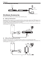
■Mode autonome
Branchements
Choisissez une méthode pour brancher votre PA en fonction de ses caractéristiques�
■Via un switch PoE
Certains points d’accès peuvent être alimentés via un PSE (Power Source Equipment : tel qu’un
switch ou un injecteur PoE) conforme à la classe de source d’alimentation 2 (PS2) ou à la source
d’alimentation limitée (LPS) de la norme CEI 62368-1�
Remarque : la disponibilité dépend du produit réel. Veuillez vous référer aux spécications du produit.
2
1
■Via un adaptateur PoE
Certains points d’accès peuvent être alimentés via un adaptateur PoE spécique (fourni en ce cas).
Remarque : la disponibilité dépend du produit réel. Veuillez vous référer aux spécications du produit.
12
3
Switch PoE
Données +
Alimentation
Données
Internet
Routeur
Hôte d’administration
Switch
Point d’accès externe
Seite wird geladen ...
Seite wird geladen ...
Seite wird geladen ...
Seite wird geladen ...
Seite wird geladen ...
Seite wird geladen ...
Seite wird geladen ...
Seite wird geladen ...
Seite wird geladen ...
Seite wird geladen ...
Seite wird geladen ...
Seite wird geladen ...
Seite wird geladen ...
Seite wird geladen ...
Seite wird geladen ...
Seite wird geladen ...
Seite wird geladen ...
Seite wird geladen ...
Seite wird geladen ...
Seite wird geladen ...
Seite wird geladen ...
Seite wird geladen ...
Seite wird geladen ...
Seite wird geladen ...
Seite wird geladen ...
Seite wird geladen ...
Seite wird geladen ...
Seite wird geladen ...
Seite wird geladen ...
Seite wird geladen ...
Seite wird geladen ...
Seite wird geladen ...
Seite wird geladen ...
Seite wird geladen ...
Seite wird geladen ...
Seite wird geladen ...
Seite wird geladen ...
Seite wird geladen ...
Seite wird geladen ...
Seite wird geladen ...
-
 1
1
-
 2
2
-
 3
3
-
 4
4
-
 5
5
-
 6
6
-
 7
7
-
 8
8
-
 9
9
-
 10
10
-
 11
11
-
 12
12
-
 13
13
-
 14
14
-
 15
15
-
 16
16
-
 17
17
-
 18
18
-
 19
19
-
 20
20
-
 21
21
-
 22
22
-
 23
23
-
 24
24
-
 25
25
-
 26
26
-
 27
27
-
 28
28
-
 29
29
-
 30
30
-
 31
31
-
 32
32
-
 33
33
-
 34
34
-
 35
35
-
 36
36
-
 37
37
-
 38
38
-
 39
39
-
 40
40
-
 41
41
-
 42
42
-
 43
43
-
 44
44
-
 45
45
-
 46
46
-
 47
47
-
 48
48
-
 49
49
-
 50
50
-
 51
51
-
 52
52
-
 53
53
-
 54
54
-
 55
55
-
 56
56
-
 57
57
-
 58
58
-
 59
59
-
 60
60


TP-LINK tp-link Outdoor Access Point Installationsanleitung
- Typ
- Installationsanleitung
in anderen Sprachen
- italiano: TP-LINK tp-link Outdoor Access Point Guida d'installazione
- Nederlands: TP-LINK tp-link Outdoor Access Point Installatie gids
- português: TP-LINK tp-link Outdoor Access Point Guia de instalação
- dansk: TP-LINK tp-link Outdoor Access Point Installationsvejledning
- svenska: TP-LINK tp-link Outdoor Access Point Installationsguide
Verwandte Artikel
-
TP-LINK Auranet EAP115 Bedienungsanleitung
-
TP-LINK EAP245 AC1750 V3 WHITE Benutzerhandbuch
-
TP-LINK TL-WA5210G V2 Bedienungsanleitung
-
TP-LINK tp-link Archer VR2100 Wireless DSL Modem Router Installationsanleitung
-
-
-
TP-LINK M7450 Benutzerhandbuch
-