
Installationsanleitung
Optionen-Steuerset SSM230/SSM400
V-ZUG AG
Industriestrasse 66, Postfach 59, 6301 Zug
T
elefon 041 767 67 67, Fax 041 767 62 60
vzug@vzug.ch, www.vzug.ch
P60.008D-5
erstellt
0
9.12.2009 BEU
geändert
1
0.08.2012 BEU
1
geprüft
10.08.2012 BEU
1 / 22
p60_008d-5.doc gedruckt
05.09.2012
English version from page 12.
Inhalt
1 Varianten von Optionen-Steuersets...............................................................................................2
1.1 Einzelne Bestandteile........................................................................................................................2
1.2 Optionen-Steuersets..........................................................................................................................2
1.3 Abmessungen....................................................................................................................................3
2 Funktionsbeschreibung / Einsatzmöglichkeiten...........................................................................4
3 Anwendungsbeispiele.....................................................................................................................5
3.1 Beispiel 1: Ein einzelnes Gerät steuert eine einzelne Zusatzeinrichtung (Standardsituation).............5
3.2 Beispiel 2: Mehrere Geräte steuern eine einzelne Zusatzeinrichtung.................................................5
3.3 Beispiel 3: Ein einzelnes Gerät steuert mehrere Zusatzeinrichtungen...............................................5
3.4 Beispiel 4: Mehrere Geräte steuern mehrere Zusatzeinrichtungen (Extremsituation) ........................6
4 Installation .......................................................................................................................................7
4.1 Installation Stromsensor-Modul SSM1 mit einem Stromsensor für max. 16A ....................................7
4.2 Installation Stromsensor-Modul SSM2 mit zwei Stromsensoren für max. 25A...................................7
4.3 Installation Stromsensor-Set SSE für Einbau in V-ZUG-Geräte.........................................................8
4.4 Installation Relaismodul RM ..............................................................................................................8
4.5 Anforderungen an das Steuerkabel...................................................................................................8
5 Anschluss und Einstellung des Relaismoduls..............................................................................9
5.1 Anschluss eines Stromsensors und Einstellung der Einschaltschwelle..............................................9
5.2 Anschluss einer Spannungsquelle und Einstellung der Einschaltschwelle.........................................9
5.3 Anschluss eines potentialfreien Schalters........................................................................................10
5.4 Verhinderung des Relais-Taktens bei vorübergehenden Lücken im Stromfluss ..............................10
5.5 Invertierung der Relaisfunktion........................................................................................................10
5.6 Steuern von Zusatzeinrichtungen mittels potentialfreiem Relaiskontakt...........................................10
6 Fragenkatalog zur Planung...........................................................................................................11
Das Optionen-Steuerset dient zur Steuerung fremder Geräte durch ein Steuersignal, das von einem ZUG-
Gerät erzeugt wird. Für ein einwandfreies Zusammenspiel müssen die elektrischen Eigenschaften der bei-
den Bestandteile bekannt sein. Eine sorgfältige Abklärung ist notwendig und setzt elektrotechnische Fach-
kenntnisse voraus.
Die Planung und Installation ist deshalb elektrotechnischem Fachpersonal vorbehalten.

Installationsanleitung
Optionen-Steuerset SSM230/SSM400
V-ZUG AG
Industriestrasse 66, Postfach 59, 6301 Zug
T
elefon 041 767 67 67, Fax 041 767 62 60
vzug@vzug.ch, www.vzug.ch
P60.008D-5
erstellt
0
9.12.2009 BEU
geändert
1
0.08.2012 BEU
1
geprüft
10.08.2012 BEU
2 / 22
p60_008d-5.doc gedruckt
05.09.2012
1 Varianten von Optionen-Steuersets
1.1 Einzelne Bestandteile
Stromsensor-Modul SSM1 mit 1 Stromsensor für max. 16A P60.031
zum Einfügen in die Zuleitung von V-ZUG-Geräten mit Anschlussart 230V~ / 400V2~
Stromsensor-Modul SSM2 mit 2 Stromsensoren für max. 25A P60.032
zum Einfügen in die Zuleitung von V-ZUG-Geräten mit Anschlussart 400V2N~ / 400V3N~ / 400V3~
Stromsensor-Set SSE P60.035
für Einbau in V-ZUG-Geräte
Relaismodul kpl. RM P60.033
zum Steuern einer Zusatzeinrichtung
1.2 Optionen-Steuersets
Die einzelnen Bestandteile sind auch als Set erhältlich
Optionen-Steuerset SSM230 P60.036
bestehend aus: 1 Stromsensor-Modul SSM1 und 1 Relaismodul kpl. RM
Optionen-Steuerset SSM400 P60.037
bestehend aus: 1 Stromsensor-Modul SSM2 und 1 Relaismodul kpl. RM

Installationsanleitung
Optionen-Steuerset SSM230/SSM400
V-ZUG AG
Industriestrasse 66, Postfach 59, 6301 Zug
T
elefon 041 767 67 67, Fax 041 767 62 60
vzug@vzug.ch, www.vzug.ch
P60.008D-5
erstellt
0
9.12.2009 BEU
geändert
1
0.08.2012 BEU
1
geprüft
10.08.2012 BEU
3 / 22
p60_008d-5.doc gedruckt
05.09.2012
1.3 Abmessungen
Stromsensor-Modul SSM1
(Gehäuse ohne Kabelverschraubungen gezeichnet, M1:2)
Relaismodul kpl. RM / Stromsensor-Modul SSM2
(Gehäuse ohne Kabelverschraubungen gezeichnet, M1:2)
Stromsensor SSE für Einbau in V-ZUG-Geräte
(M1:1)
50
0
5
5
0
45
25
20
Ø4
max. 15
Überstand
max. 3

Installationsanleitung
Optionen-Steuerset SSM230/SSM400
V-ZUG AG
Industriestrasse 66, Postfach 59, 6301 Zug
T
elefon 041 767 67 67, Fax 041 767 62 60
vzug@vzug.ch, www.vzug.ch
P60.008D-5
erstellt
0
9.12.2009 BEU
geändert
1
0.08.2012 BEU
1
geprüft
10.08.2012 BEU
4 / 22
p60_008d-5.doc gedruckt
05.09.2012
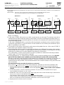
2 Funktionsbeschreibung / Einsatzmöglichkeiten
Das Optionen-Steuerset besteht aus 2 Bestandteilen:
e
inem Stromsensor (in 3 Varianten erhältlich) und
dem Relaismodul als Steuereinheit.
Die beiden Bestandteile werden mit einem Steuerkabel miteinander verbunden.
Der Stromsensor misst den Aufnahmestrom des V-ZUG-Gerätes und meldet diesen über das Steu-
erkabel dem Relaismodul. Sobald der Strombezug des V-ZUG-Gerätes eine gewisse Grenze über-
schreitet, schaltet das Relaismodul die Zusatzeinrichtung ein. Geeignet als befehlsgebende Geräte
sind V-ZUG-Geräte mit Anschlussart 230V~ oder 400V~.
Der Stromsensor wird in die Zuleitung des V-ZUG-Gerätes eingefügt, das Relaismodul in die Zulei-
tung der zu steuernden Zusatzeinrichtung.
Falls im Einzelfall der Stromfluss in der Gerätezuleitung nicht eindeutig zur Steuerung einer Zusatz-
einrichtung geeignet ist, besteht die Möglichkeit, einen Stromsensor in das V-ZUG-Gerät einzubau-
en. Damit kann der Strombezug eines einzelnen geräteinternen Verbrauchers erfasst und als Steu-
ersignal für die Zusatzeinrichtung heran gezogen werden. In diesem Fall ist ein Eingriff ins Gerät nö-
tig und der Sensoreinbau muss durch die V-ZUG AG erfolgen (im Werk oder vor Ort durch den
V-ZUG-Fullservice). Diese Möglichkeit ist z.B. hilfreich bei Ansteuerung einer Motorklappe ab
Dunstabzug, bei dem das Einschalten des Lichts bereits zum Öffnen der Motorklappe führen würde.
Der Sensor wird so ins Gerät eingebaut, dass er nur den Stromfluss des Lüfters erfasst und nicht
auch noch jenen der Beleuchtung.
Je nach Schalterstellung auf dem Relaismodul und der Anzahl Windungen auf dem Stromsensor
kann die Einschaltschwelle des Relais auf verschiedene Werte gesetzt werden. Ebenfalls einstellbar
ist eine Relais-Ausschaltverzögerung ("Nachlauf"). Diese kann dazu benutzt werden, dass auch bei
lückenhaftem Strombezug des Befehlsgebers (z.B. bei getaktet angesteuerten Heizungen im Koch-
feld) die Zusatzeinrichtung (z.B. Raumbelüfter) trotzdem unterbruchsfrei angesteuert bleibt. Weitere
Details siehe Kap. 5.
Das Relaismodul kann auch mit Signalen ab einer Spannungsquelle (z.B. Elektronik-Baugruppe)
oder ab potentialfreiem Kontakt angesteuert werden. Weitere Details siehe Kap. 5.
Durch die universelle Auslegung der Module lassen sich auch komplexere, verschachtelte Steue-
rungen realisieren. Dank der galvanisch vom Netz getrennten Steuerleitung (Isolation der Schutz-
klasse II / 4kV) ist die Ansteuerung verschiedenster Zusatzeinrichtungen möglich, die alle an ver-
schiedenen Sicherungsgruppen liegen dürfen. Weitere Details siehe Beispiele im Kap. 3.
Der Einbau der Module erfolgt als Bestandteil der Hausinstallation. Jedes Modul ist in ein eigenes
Gehäuse eingebaut. Dies gewährleistet die Erfüllung der gesetzlichen Vorschrift, dass pro Gerät nur
Netzspannung ab einer einzigen Sicherungsgruppe zugeführt werden darf.
Alle Module sind SEV-geprüft und tragen das
-Sicherheitszeichen.
Netzzuleitung für
V-ZUG-Gerät
Relaismodul
(Steuereinheit)
befehlsgebendes Gerät
Stromsensor
Isolation 4kV
(Schutzklasse II)
Isolation 4kV
(Schutzklasse II)
externe
Zusatzeinrichtung
(z.B. Motorklappe)
V-ZUG-Gerät
bzw. geräteinterner
Verbraucher
(z.B. Lüfter)
I
1
2
Steuerkabel
(nur Schutz
-
Kleinspannung enthaltend)
Netzzuleitung für Relais-
Modul und Zusatzeinrichtung
230V~
2
30V~
12V-
b a L N
L N
1
2
3
4
5
befehlsempfangendes Gerät

Installationsanleitung
Optionen-Steuerset SSM230/SSM400
V-ZUG AG
Industriestrasse 66, Postfach 59, 6301 Zug
T
elefon 041 767 67 67, Fax 041 767 62 60
vzug@vzug.ch, www.vzug.ch
P60.008D-5
erstellt
0
9.12.2009 BEU
geändert
1
0.08.2012 BEU
1
geprüft
10.08.2012 BEU
5 / 22
p60_008d-5.doc gedruckt
05.09.2012
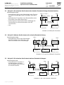
3 Anwendungsbeispiele
3.1 Beispiel 1: Ein einzelnes Gerät steuert eine einzelne Zusatzeinrichtung (Standardsituation)
Anwendungsbeispiele:
− Automatisches Öffnen einer Motorklappe oder Einschal-
ten eines Dunstabzuges beim Einschalten eines Back-
ofens.
− Automatisches Einschalten eines Raumbelüfters beim
Einschalten eines Wäschetrockners
− Steuerung eines Kassierzeitschalters abhängig vom
Strombezug eines Waschautomaten oder Wä-
schetrockners
− usw.
3.2 Beispiel 2: Mehrere Geräte steuern eine einzelne Zusatzeinrichtung
Anwendungsbeispiele:
− Automatisches Öffnen einer Motorklappe
beim Einschalten eines Backofens und
beim Einschalten eines Dunstabzuges.
3.3 Beispiel 3: Ein einzelnes Gerät steuert mehrere Zusatzeinrichtungen
Anwendungsbeispiel:
− Automatisches Einschalten ei-
ner Motorklappe und eines
Dachventilators beim Einschal-
ten eines Backofens.
400V~ (ev. 230V~)
SSM2 (ev. SSM1)
2 1 2 1
Backofen /
Wäschetrockner
RM
1 2 3 4 5
230V~
Motorklappe /
Raumbelüfter
Z
usatzeinricht. (Empf.)
G
erät (Sender)
1)
Steuersignal
Steuersignal
400V~
SSM2
2 1 2 1
SSM1
2 1
4)
1)
230V~
Dunstabzug
230V~
Backofen
400V3~
2)
RM
1 2 3 4 5
230V~
Motorklappe
230V~
Zusatzeinricht. (Empf.)
Gerät 1 (Sender 1)
Gerät 2 (Sender 2)
Steuersignal Zusatzeinr. 1
400V~
SSM2
2 1 2 1
1)
Backofen
400V3~
Gerät (Sender)
1 2
RM
3)
230V~
1 2 3 4 5
Dachventilator
230V~
Zusatzeinricht. 2 (Empf. 2)
RM
1 2 3 4
5
230V~
Motorklappe
230V~
Zusatzeinricht. 1 (Empf. 1)
Steuersignal Zusatzeinr. 2
Hinweis 1) bei Beispiel 4 beachten
Hinweise 1), 2) und 4) bei Beispiel 4 beachten
Hinweise 1) und 3) bei Beispie
l 4 beachten

Installationsanleitung
Optionen-Steuerset SSM230/SSM400
V-ZUG AG
Industriestrasse 66, Postfach 59, 6301 Zug
T
elefon 041 767 67 67, Fax 041 767 62 60
vzug@vzug.ch, www.vzug.ch
P60.008D-5
erstellt
0
9.12.2009 BEU
geändert
1
0.08.2012 BEU
1
geprüft
10.08.2012 BEU
6 / 22
p60_008d-5.doc gedruckt
05.09.2012
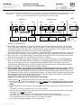
3.4 Beispiel 4: Mehrere Geräte steuern mehrere Zusatzeinrichtungen (Extremsituation)
Beispiel: Gebäude mit mehreren Wohnungen mit je 1 Backofen, Dunstabzug und Motorklappe, pro Gebäude 1 Dachventilator
Steuerfunktion - sobald ein Backofen oder ein Dunstabzug eingeschaltet wird, öffnet die zugehörige Motorklappe
- sobald irgend eine Motorklappe öffnet, wird der Dachventilator eingeschaltet
Hinweise / Einsatzgrenzen
1) Beim SSM2 kann entweder nur einer oder beide Strom-Sensoren benutzt werden. Die Sensoren
sind in diejenigen Polleiter einzufügen, deren Stromfluss für die Steuerung der Zusatzeinrichtung
entscheidend sind. Wenn die interne Verdrahtung des angeschlossenen Geräts unbekannt ist, müs-
sen die massgeblichen Polleiter durch einen Test ermittelt werden.
Bei Geräten mit Anschluss von nur 2 Polleitern ohne Neutralleiter (Anschlussart 400V2~) ist nur bei
einem der beiden Polleiter ein Stromsensor einzufügen (bis 16A Verwendung von SSM1 möglich).
2) Die Anzahl aller in Serie geschalteten Sensoren darf nicht grösser als 6 sein. Werden beim SSM2
beide Sensoren benutzt, so sind diese als 2 Einheiten zu zählen.
3) Sind mehrere Zusatzeinrichtungen anzusteuern, die an unterschiedlichen Sicherungsgruppen lie-
gen, so sind mehrere Relais-Module vorzusehen. Das Ausgangssignal des ersten Relais-Moduls
kann auf die Eingänge von max. 6 weiteren Modulen geführt werden (Anschluss siehe oben).
Als alternative Möglichkeit kann ein Sensor-Signal auch parallel auf max. 2 Relaismodule geführt
werden (Eingänge 1-2 der Relais-Module parallel schalten).
4) Falls mehrere Geräte, d.h. mehrere Sensormodule eine Zusatzeinrichtung steuern sollen, so sind
die Ausgänge aller zugehörigen Sensormodule polaritätsrichtig in Serie zu schalten. Die Rich-
tigkeit der Polarität kann wegen der meist unbekannten Phasenverschiebung zwischen den einzel-
nen Polleitern nur durch einen Test festgestellt werden. Für eine korrekte Funktion muss die am Re-
laismodul gemessene Steuersignal-Spannung sich jedesmal vergrössern, sobald in irgend einem
der beteiligten Sensoren der Strom grösser wird.
Empfohlener Funktionstest nach dem Anschluss aller Module:
Hinweis: Werte in (..
) = gültig für Relaismodul-Ausführung P60.010-1, geliefert bis ca. Sept.05
1. Durch den ersten Sensor einen Strom von ca. 0.11A~ (0.25A~)
fliessen und während des ganzen Testab-
laufs eingeschaltet lassen (z.B. Glühlampe 25W (60W)
anschliessen). Alle übrigen Sensoren stromlos
halten.
2. Beim Relaismodul an den Klemmen 3-4 ein Voltmeter anschliessen (Messung des verstärkten Sensorsig-
nals).
Kontrollieren, ob sich eine Spannung von 1.3V~ ±0.3V einstellt.
3. Zusätzlich bei einem weiteren Sensor etwa denselben Strom wie beim ersten fliessen lassen (z.B. zweite
Glühlampe 25W (60W)
anschliessen).
Kontrollieren, ob sich die Spannung am Voltmeter um mindestens 50% vergrössert hat.
Falls nicht, sind an den Klemmen 1-2 des betreffenden Sensors die Anschlussdrähte zu vertauschen.
Nach erfolgreichem Test Strom bei diesem Sensor wieder abschalten.
4. Punkt 3 für alle weiteren beteiligten Sensoren wiederholen.
Wohnung 2
bis ...
Dach
Wohnung 1
Dachventilator
230V~
1
RM
230V~
1 2 3 4 5
400V~
SSM2
2 1 2 1
Steuersignal Zusatzeinr. 1 Steuersignal Zusatzeinr. 2
Steuersignal Zusatzeinr. x
SSM1
2 1
4)
1)
RM
1
2 3 4 5
230V~
230V~
400V~
SSM2
2
1 2 1
SSM1
2 1
4)
1)
RM
Backofen
400V3~
Dunstabzug
230V~
Motorklappe
230V~
1 2 3 4 5
3)
2
)
2)
230V~
230V~
Zusatzeinricht. 1 (
Empf. 1)
Gerät 1a (Sender 1a)
Gerät 1b (Sender 1b)
Zusatzeinricht. x (Empf. x)
Zusatzeinricht. 2 (Empf. 2)
Gerät 2a (Sender 2a)
Gerät 2b (Sender. 2b)
Backofen
400V3~
Dunstabzug
230V~
Motorklappe
230V~

Installationsanleitung
Optionen-Steuerset SSM230/SSM400
V-ZUG AG
Industriestrasse 66, Postfach 59, 6301 Zug
T
elefon 041 767 67 67, Fax 041 767 62 60
vzug@vzug.ch, www.vzug.ch
P60.008D-5
erstellt
0
9.12.2009 BEU
geändert
1
0.08.2012 BEU
1
geprüft
10.08.2012 BEU
7 / 22
p60_008d-5.doc gedruckt
05.09.2012
4 Installation
Allgemeiner Hinweis: Der Einbau der Module erfolgt als Bestandteil der Hausinstallation.
Der elektrische Anschluss ist durch fachkundiges Personal nach den Richtlinien und Normen
für Niederspannungsinstallationen und nach den Bestimmungen der örtlichen Elektrizitätswer-
ke auszuführen.
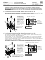
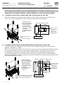
4.1 Installation Stromsensor-Modul SSM1 mit einem Stromsensor für max. 16A
Das Modul SSM1 wird in die Zuleitung von V-ZUG-Geräten eingefügt, die mit Anschlussart 230V~ oder
mit Anschlussart 400V2~ (2 Polleiter ohne Neutralleiter) angeschlossen werden.
4.2 Installation Stromsensor-Modul SSM2 mit zwei Stromsensoren für max. 25A
Das Modul SSM2 wird in die Zuleitung von V-ZUG-Geräten eingefügt, die mit Anschlussart 400V2N~
oder 400V3N~ oder 400V3~ angeschlossen werden.
Es kann entweder einer oder beide Stromsensoren benutzt werden. Die Sensoren sind in diejenigen
Polleiter einzufügen, deren Stromfluss für die Steuerung der Zusatzeinrichtung entscheidend sind.
Wenn die interne Verdrahtung des angeschlossenen Geräts unbekannt ist, müssen die massgeblichen
Polleiter durch einen Test ermittelt werden.
Bei Geräten mit Anschluss von nur 2 Polleitern ohne Neutralleiter (Anschlussart 400V2~) ist nur bei ei-
nem der beiden Polleiter ein Stromsensor einzufügen (bis 16A Verwendung von SSM1 möglich).
SSM1
1 2
1 2
N
etz 230V~ oder 400V2~
max. 16A~
2
1
Sender
V-ZUG-Gerät
Ausgang
Steuersignal
(ca 0.3V~/A~).
Galv. getrennt
(4kV) vom Netz.
Kabelverschraubungen
gemäss Abbildung
montieren.
Kabelverschraubungen gemäss Ab-
bildung mon
tieren. Für Kabel von Ø12
mm bis Ø16 mm sind beigelegte Stu-
fennippel zu verwenden.
N L1 L2 L3
N L1 L2 L3
2
1
2
1
SSM2
Netz 400V2N~ oder 400V3N~ oder 400V3~
max. 25A~
Sender
V-ZUG-Gerät
Ausgang
Steuersignal
(ca 0.3V~/A~).
Galv. getrennt
(4kV) vom Netz.
Falls am Stromsensor
ein Verbraucher mit
sehr kleinem Strombe-
zug angeschlossen ist,
kann die Ansprech-
empfindlichkeit durch
Erhöhung der Win-
dungszahl verbessert
werden.
Weitere Einzelheiten
und Einschränkungen
siehe Kap. 5.1.
Falls am Stromsensor
ein Verbraucher mit
sehr kleinem Strombe-
zug
angeschlossen ist,
kann die Ansprech-
empfindlichkeit durch
Erhöhung der Win-
dungszahl verbessert
werden.
Weitere Einzelheiten
und Einschränkungen
siehe Kap. 5.1.

Installationsanleitung
Optionen-Steuerset SSM230/SSM400
V-ZUG AG
Industriestrasse 66, Postfach 59, 6301 Zug
T
elefon 041 767 67 67, Fax 041 767 62 60
vzug@vzug.ch, www.vzug.ch
P60.008D-5
erstellt
0
9.12.2009 BEU
geändert
1
0.08.2012 BEU
1
geprüft
10.08.2012 BEU
8 / 22
p60_008d-5.doc gedruckt
05.09.2012
4.3 Installation Stromsensor-Set SSE für Einbau in V-ZUG-Geräte
Falls der Stromfluss in der Gerätezuleitung nicht eindeutig zur Steuerung einer Zusatzeinrichtung ge-
eignet ist, muss der Stromsensor in das V-ZUG-Gerät eingebaut werden. Damit kann der Strombezug
eines einzelnen geräteinternen Verbrauchers erfasst und als Steuersignal für die Zusatzeinrichtung
heran gezogen werden. In diesem Fall ist ein Eingriff ins Gerät nötig und der Sensoreinbau muss
deshalb durch die V-ZUG AG erfolgen (im Werk oder vor Ort durch den V-ZUG-Fullservice).
Diese Möglichkeit ist z.B. hilfreich bei Ansteuerung eines Raumbelüfters ab Dunstabzug, bei dem das
Einschalten des Lichts bereits zur Ansteuerung des Raumlüfters führen würde. Der Sensor wird so ins
Gerät eingebaut, dass er nur den Stromfluss des Lüfters erfasst und nicht auch noch jenen der Be-
leuchtung.
Weitere Einzelheiten zum Einbau sind der Installationsanleitung P60.028D zu entnehmen, die dem
Stromsensor-Set beigelegt ist.
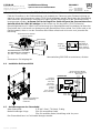
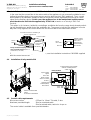
4.4 Installation Relaismodul RM
4.5 Anforderungen an das Steuerkabel
Ader-Querschnitt 0.35 bis 1.0mm² Td-Kabel, 2-adrig
Maximal zulässige Länge 20m für unverdrilltes Kabel
50m für verdrilltes Kabel, Verdrillung mind. 4x pro m
Das Steuerkabel kann im Fachhandel bezogen werden.
Eingang
Steuersignal
max. 30V
(ab Strom-
sensor oder
anderer
Quelle).
Galv. getrennt
(4kV) vom Netz
.
Empfänger
Zusatzeinrichtung
Speisung Relais-Modul
und ext. Zusatzeinrichtung
Netz 230V~
Relaismodul
230V~
12V-
W2 W1
b a L N
L N
1
2
3
4
5
max. 6A~ M
max. 10A~
R
4kV-Isol.
2
1
Eingang
max. 25A~
Ausgang
Steuersignal
(ca 0.3V~/A~).
Galv. getrennt
(4kV) vom Netz.
stromführenden Leiter über
den Stromsensor schlaufen!
(N- oder L-Leiter, nicht PE)
Stromsensor für Einbau
in V-ZUG-Geräte
Steuerkabel
Verbraucher
230V~ /
400V~
Kabelverschraubungen
gemäss Abbildung
montieren.

Installationsanleitung
Optionen-Steuerset SSM230/SSM400
V-ZUG AG
Industriestrasse 66, Postfach 59, 6301 Zug
T
elefon 041 767 67 67, Fax 041 767 62 60
vzug@vzug.ch, www.vzug.ch
P60.008D-5
erstellt
0
9.12.2009 BEU
geändert
1
0.08.2012 BEU
1
geprüft
10.08.2012 BEU
9 / 22
p60_008d-5.doc gedruckt
05.09.2012
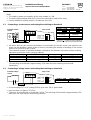
5 Anschluss und Einstellung des Relaismoduls
Hinweise
D
ie Standby-Leistungsaufnahme des Relaismoduls beträgt < 1W.
Die eingebaute Leuchtdiode zeigt den eingeschalteten Zustand des Relais an.
Werksvorgabe der Einstellwerte = alle Schalter nach links.
5.1 Anschluss eines Stromsensors und Einstellung der Einschaltschwelle
Falls am Stromsensor ein Verbraucher mit sehr kleinem Strombezug angeschlossen ist, kann die
Ansprechempfindlichkeit um Faktor 2 oder 3 erhöht werden, indem auf dem Stromsensor 2 oder 3
Windungen anstatt nur einer einzigen aufgebracht wird.
Die maximal mögliche Windungszahl ist begrenzt durch den Durchmesser des Drahtes und der dar-
aus resultierenden maximal zulässigen Strombelastbarkeit.
Anzahl Windungen Aussendurchmesser Querschnitt Strombelastbarkeit
1 (ab Werk) Litze max. 3.5mm max. 2.5mm² max. 25A~
2 Litze max. 2.2mm max. 1.0mm² max. 10A~
3 Litze max. 1.8mm max. 0.75mm² max. 6A~
Toleranz der Einschaltschwelle = ±20%.
Die Ausschaltschwelle liegt um ca. 15% tiefer als die Einschaltschwelle (Hysterese).
5.2 Anschluss einer Spannungsquelle und Einstellung der Einschaltschwelle
Als Eingangsspannung ist Gleich- oder Wechselspannung (50Hz) bis max. 30V zulässig
Eingangswiderstand = ca. 15kOhm
Toleranz der Einschaltschwelle = ±15%. Die Ausschaltschwelle liegt um ca. 15% tiefer als die Ein-
schaltschwelle (Hysterese)
externer
Stromsensor
2 1
LEVEL LOW HIGH
DELAY 0s 50s
DELAY 0s 220s
FUNC NORM INV
X3
1
2
3 4 5
1
2
3
4
→
ON
Relaismodul
externe
Spannungsquelle
LEVEL LOW HIGH
DELAY 0s 50s
DELAY 0s 220s
FUNC NORM INV
X3 1 2
3 4
5
1
2
3
4
→
ON
Relaismodul
Stromsensor 1 Windung (ab Werk)
LEVEL auf LOW LEVEL auf HIGH
0.1A~ (0.25A~) 0.2A~ (0.5A~)
Stromsensor
2 Windungen
Stromsensor
3 Windungen
LEVEL auf LOW LEVEL auf LOW
0.05A~ (0.1A~) 0.033A~ (0.08A~)
Werte in (..) = gültig für Ausführung
P60.010-1, geliefert bis ca. Sept.05
LEVEL auf LOW LEVEL auf HIGH
3V= oder 6V~ 6.5V= oder 13V~

Installationsanleitung
Optionen-Steuerset SSM230/SSM400
V-ZUG AG
Industriestrasse 66, Postfach 59, 6301 Zug
T
elefon 041 767 67 67, Fax 041 767 62 60
vzug@vzug.ch, www.vzug.ch
P60.008D-5
erstellt
0
9.12.2009 BEU
geändert
1
0.08.2012 BEU
1
geprüft
10.08.2012 BEU
10 / 22
p60_008d-5.doc gedruckt
05.09.2012
5.3 Anschluss eines potentialfreien Schalters
LEVEL-Schalter auf LOW stellen
Spannungsabfall über Schaltelement max. 1 V zulässig
Kontaktbelastung ca. 5V= / ca. 0.3mA
5.4 Verhinderung des Relais-Taktens bei vorübergehenden Lücken im Stromfluss
Mit den beiden DELAY-Schaltern kann bestimmt werden, wie lange das Relais noch angezogen
bleiben soll, nachdem der Stromsensor keinen Stromfluss mehr erkennt. Durch diese Relais-
Ausschaltverzögerung kann bei vorübergehenden Stromlücken ein unerwünschtes Takten des Re-
lais und demzufolge der Zusatzeinrichtung verhindert werden.
Diese Möglichkeit ist hilfreich z.B. bei Steuerung eines Raumlüfters ab taktendem Kochfeld.
Toleranz der Verzögerungszeiten = ±20%.
5.5 Invertierung der Relaisfunktion
Mit dem FUNC-Schalter kann die Relaisfunktion invertiert werden, sodass das Relais bei grösser
werdendem Eingangssignal abfällt, anstatt anzieht. Die Ausschaltverzögerung wirkt in diesem Fall
als Einschaltverzögerung.
5.6 Steuern von Zusatzeinrichtungen mittels potentialfreiem Relaiskontakt
Durch vollständiges Herausschneiden der Drahtbrücken W1 und
W2 kann die Zuführung von Netzspannung auf den Relaiskontakt
unterbrochen und damit potentialfrei gemacht werden.
Nicht zulässig ist die Anspeisung des Kontaktes mit Netzspannung
ab einer separaten Sicherungsgruppe.
externer potential
-
freier Schalter
oder
+
LEVEL LOW HIGH
DELAY 0s 50s
DELAY 0s 220s
FUNC NORM INV
X
3 1
2
3
4
5
1
2
3
4
→
ON
R
elaismodul
LEVEL LOW HIGH
DELAY 0s 50s
D
ELAY 0s 220s
FUNC NORM INV
X3 1 2 3 4 5
1
2
3
4
→
ON
Relaismodul
LEVEL LOW HIGH
DELAY 0s 50s
DELAY 0s 220s
FUNC NORM INV
X3 1 2 3 4 5
1
2
3
4
→
ON
Relaismodul
oberer DELAY-Schalter
0s 50s
unterer DELAY-Schalter
0s 220s
beide DELAY-Schalter ON
50s+220s = 270s
FUNC auf NORM FUNC auf INV
keine Inversion Inversion

Installationsanleitung
Optionen-Steuerset SSM230/SSM400
V-ZUG AG
Industriestrasse 66, Postfach 59, 6301 Zug
T
elefon 041 767 67 67, Fax 041 767 62 60
vzug@vzug.ch, www.vzug.ch
P60.008D-5
erstellt
0
9.12.2009 BEU
geändert
10.08.2012 BEU
1
geprüft
10.08.2012 BEU
11 / 22
p60_008d-5.doc gedruckt
05.09.2012
6 Fragenkatalog zur Planung
Fragen zum V-ZUG-Gerät (befehlsgebendes Gerät)
ab welchem V-ZUG-Gerät soll die Zusatzeinrichtung angesteuert werden?
- Backofen Modell =.............?
- Wäschetrockner Modell =.............?
- oder .............
Fragen zur Zusatzeinrichtung (befehlsempfangendes Gerät)
1 welche Zusatzeinrichtung soll angesteuert werden (Geräteart, Hersteller, Typ)?
- Raumlüfter?
- Motorklappe?
- Fensteröffner?
- Kassiersystem (welches)?
- oder .............?
2 in welcher Situation muss die Zusatzeinrichtung angesteuert werden?
- wenn das V-ZUG-Gerät eingeschaltet wird?
- wenn der geräteinterne Lüfter zu laufen beginnt?
- wenn die geräteinterne Pumpe zu laufen beginnt?
- wenn eine Heizung eingeschaltet wird (welche)?
- oder .............
3 in welcher Situation darf die Zusatzeinrichtung nicht angesteuert werden?
- wenn das V-ZUG-Gerät im Startaufschub ist
- wenn das Licht eingeschaltet wird?
- wenn .............
4 mit welcher Spannung wird die Zusatzeinrichtung betrieben?
- mit Netzspannung 230V~
- oder .............
5 welche maximale Stromaufnahme hat die Zusatzeinrichtung?
- unter 6A~ (motorisch) oder 10A~ (ohmisch)?
- oder .............
6 benötigt die Zusatzeinrichtung nebst der Spannungsversorgung auch ein Steuersignal?
(Ansteuerungsschema und Beschreibung der Zusatzeinrichtung konsultieren).
- nein, es genügt die Speisespannung ein- und auszuschalten (Beispiel: Raumbelüfter).
Nach einem Unterbruch der Netzspannung startet das Gerät selbständig. Zum Starten ist keine
Betätigung von Tasten oder ähnlichem nötig (Dunstabzug mit elektronischer Steuerung ist nicht
geeignet)
- ja, es braucht nebst der Spannungsversorgung auch ein Steuersignal (Beispiel: Motorklappe)
- mit Netzspannung behafteter Kontakt?
- mit potentialfreiem Kontakt?
- oder.............

Installationsanleitung
Optionen-Steuerset SSM230/SSM400
V-ZUG AG
Industriestrasse 66, Postfach 59, 6301 Zug
T
elefon 041 767 67 67, Fax 041 767 62 60
vzug@vzug.ch, www.vzug.ch
P60.008D-5
erstellt
0
9.12.2009 BEU
geändert
10.08.2012 BEU
1
geprüft
10.08.2012 BEU
12 / 22
p60_008d-5.doc gedruckt
05.09.2012
Contents
1 Variants of control set option.......................................................................................................13
1.1 Individual component parts..............................................................................................................13
1.2 Control set option.............................................................................................................................13
1.3 Dimensions......................................................................................................................................14
2 Description of function / Possible applications ..........................................................................15
3 Example applications ....................................................................................................................16
3.1 Example 1: A single appliance controls a single auxiliary device (standard situation)......................16
3.2 Example 2: Several appliances control a single auxiliary device......................................................16
3.3 Example 3: A single appliance controls several auxiliary devices.....................................................16
3.4 Example 4: Several appliances control several auxiliary devices (extreme situation).......................17
4 Installation......................................................................................................................................18
4.1 Installation current sensor module SSM1 with a current sensor for max. 16A..................................18
4.2 Installation current sensor module SSM2 with two current sensors for max. 25A.............................18
4.3 Installation of current sensor set SSE for installation into V-ZUG appliances...................................19
4.4 Installation of relay module RM........................................................................................................19
4.5 Control cable requirements..............................................................................................................19
5 Connection and setting of relay module......................................................................................20
5.1 Connecting a current sensor and setting the switching-on threshold................................................20
5.2 Connecting a voltage source and setting the switching-on threshold...............................................20
5.3 Connection of potential-free switch..................................................................................................21
5.4 Preventing the relay from activating during periods of interrupted current flow................................21
5.5 Inverting the relay function...............................................................................................................21
5.6 Using a potential-free relay contact to control auxiliary devices .......................................................21
6 List of questions with regard to planning....................................................................................22
The control set option serves to control third-party appliances by a control signal generated by a V-ZUG
appliance. The electrical properties of both component parts must be known for an effective interface. This
requires special clarification and assumes electrotechnical expertise.
Planning and installation must therefore only be carried out by an electrotechnical expert.

Installationsanleitung
Optionen-Steuerset SSM230/SSM400
V-ZUG AG
Industriestrasse 66, Postfach 59, 6301 Zug
T
elefon 041 767 67 67, Fax 041 767 62 60
vzug@vzug.ch, www.vzug.ch
P60.008D-5
erstellt
0
9.12.2009 BEU
geändert
10.08.2012 BEU
1
geprüft
10.08.2012 BEU
13 / 22
p60_008d-5.doc gedruckt
05.09.2012
1 Variants of control set option
1.1 Individual component parts
Current sensor module SSM1 with one current sensor for max. 16A P60.031
For inserting in the mains cable of V-ZUG appliances with connection type 230V~ / 400V2~
Current sensor module SSM2 with two current sensors for max. 25A P60.032
For inserting in the mains cable of V-ZUG appliances with connection type 400V2N~ / 400V3N~ / 400V3~
Current sensor set SSE P60.035
For installing in V-ZUG appliances
Relay module cpl. RM P60.033
For controlling an auxiliary device
1.2 Control set option
The individual component parts are also available as a set.
Control set option SSM230 P60.036
Comprised of: one current sensor module SSM1 and one relay module cpl. RM
Control set option SSM400 P60.037
Comprised of: one current sensor module SSM2 and one relay module cpl. RM

Installationsanleitung
Optionen-Steuerset SSM230/SSM400
V-ZUG AG
Industriestrasse 66, Postfach 59, 6301 Zug
T
elefon 041 767 67 67, Fax 041 767 62 60
vzug@vzug.ch, www.vzug.ch
P60.008D-5
erstellt
0
9.12.2009 BEU
geändert
10.08.2012 BEU
1
geprüft
10.08.2012 BEU
14 / 22
p60_008d-5.doc gedruckt
05.09.2012
1.3 Dimensions
Current sensor module SSM1
(housing drawn without screwed cable gland, M1:2)
Relay module cpl. RM / current sensor module SSM2
(housing drawn without screwed cable gland, M1:2)
Current sensor SSE for installing in V-ZUG appliances
(M1:1)
50
0
5
5
0
45
25
2
0
Ø4
max. 15
Protrusion
max. 3

Installationsanleitung
Optionen-Steuerset SSM230/SSM400
V-ZUG AG
Industriestrasse 66, Postfach 59, 6301 Zug
T
elefon 041 767 67 67, Fax 041 767 62 60
vzug@vzug.ch, www.vzug.ch
P60.008D-5
erstellt
0
9.12.2009 BEU
geändert
10.08.2012 BEU
1
geprüft
10.08.2012 BEU
15 / 22
p60_008d-5.doc gedruckt
05.09.2012
2 Description of function / Possible applications
The control set option is comprised of two component parts:
a
current sensor (available in three variants) and
the relay module as control unit.
The two component parts are connected via a control cable.
The current sensor measures the input current of the V-ZUG appliance and registers it with the
relay module via the control cable. When the current drawn by the V-ZUG appliance exceeds a
certain limit, the relay module switches on the auxiliary device. V-ZUG appliances with connection
type 230V~ or 400V~ are suitable as command-sending appliances.
The current sensor is inserted into the mains cable of the V-ZUG appliance and the relay module
into the mains cable of the auxiliary device to be controlled.
In the odd case that the current flow in the mains cable of the appliance is not necessarily suitable
for controlling an auxiliary device, it is possible to build a current sensor into the V-ZUG appliance.
Thus, current when drawn by an individual, appliance-internal component can be registered and
used as a control signal for the auxiliary device. In this case, the appliance has to be manipulated
and the sensor must therefore be built into the appliance by V-ZUG Ltd (at works or on site by V-
ZUG Full Service). This option is, for instance, helpful for controlling a motor flap from the range
hood, whereby switching the illumination on would open the motor flap. The sensor is built into the
appliance in such a way that it only registers the current flow of the fan and not that of the
illumination as well.
Depending on the switch position on the relay module and the number of windings on the current
sensor, the switching-on threshold of the relay can be set at different values. The switch-off delay of
the relay ("after-running function") is also adjustable. This can be used to ensure continuous control
of the auxiliary device (e.g. a ventilation fan for the room) despite interruptions in the current draw by
the command-sending device (e.g. in the case of switching heating elements in the hob). See sec-
tion 5 for more details.
The relay module can also be controlled with signals from a voltage source (e.g. an electronic
assembly group) or from a potential-free contact. See section 5 for more details.
The universal layout of the module also allows more complex nested controls. Thanks to the control
cable (isolation class II / 4kV) which is galvanically isolated from the mains, it is possible to activate
various auxiliary devices that may be in different fuse groups. See examples in section 3 for more
details.
The installation of the module constitutes part of house wiring system. Each module is built into its
own housing. This ensures that the legal requirement that per appliance only mains voltage from a
single fuse group is allowed is met.
All modules have been SEV tested and carry the
safety symbol.
Mains cable for
V-ZUG appliance
Relay module
(Control unit)
Command
-
sending
appliance
Current sensor
Isolation 4kV
(safety class II)
Isolation 4kV
(safety class II)
External
auxiliary device
(e.g. motor flap)
V
-
ZUG appliance
or device co
nsuming
current
(e.g. fan)
I
1
2
Control cable
(with safety extra low voltage only)
Mains cable for relay module
and auxiliary device
230V~
230V~
12V-
b
a L N
L N
1
2
3
4
5
Command-receiving appliance

Installationsanleitung
Optionen-Steuerset SSM230/SSM400
V-ZUG AG
Industriestrasse 66, Postfach 59, 6301 Zug
T
elefon 041 767 67 67, Fax 041 767 62 60
vzug@vzug.ch, www.vzug.ch
P60.008D-5
erstellt
0
9.12.2009 BEU
geändert
10.08.2012 BEU
1
geprüft
10.08.2012 BEU
16 / 22
p60_008d-5.doc gedruckt
05.09.2012
3 Example applications
3.1 Example 1: A single appliance controls a single auxiliary device (standard situation)
Example applications:
− A motor flap automatically opens or a range hood switches
on when an oven is switched on.
− A ventilation fan automatically switches on when a tumble
dryer is switched on.
− Controlling a charge meter for the consumption of
electricity of a washing machine or tumble dryer
− Etc.
3.2 Example 2: Several appliances control a single auxiliary device
Example applications:
− A motor flap automatically opens when an oven
or range hood is switched on.
3.3 Example 3: A single appliance controls several auxiliary devices
Example application:
− A motor flap and a roof
ventilation fan automatically switch
on when an oven is switched on.
400V~ (
or
230V~)
SSM2 (
or
SSM1)
2 1 2 1
Oven /
tumble dryer
RM
1 2 3 4 5
230V
Motor flap /
Ventilation fan
A
uxiliary device (receiver)
A
ppliance (sender)
1)
Control signal
Control signal
400V~
SSM2
2 1 2 1
SSM
1
2 1
4)
1)
230V~
Range hood
230V~
Oven
400V3~
2)
RM
1 2 3 4 5
230V~
Motor flap
230V~
Auxiliary device (receiver)
Appliance 1 (sender 1)
Appliance 2 (sender 2)
Control signal aux. device
400V~
SSM2
2 1 2 1
1)
Oven
400V3~
Appliance (sender)
1 2
RM
3)
230V~
1 2 3 4 5
Roof ventilation
fan 230V~
Auxiliary device 2 (receiver 2)
RM
1 2 3 4 5
230V~
Motor flap 230V~
Auxiliary device 1 (receiver 1)
Control signal aux. device
See point 1) in example 4
See points 1), 2) and 4) in example 4
See points 1) and 3) in example 4

Installationsanleitung
Optionen-Steuerset SSM230/SSM400
V-ZUG AG
Industriestrasse 66, Postfach 59, 6301 Zug
T
elefon 041 767 67 67, Fax 041 767 62 60
vzug@vzug.ch, www.vzug.ch
P60.008D-5
erstellt
0
9.12.2009 BEU
geändert
10.08.2012 BEU
1
geprüft
10.08.2012 BEU
17 / 22
p60_008d-5.doc gedruckt
05.09.2012
3.4 Example 4: Several appliances control several auxiliary devices (extreme situation)
Example: Building with several apartments, each with one oven, range hood and motor flap, and with one roof ventilation fan
per building.
Control function - When an oven or range hood is switched on, the corresponding motor flap opens.
- When any motor flap opens, the roof ventilation fan is switched on.
Notes / Limitations
1) In the case of SSM2, either just one or both current sensors can be used. The sensors are to be in-
serted into those pole conductors whose current flow is crucial to controlling the auxiliary device. If
the internal wiring of the connected appliance is unknown, the relevant pole conductors must be de-
termined through testing.
In the case of appliances with a connection with only two pole conductors and no neutral conductor
(connection type 400V2~), a current sensor is to be inserted in one of either pole conductors (up to
16A, it is possible to use SSM1).
2) The number of all sensors connected in series may not be greater than six. In the case of SSM2, if
both sensors are used this counts as two units.
3) If several auxiliary devices are to be controlled and these are in different fuse groups, then several
relay modules are to be used. The output signal of the first relay module can be relayed to the input
terminals of a maximum of six other modules (see above for connection).
As an alternative, a sensor signal can also be sent in parallel to a maximum of two relay modules
(switch inputs 1-2 of the relay module in parallel).
4) If several appliances, i.e. several sensor modules, are to control an auxiliary device, then the out-
puts of all associated sensor modules are to be switched in series with correct polarity.
Because of generally unknown phase shifts between the individual pole conductors, the accuracy of
the polarity can only be determined by testing. To function correctly, the control signal voltage,
measured by the relay module, must increase whenever the current increases in any one of the sen-
sors concerned.
Recommended function test after all modules are connected:
Note: Values in (..
) = valid for relay module version P60.010-1, delivered up until around September 2005
1. Allow an approximately 0.11A~ (0.25A~)
current to flow through the first sensor and leave switched on
throughout the entire test sequence (e.g. connect 25W light bulb (60W)
). Leave all other sensors without
current.
2. On the relay module, connect a volt meter to terminals 3-4 (to measure the amplified sensor signal).
Check whether the voltage is at 1.3V~ ±0.3V.
3. Additionally, in the case of any other sensor allow roughly the same current to flow through as with the first
sensor (e.g. connect second light bulb 25W (60W)
).
Check that the voltage reading on the voltmeter is at least 50% higher.
If this is not the case, change over the connection wires on terminals 1-2 of the relevant sensor.
After a successful test has been performed, switch off the current in this sensor again.
4. Repeat point 3 for all other sensors concerned.
Apartment 2 to...
Roof
Apartment 1
Roof ventilation
fan 230V~
1
R
M
2
30V~
1 2 3 4 5
400V~
S
SM2
2 1 2 1
Control signal aux. device 1 Control signal aux. device 2
Control signal aux. device x
S
SM1
2
1
4)
1)
RM
1 2 3 4 5
230V~
230V~
400V~
SSM2
2 1 2 1
S
SM1
2 1
4)
1)
R
M
Oven
400V3~
Range hood
230V~
Motor flap
230V~
1 2 3 4 5
3)
2)
2)
230V~
230V~
Aux. device
1 (receiver 1)
Appliance 1a
Appliance 1b (sender)
Aux. device x (receiver x)
Aux. device 2 (receiver 2)
Appliance 2a (sender)
Appliance 2b
Oven
400V3~
Range hood
230V~
Motor flap
230V~

Installationsanleitung
Optionen-Steuerset SSM230/SSM400
V-ZUG AG
Industriestrasse 66, Postfach 59, 6301 Zug
T
elefon 041 767 67 67, Fax 041 767 62 60
vzug@vzug.ch, www.vzug.ch
P60.008D-5
erstellt
0
9.12.2009 BEU
geändert
10.08.2012 BEU
1
geprüft
10.08.2012 BEU
18 / 22
p60_008d-5.doc gedruckt
05.09.2012
4 Installation
General note: The installation of the module constitutes part of house wiring system. The elec-
trical connection must be carried out by qualified experts in accordance with the guidelines and
standards for low-voltage installations and the regulations of the local electricity supplier.
4.1 Installation current sensor module SSM1 with a current sensor for max. 16A
The SSM1 module is inserted in the mains cable of V-ZUG appliances that have connection type
230V~ or connection type 400V2~ (2 pole conductors without a neutral conductor).
4.2 Installation current sensor module SSM2 with two current sensors for max. 25A
The SSM2 module is inserted in the mains cable of V-ZUG appliances that have connection type
400V2N~ or 400V3N~ or 400V3~.
Either one or both current sensors can be used. The sensors are to be inserted into those pole conduc-
tors whose current flow is crucial to controlling the auxiliary device. If the internal wiring of the con-
nected appliance is unknown, the relevant pole conductors must be determined through testing.
In the case of appliances with a connection with only two pole conductors and no neutral conductor
(connection type 400V2~), a current sensor is only to be inserted in one of either pole conductors (up to
16A, it is possible to use SSM1).
SSM1
1 2
1 2
230V~ oder 400V2~ mains
max. 16A~
2
1
Sender
V-ZUG appliance
Output control
signal (approx.
0.3V~/A~).
galvanically
isolated (4kV)
from mains.
Mount screwed cable
gland
as shown in illustration
Mount screwed cable gland as shown
in illustration. For Ø12 mm to Ø16 mm
cable use the shank end stops sup-
plied.
N L1 L2 L3
N L1 L2 L3
2
1
2
1
SSM
2
400V2N~ or 400V3N~ or 400V3~ mains
max. 25A~
Sender
V-ZUG appliance
Output control
signal (approx.
0.3V~/A~).
Galvanically
isolated (4kV)
from mains
If a device with very
low current consump-
tion is connected
to the
current sensor, the
response sensitivity
can be improved by
increasing the number
of windings.
For further details and
restrictions, see sec-
tion 5.1.
If a device with very
low current consump-
tion is connected to the
current sensor, the
response sensitivity
can be improved by
increasing the number
of windings.
For further details and
restrictions, see
section 5.1.

Installationsanleitung
Optionen-Steuerset SSM230/SSM400
V-ZUG AG
Industriestrasse 66, Postfach 59, 6301 Zug
T
elefon 041 767 67 67, Fax 041 767 62 60
vzug@vzug.ch, www.vzug.ch
P60.008D-5
erstellt
0
9.12.2009 BEU
geändert
10.08.2012 BEU
1
geprüft
10.08.2012 BEU
19 / 22
p60_008d-5.doc gedruckt
05.09.2012
4.3 Installation of current sensor set SSE for installation into V-ZUG appliances
In the case that the current flow in the mains cable of the appliance is not necessarily suitable for con-
trolling the auxiliary device, the current sensor must be built into the V-ZUG appliance. Thus, current
when drawn by an individual, appliance-internal component can be registered and used as a control
signal for the auxiliary device. In this case, the appliance has to be manipulated and the sensor
must therefore be built into the appliance by V-ZUG Ltd (at works or on site by V-ZUG Full
Service).
This option is, for instance, helpful for controlling a ventilation fan from the range hood, whereby switch-
ing the illumination on would control the ventilation fan. The sensor is built into the appliance in such a
way that it only registers the current flow of the fan and not that of the illumination as well.
For further details on installing the current sensor, see the Installation Instructions P60.028D supplied
with the current sensor set.
4.4 Installation of relay module RM
4.5 Control cable requirements
Wire cross-section 0.35mm² to 1.0mm² Td cable, 2-wire
Maximum permitted length 20m for untwisted cable
50m for twisted cable, twist min. 4x pro m
The control cable is available from specialist dealers.
Input control
signal
max. 30V
(from current
sensor or other
source).
Galvanically
isolated (4kV)
from mains
Receiver
Auxiliary device
Power feed to relay module
and ext. auxiliary device
230V~
mains
Relay module
230V~
12V-
W2 W1
b a L N
L N
1
2
3
4
5
max. 6A~ M
max. 10A~
R
4kV isol.
2
1
Input
max. 25A~
Output control
signal (approx.
0.3V~/A~).
Galvanically
isolated (4kV)
from mains.
Loop current-carrying conductor
over current sensor! (N or L
conductors, not PE)
Current sensor for installing in
V
-
ZUG appliances
Control cable
Device
consuming
current
230V~ /
400V~
Mount screwed cable
gland
as shown in illustration

Installationsanleitung
Optionen-Steuerset SSM230/SSM400
V-ZUG AG
Industriestrasse 66, Postfach 59, 6301 Zug
T
elefon 041 767 67 67, Fax 041 767 62 60
vzug@vzug.ch, www.vzug.ch
P60.008D-5
erstellt
0
9.12.2009 BEU
geändert
10.08.2012 BEU
1
geprüft
10.08.2012 BEU
20 / 22
p60_008d-5.doc gedruckt
05.09.2012
5 Connection and setting of relay module
Notes
T
he stand-by power consumption of the relay module is < 1W.
The built-in light-emitting diode (LED) shows the switched-on state of the relay.
Factory default for settings values = all switches set to left.
5.1 Connecting a current sensor and setting the switching-on threshold
If a device with very low current consumption is connected to the current sensor, the response sen-
sitivity can be raised by a factor of two or three by increasing the number of windings on the current
sensor from just one to two or three.
The maximum number of possible windings is limited by the diameter of the wire and the resulting
maximum permissible current carrying capacity.
Number of windings Outside diameter Cross-section Current carrying capacity
1 (ex works) Stranded wire max. 3.5mm max. 2.5mm² max. 25A~
2 Stranded wire max. 2.2mm max. 1.0mm² max. 10A~
3 Stranded wire max. 1.8mm max. 0.75mm² max. 6A~
Tolerance of switching-on threshold = ±20%.
The switching-off threshold is approximately 15% lower than the switching-on threshold
(hysteresis).
5.2 Connecting a voltage source and setting the switching-on threshold
As input voltage, DC or AC voltage (50Hz) up to max. 30V is permissible.
Input resistance = approx. 15 kOhm
Tolerance of the switching-on threshold = ±15%. The switching-off threshold is approximately 15%
lower than the switching-on threshold (hysteresis).
External current
sensor
2 1
LEVEL LOW HIGH
DELAY 0s 50s
DELAY 0s 220s
FUNC NORM INV
X3
1
2
3 4 5
1
2
3
4
→
ON
Relay module
External voltage
source
LEVEL LOW HIGH
DELAY 0s 50s
DELAY 0s 220s
FUNC NORM INV
X3 1 2
3 4
5
1
2
3
4
→ON
Relay module
Current sensor 1 winding (ex works)
LEVEL to LOW LEVEL to HIGH
0
.1A~ (0.25A~)
0
.2A~ (0.5A~)
Current sensor
2
windings
Current sensor
3
windings
LEVEL to LOW LEVEL to LOW
0.05A~ (0.1A~) 0.033A~ (0.08A~)
Values in (..) = valid for version P60.010-1,
delivered up until around September 2005
LEVEL to LOW LEVEL to HIGH
3V= or 6V~ 6.5V= or 13V~
Seite wird geladen ...
Seite wird geladen ...
-
 1
1
-
 2
2
-
 3
3
-
 4
4
-
 5
5
-
 6
6
-
 7
7
-
 8
8
-
 9
9
-
 10
10
-
 11
11
-
 12
12
-
 13
13
-
 14
14
-
 15
15
-
 16
16
-
 17
17
-
 18
18
-
 19
19
-
 20
20
-
 21
21
-
 22
22


in anderen Sprachen
- English: V-ZUG 12004 Installation guide
Verwandte Artikel
-
V-ZUG 257 Bedienungsanleitung
-
-
-
V-ZUG 96A Installationsanleitung
-
-
-
-
-
-
V-ZUG 971 Typ GK46TIF Installationsanleitung