Seite laden ...
Seite laden ...

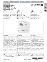
KUVAT
K
uva 1 Kytkentäkaavio
K
uva 2 Anturin vastisarvpt
Kuva 3 Mittakuva
O
J ELECTRONICS A/S
S
tenager 13B · DK-6400 Sønderborg · Denmark
Tel. +45 73 12 13 14 · Fax +45 73 12 13 13
o
[email protected] · www.ojelectronics.com
English
APPLICATION
C
ontrol of electrical heating, floor, ceiling and
r
adiant.
PRODUCT PROGRAMME
ETV with scale range 0/+40°C, 230V AC
ETV-1990 Excl. sensor
E
TV-1991 Incl. floor sensor 3 m
E
TV-1999 Incl. room sensor
ETV with scale range 0/+40°C, 24V AC
ETV-3990 Excl. sensor
E
TV-3991 Incl. floor sensor 3 m
ETV-3999 Incl. room sensor
T
emperature sensors: ETF-.44/99 are suitable.
FUNCTION
T
he temperature is set to the required
t
emperature and the heating output is
energised/de-energised with a difference of only
0
.4°C. LED indication when the relay is
energised.
CE MARKING
OJ Electronics A/S declare under their own
responsibility that this product meets the
requirements of the European Council’s
Directive 89/336 and successive modifications
as to electro-magnetic compatibility and the
Council Directive 73/23 as to electrical
equipment to be applied within certain voltage
ranges.
Standards applied
EN 61000-6-3 , EN 61000-6-2, EN 60 730-1 and
EN 60730-2-9.
The product may only be energised when the
entire installation meets the current directive
requirements.
When the product is installed according to this
instructions guide and the current installation
guidelines, it is covered by factory guarantee.
If the product has been exposed to damage e.g.
in transport, it must be checked and overhauled
by qualified staff before the product is
connected to the power.
TECHNICAL DATA
Supply voltage:
ETV-199x . . .230V AC ±10%, 50-60 Hz
ETV-399x . . . .24V AC ±10%, 50-60 Hz
Max. fuse . . . . . . . . . . . . . . . . . . . . . . . . . . .16A
Output relay . . . . . . . .S.P.S.T. 16A, max. 3.6 kW
On/Off difference . . . . . . . . . . . . . . . . . . . .0.4°C
Operation temperature . . . . . . . . . . . . .0/+50°C
Temperature setback . . . . . . . . . . . . . . . . . .5°C
Power consumption . . . . . . . . . . . . . . . . . . .3 VA
Weight . . . . . . . . . . . . . . . . . . . . . . . . . . . .90 g
Dimensions (HxWxD) . . . . . . . . . .86x36x58 mm
Housing . . . . . . . . . . . . . . . . . . . . . . . . . . .IP 20
Temperature sensor . . . . . . . . . .NTC-thermistor
CLASSIFICATION
The product is a Class II product (reinforced
insulation) and the product must be connected
to the following conductors:
1) Phase (F/L1)
2
) Neutral (N/L2)
SETBACK TEMPERATURE
T
he setback temperature is activated via 230V
(
ETV-199x) or 24V (ETV-399x) voltage signal
f
rom remote contact timer to terminal 3.
Setback temperature is fixed 5°C.
T
EMPERATURE SETTING
ETV has a scale range of 0/+40°C. Red LED
indication when heat is on. The thermostat is
s
et on max. temperature, until the required room
t
emperature has been reached. Then the
thermostat is turned down until the LED turns
o
ff. After 1-2 days a fine adjustment may be
r
equired.
INSTALLATION
E
TV is mounted on a DIN-rail, cover box for wall
m
ounting is obtainable as extra equipment.
Connection according to figure 1.
F
loor sensor: Is mounted in standard conduit
e
mbedded into the floor, and positioned
between the heating cables - and preferably as
close to the floor surface as possible. If
r
equired, the sensor cable can be extended up
t
o 100 m with standard installation cable.
R
oom sensor: The sensor is positioned on the
w
all in such a way that there is free air
circulation above it. Furthermore it should be
placed in such a way that its position is not
i
nfluenced by any form of heating outlet (e.g.
t
he sun) draughts from doors or windows or by
the outside temperature (outside wall).
Sensor cable: The sensor cable must not run in
trunking or in bundles together with other
circuits. The sensor cable should not be laid
parallel to cables which may induce
signals/noise to the sensor signal and thus
disturb the functioning of the thermostat.
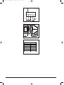
FIGURES
Fig. 1 Connection
Fig. 2 Dimensions
Fig. 3 Sensor table
OJ ELECTRONICS A/S
Stenager 13B · DK-6400 Sønderborg · Denmark
Tel. +45 73 12 13 14 · Fax +45 73 12 13 13
[email protected] · www.ojelectronics.com
Deutsch
ANWENDUNG
Regelung von elektrischen Heizelementen in
Boden und Deckenheizungen, sowie für
Heizkörper.
PRODUKTPROGRAMM
ETV mit Skalenbereich 0/+40°C, 230V AC
ETV-1990 Ausschl. Fühler
ETV-1991 Einschl. Bodenfühler 3 m
ETV-1999 Einschl. Raumfühler
ETV mit Skalenbereich 0/+40°C, 24V AC
ETV-3990 Ausschl. Fühler
ETV-3991 Einschl. Bodenfühler 3 m
ETV-3999 Einschl. Raumfühler
Temperaturfühler: ETF-.44/99 können eingesetzt
werden.
FUNKTION
Der Thermostat wird auf die gewünschte
Temperatur eingestellt und die Heizleistung wird
mit einer Differenz von nur 0,4°C ein- /
ausgeschaltet. Eine Leuchtdiode leuchtet auf,
wenn das Relais aktiviert ist.
CE PRÜFZEICHEN
O
J Electronics A/S erklärt in eigener
V
erantwortung, dass dieses Produkt der
Direktive des Europäischen Rats 89/336 und
d
en nachfolgenden Änderungen betreffs
e
lektromagnetischer Kompatibilität sowie auch
d
er Direktive des Rats 73/23 betreffs
Elektroausrüstung zur Anwendung innerhalb
g
ewissen Spannungsgrenzen entspricht.
Berücksichtigte Standards
EN 61000-6-3 , EN 61000-6-2, EN 60 730-1
u
nd EN 60730-2-9.
Das Produkt darf erst in Betrieb genommen
w
erden, nachdem sichergestellt ist, dass die
G
esamtinstallation die geltenden Forderungen
d
er Direktive erfüllt.
N
achdem das Produkt nach den Anweisungen
d
ieser Bedienungsanleitung und den
Installationsvorschriften montiert ist, ist es von
der Werkgarantie umfasst.
I
st das Produkt z.B. im Transport beschädigt
worden, ist es vom qualifizierten Personal zu
besichtigen und zu prüfen, bevor das Produkt
a
ns Netz angeschlossen wird.
TECHNISCHE DATEN
B
etriebsspannung:
E
TV-199x . . .230V AC ±10%, 50-60 Hz
ETV-399x . . . .24V AC ±10%, 50-60 Hz
Max. Sicherung . . . . . . . . . . . . . . . . . . . . . .16A
A
usgangsrelais Schliessrelais 16A, max. 3,6 kW
H
ysteresis . . . . . . . . . . . . . . . . . . . . . . . . .0,4°C
Betriebstemperatur . . . . . . . . . . . . . . . .0/+50°C
T
emperaturabsenkung . . . . . . . . . . . . . . . . .5°C
Leistungsaufnahme . . . . . . . . . . . . . . . . . . .3 VA
Gewicht . . . . . . . . . . . . . . . . . . . . . . . . . . . .90 g
Abmessungen (HxBxT) . . . . . . . .86x36x58 mm
Gehäuseschutzart . . . . . . . . . . . . . . . . . . . .IP 20
Temperaturfühler . . . . . . . . . . . .NTC-Thermistor
KLASSIFIKATION
Das Produkt ist ein Klasse II Gerät (verstärkte
Isolation) und das Produkt ist an die folgenden
Leiter anzuschliessen:
1) Phase (F/L1)
2) Nulleiter (N/L 2)
TEMPERATURABSENKUNG
Die Temperaturabsenkung wird durch ein 230V
(ETV-199x) oder 24V (ETC-399x)
Spannungssignal von einer externen Kontaktuhr
an Klemme 3 aktiviert. Die Temperatur -
absenkung ist fest 5°C.
TEMPERATUREINSTELLUNG
ETV hat einen Skalenbereich von 0/+40°C. Als
Hilfe bei der Einstellung ist der Thermostat mit
einer Leuchtdiode versehen, die rot aufleuchtet,
sobald die Heizung eingeschaltet ist. Den
Thermostat auf max. Temperatur einstellen, bis
die gewünschte Raumtemperatur erreicht ist.
Dann den Thermostat herunterdrehen, bis die
Leuchtdiode erlischt. Nach 1-2 Tagen kann eine
Feinjustierung notwendig sein.
MONTAGE
Der ETV ist für DIN-Schienen Montage.
Abdeckgehäuse für Wandmontage ist als
Sonderzubehör erhältlich.
Anschluss laut Abb. 1.
Bodenfühler: Wird in ein gewöhnliches
Installationsrohr eingezogen, welches zwischen
den Heizkabeln und so nahe wie möglich an der
Bodenoberfläche in die Bodenkonstruktion
eingelegt wird. Falls notwendig kann das
Fühlerkabel mit einem handelsüblichen
Installationskabel bis auf 100 m verlängert
werden.
3
© 2011 OJ Electronics A/S© 2011 OJ Electronics A/S
57912A-05-11.qxd:57912 25/05/11 9:24 Side 3
Seite laden ...
Seite laden ...
Seite laden ...
Seite laden ...
Seite laden ...
-
 1
1
-
 2
2
-
 3
3
-
 4
4
-
 5
5
-
 6
6
-
 7
7
-
 8
8


in anderen Sprachen
- English: OJ Electronics ETV Operating instructions
- français: OJ Electronics ETV Mode d'emploi
- dansk: OJ Electronics ETV Betjeningsvejledning
- polski: OJ Electronics ETV Instrukcja obsługi
- svenska: OJ Electronics ETV Bruksanvisningar
- suomi: OJ Electronics ETV Käyttö ohjeet
Verwandte Papiere
-
OJ Electronics OCC3 Benutzerhandbuch
-
-
-
 OJ OCD2 Bedienungsanleitung
-
-
-
OJ Electronics OCC4 Bedienungsanleitung
-
-
-
OJ Electronics OCD5 Bedienungsanleitung

Sonstige Unterlagen
-
 De Dietrich DIEMATIC Bedienungsanleitung
-
APRILIA ETV MILLE CAPONORD Bedienungsanleitung
-
AEG 400541 Datenblatt
-
ASCOM Eurit 4000 Benutzerhandbuch
-
SwissVoice Eurit 266 Benutzerhandbuch
-
SwissVoice Eurit 535 565 Benutzerhandbuch
-
AEG Electrolux VL 5530 S Bedienungsanleitung
-
STIEBEL ELTRON RTU-TC Instructions Manual
-
-
Tyco T2DuoTemp Benutzerhandbuch
