SICK CM18 DC/CM30 DC/CQ35 DC/CM30 AC/CM18 PTFE Bedienungsanleitung
- Typ
- Bedienungsanleitung

BZ int48
Please find detailed addresses and further locations in all major industrial
nations at www.sick.com
Australia
Phone +61 (3) 9457 0600
Austria
Phone +43 (0) 2236 62288-0
Belgium/Luxembourg
Phone +32 (0) 2 466 55 66
Brazil
Phone +55 11 3215-4900
Canada
Phone +1 905.771.1444
Czech Republic
Phone +420 2 57 91 18 50
Chile
Phone +56 (2) 2274 7430
China
Phone +86 20 2882 3600
Denmark
Phone +45 45 82 64 00
Finland
Phone +358-9-25 15 800
France
Phone +33 1 64 62 35 00
Germany
Phone +49 (0) 2 11 53 01
Hong Kong
Phone +852 2153 6300
Hungary
Phone +36 1 371 2680
India
Phone +91-22-6119 8900
Israel
Phone +972-4-6881000
Italy
Phone +39 02 27 43 41
Japan
Phone +81 3 5309 2112
Malaysia
Phone +603-8080 7425
Mexico
Phone +52 (472) 748 9451
Netherlands
Phone +31 (0) 30 229 25 44
New Zealand
Phone +64 9 415 0459
Norway
Phone +47 67 81 50 00
Poland
Phone +48 22 539 41 00
Romania
Phone +40 356-17 11 20
Russia
Phone +7 495 283 09 90
Singapore
Phone +65 6744 3732
Slovakia
Phone +421 482 901 201
Slovenia
Phone +386 591 78849
South Africa
Phone +27 (0)11 472 3733
South Korea
Phone +82 2 786 6321
Spain
Phone +34 93 480 31 00
Sweden
Phone +46 10 110 10 00
Switzerland
Phone +41 41 619 29 39
Taiwan
Phone +886-2-2375-6288
Thailand
Phone +66 2 645 0009
Turkey
Phone +90 (216) 528 50 00
United Arab Emirates
Phone +971 (0) 4 88 65 878
United Kingdom
Phone +44 (0)17278 31121
USA
Phone +1 800.325.7425
Vietnam
Phone +65 6744 3732
CM18DC/CM30DC/
CQ35DC/CM30AC/
CM18PTFE
---------------------------------------------------------------------------------------------------------------------------------------------------------------------------------------------------------------------------------------------------
SICK AG, Erwin-Sick-Strasse 1, D-79183 Waldkirch
A
-------------------------------------------------------------------------------- 8008989.10R9 0119 COMAT ------------------------------------------------------------------------------
ENGLISH
Capacitive Proximity Sensor
Operating Instructions
Safety Specifications
• Read the operating instructions before starting operation.
•
Connection, assembly, and settings only by competent techni-
cians.
• Protect the device against moisture and soiling when operating.
•
2006/42/EG
NO
SAFETY
No safety component in accordance with EU machine
guidelines.
• Fuse protection of cable for CM30AC required.
Proper Use
The proximity sensor is a capacitive sensor and is used for contactless
detecting of objects, animals and persons.
Starting Operation
A capacitive proximity sensor detects metallic and non-metallic
objects. The given switching distance for capacitive proximity
sensors is based on standardized measurement plate made of
steel (ST37). Use the appropriate correction factor if other objects
are used.
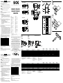
!
Mount the proximity sensor on a suitable bracket (e.g., SICK
mounting bracket). Supply operational voltage (see nameplate).
With following connectors only:
Connect and secure cable receptacle tension-free.
Only for versions with connecting cable:
The following apply for connection in B: bn = brown, bu = blue,
bk = black, wh = white.
Connect cables.
"
Pay attention to application conditions such as switching distance
and mutual interference.
§
Setting the switching threshold:
Set potentiometer to max. (default setting). Position object. Align
sensor to object. The LED signal strength indicator must light. If it
does not light, check the distance between sensor and object (sn).
Remove object. The LED signal strength indicator must switch o.
If it does not switch o, reduce the sensitivity on the potentiometer
until the LED signal strength indicator switches o. Reposition the
object, the LED signal strength indicator must light. Remove the
object; the LED signal strength indicator must switch o. If it does
not switch o, reduce the sensitivity further on the potentiometer
until the LED signal strength indicator switches o. Remove the
object.
In EMC critical applications, conducted interference levels may lie
in the frequency range of the oscillator. This can cause changes to
the output signal. The oscillator frequencies for each of the product
families may be taken from the following listing:
CM18-08… 0.56 MHz … 1.35 MHz
CM18-12… 0.62 MHz … 1.30 MHz
CM30-16BPP… 0.60 MHz … 1.10 MHz
CM30-16BNP… 0.55 MHz … 1.70 MHz
CM30-16BAP… 0.48 MHz … 0.90 MHz
CM30-25NPP… 0.52 MHz … 1.90 MHz
CM30-25NNP… 0.54 MHz … 1.90 MHz
CM30-25NAP… 0.49 MHz … 1.85 MHz
CQ35-25NPP… 0.65 MHz … 1.75 MHz
CQ35-25NNP… 0.70 MHz … 1.80 MHz
In order to minimize conducted fault susceptibility from electromag-
netic radiation, it is recommended to ground the target (the item to be
detected) and/or to lter the wiring.
Maintenance
SICK sensors do not require any maintenance. We recommend that you
clean the external lens surfaces and check the screw connections and
plug-in connections at regular intervals.
DEUTSCH
Kapazitiver Näherungssensor
Betriebsanleitung
Sicherheitshinweise
• Vor der Inbetriebnahme die Betriebsanleitung lesen.
•
Anschluss, Montage und Einstellung nur durch Fachpersonal.
• Gerät bei Inbetriebnahme vor Feuchte und Verunreinigung
schützen.
•
2006/42/EG
NO
SAFETY
Kein Sicherheitsbauteil gemäß EU-Maschinenrichtlinie.
• Leitungsabsicherung für CM30AC erforderlich.
Bestimmungsgemäße Verwendung
Der Näherungssensor ist ein kapazitiver Sensor und wird zum berüh-
rungslosen Erfassen von Sachen, Tieren und Personen eingesetzt.
Inbetriebnahme
Ein kapazitiver Näherungssensor erfasst metallische und nicht-
metallische Objekte. Der angegebene Schaltabstand für kapaziti-
ve Näherungssensoren bezieht sich auf eine genormte Messplatte
aus Stahl (ST37). Bei der Verwendung anderer Objekte ist der
jeweilige Korrekturfaktor zu berücksichtigen.
!
Näherungssensor an geeignete Halter montieren (z. B. SICK-
Haltewinkel). Näherungssensor an Betriebsspannung legen
(s. Typenaufdruck).
Nur bei den Steckerversionen:
Leitungsdose spannungsfrei aufstecken und festschrauben.
Nur bei den Versionen mit Anschlussleitung:
Für Anschluss in B gilt: bn = braun, bu = blau, bk = schwarz,
wh = weiß.
Leitungen anschließen.
"
Einsatzbedingungen wie Schaltabstand und gegenseitige Beein-
ussung beachten.
§
Einstellung Schaltschwelle:
Potentiometer auf Max. stellen (werkseitige Voreinstellung).
Objekt positionieren. Sensor auf Objekt ausrichten. Empfangsan-
zeige muss leuchten. Leuchtet sie nicht, Abstand Sensor – Objekt
(sn) überprüfen. Objekt entfernen, Empfangsanzeige muss
erlöschen. Erlischt sie nicht, Empndlichkeit am Potentiometer re-
duzieren, bis Empfangsanzeige erlischt. Objekt neu positionieren,
Empfangsanzeige muss leuchten. Objekt entfernen, Empfangs-
anzeige muss erlöschen, erlischt sie nicht, Empndlichkeit am
Potentiometer weiter reduzieren, bis Empfangsanzeige erlischt.
Objekt entfernen.
In EMV-kritischen Applikationen können leitungsgeführte Störgrößen
im Frequenzbereich des Oszillators liegen. Dies kann zu Veränderungen
des Ausgangssignals führen. Die Oszillatorfrequenzen der jeweiligen
Produktfamilien können Sie der nachfolgenden Auistung entnehmen:
CM18-08… 0,56 MHz … 1,35 MHz
CM18-12… 0,62 MHz … 1,30 MHz
CM30-16BPP… 0,60 MHz … 1,10 MHz
CM30-16BNP… 0,55 MHz … 1,70 MHz
CM30-16BAP… 0,48 MHz … 0,90 MHz
CM30-25NPP… 0,52 MHz … 1,90 MHz
CM30-25NNP… 0,54 MHz … 1,90 MHz
CM30-25NAP… 0,49 MHz … 1,85 MHz
CQ35-25NPP… 0,65 MHz … 1,75 MHz
CQ35-25NNP… 0,70 MHz … 1,80 MHz
Um die leitungsgeführte Störanfälligkeit gegenüber elektromag-
netischer Strahlung zu minimieren, empehlt es sich das Target
(zu detektierendes Objekt) zu erden und/oder eine Belterung der
Zuleitung durchzuführen.
Wartung
SICK-Sensoren sind wartungsfrei. Wir empfehlen, in regelmäßigen
Abständen
– die Grenzächen zu reinigen,
– Verschraubungen und Steckverbindungen zu überprüfen.
More representatives and agencies at www.sick.com ∙ Subject to change
without notice ∙ The specied product features and technical data do not
represent any guarantee.
Weitere Niederlassungen nden Sie unter www.sick.com ∙ Irrtümer
und Änderungen vorbehalten ∙ Angegebene Produkteigenschaften und
technische Daten stellen keine Garantieerklärung dar.
Plus de représentations et d’agences à l’adresse www.sick.com ∙ Sujet à
modication sans préavis ∙ Les caractéristiques de produit et techniques
indiquées ne constituent pas de déclaration de garantie.
Para mais representantes e agências, consulte www.sick.com ∙ Alterações
poderão ser feitas sem prévio aviso ∙ As características do produto e os
dados técnicos apresentados não constituem declaração de garantia.
Altri rappresentanti ed agenzie si trovano su www.sick.com ∙ Contenuti
soggetti a modiche senza preavviso ∙ Le caratteristiche del prodotto e i dati
tecnici non rappresentano una dichiarazione di garanzia.
Más representantes y agencias en www.sick.com ∙ Sujeto a cambio sin
previo aviso ∙ Las características y los datos técnicos especicados no
constituyen ninguna declaración de garantía.
欲了解更多代表机构和代理商信息,请登录 www.sick.com ∙
如有更改, 不另行通知 ∙ 对所给出的产品特性和技术参数
的正确性不予保证。
その他の営業所はwww.sick.com よりご覧ください ・ 予告なしに変更され
ることがあります ・ 記載されている製品機能および技術データは保証を明
示するものではありません。
!
B
"
§
CQ35DCCM18DC/CM18PTFE
CM30DC/CM30AC
CM18-08B
CM30-16B
CM30AC
CM18PTFE
CM18-12N
CM30-25N
CQ35-25N
CM30AC
CM 30 AC
CM 30 AC
CM 18 PTFE
CM18DC
CM30DC
CQ35DC
CM18PTFE
CM18DC
CM30DC
CQ35DC
CM18PTFE
20 - 250 V AC
10 - 500 mA
EC30
NC
NO
CM30AC (SCR, NO or/oder NC)
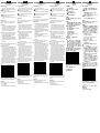
CM18PTFE CM18DC CM30DC CQ35DC CM30AC
Supply voltage V
S
1)
Versorgungsspannung U
V
1)
Tension d’alimentation U
V
1)
Tensão de força U
V
1)
10 ... 36 V DC 10 ... 36 V DC 10 ... 36 V DC 10 ... 36 V DC 20 ... 250 V AC
Output current I
max
Ausgangsstrom I
max
Courant de sortie I
maxi
Corrente de saída I
máx
200 mA 200 mA 200 mA 200 mA 500 mA
Signal sequence Schaltfrequenz Fréquence Sequência mín. de sinais 30/s 30/s 50/s 50/s 10/s
Standby delay Bereitschaftsverzögerung Temporisation à la disponibilité Retardo do estado de protidão ≤ 100 ms ≤ 100 ms ≤ 100 ms ≤ 100 ms ≤ 100 ms
Enclosure rating Schutzart Type de protection Tipo de proteção IP 67 IP 67 IP 67 IP 67 IP 67
Circuit protection
2)
Schutzschaltungen
2)
Circuits de protection
2)
Circuitos protetores
2)
A, B, D A, B, D A, B, D A, B, D A, B, C
Protection class Schutzklasse Classe de protection Classe de proteção
Ambient operating temperature Betriebsumgebungstemperatur Température ambiante Temperatura ambiente de operação –25 ... +60 °C –25 ... +80 °C –25 ... +80 °C –25 ... +75 °C –25 ... +80 °C
Ambient storage temperature Lagertemperatur Température ambiante stockage Temperatura ambiente depósito –25 ... +60 °C –40 ... +85 °C –40 ... +85 °C –40 ... +85 °C –40 ... +85 °C
1)
Limits
Residual ripple max. 5 V
PP
2)
A = V
S
connections reverse polarity protected
B = inputs/outputs reverse polarity protected
C = interference pulse suppression
D = outputs protected against excess current
and short circuits
1)
Grenzwerte
Restwelligkeit max. 5 V
SS
2)
A = U
V
-Anschlüsse verpolsicher
B = Ein-/Ausgänge verpolsicher
C = Störimpulsunterdrückung
D = Ausgänge überstrom- und kurzschlussfest
1)
Valeurs limites
Ondulation résiduelle maxi 5 V
SS
2)
A = Raccordements U
V
protégés contre les
inversions de polarité
B = Entrées/Sorties protégées contre les
inversions de polarité
C = Suppression des impulsions parasites
D = Sorties protégées contre les surcharges et
les courts-circuits
1)
Valores limite
Ondulação residual máx. 5 V
SS
2)
A = Conexões U
V
protegidas contra inversão de
polos
B = Entradas/saídas protegidas contra inversão
de polos
C = Supressão de impulsos parasitas
D = Saídas protegidas contra sobrecarga e
curto circuito
CM18PTFE CM18DC CM30DC CQ35DC CM30AC
Tensione di alimentazione U
V
1)
Tensión de alimentación U
V
1)
电源电压 U
V
1)
供給電圧 U
V
1)
10 ... 36 V DC 10 ... 36 V DC 10 ... 36 V DC 10 ... 36 V DC 20 ... 250 V AC
Corrente di uscita max. I
max
Corriente de salida I
max.
.
输出电流
I
max
最大出力電流 I
max
200 mA 200 mA 200 mA 200 mA 500 mA
Sequenza signali Secuencia de señales
信号流 スイッチング周波数
30/s 30/s 50/s 50/s 10/s
Ritardo di disponibilità Retardo de disponibilidad
延缓准备 スタンバイ遅延
≤ 100 ms ≤ 100 ms ≤ 100 ms ≤ 100 ms ≤ 100 ms
Tipo di protenzione Tipo de protección
保护种类 保護等級
IP 67 IP 67 IP 67 IP 67 IP 67
Commutazioni di protezione
2)
Circuitos de protección
2)
保护电路
2)
保護回路
2)
A, B, D A, B, D A, B, D A, B, D A, B, C
Classe di protezione Protección clase
保护级别 保護クラス
Temperatura ambiente circostante Temperatura ambiente de servicio
工作环境-温度 動作周囲温度
–25 ... +60 °C –25 … +80 °C –25 … +80 °C –25 … +75 °C –25 ... +80 °C
Temperatura ambiente magazzino Temperatura ambiente almacén
工作室温 保管温度
–25 ... +60 °C –40 ... +85 °C –40 ... +85 °C –40 ... +85 °C –40 ... +85 °C
1)
Valori limite
ondulatione residua max. 5 V
SS
2)
A = U
V
-collegamenti con protez. contro
inversione di poli
B = entrate/uscite con protezione contro
invesione di poli
C = soppressione impulsi di disturbo
D = uscite a prova di sovraccorrente e corto
circuito
1)
Valores límite
ondulación residual max. 5 V
SS
2)
A = Conexiones U
V
a prueba de inversión de
polaridad
B = Entradas/salidad a prueba de inversión de
polaridad
C = Represión de impulso de interferencia
D = Salidas de corriente de sobreintensidad y
resistentes al cortocircuito
1)
极限值剩余波纹度 max. 5 V
SS
2)
A = U
V
- 接头防反接
B = 输入/输出防反接
C = 消除干扰脉冲
D = 输出端抗过流-及短路.
1)
限界値
最大残留リップル電圧 5Vp-p
2)
A = U
V
コネクタ 逆接保護
B = 入力および出力の逆接保護
C = 干渉パルス抑制
D = 出力の過電流保護および短絡保護
F <0,5A EC60127-2 sheet 1
0,34 mm
2
/ AW
G 22
0,34 mm
2
/ AW
G 22
Seite wird geladen ...
-
 1
1
-
 2
2


SICK CM18 DC/CM30 DC/CQ35 DC/CM30 AC/CM18 PTFE Bedienungsanleitung
- Typ
- Bedienungsanleitung
in anderen Sprachen
- English: SICK CM18 DC/CM30 DC/CQ35 DC/CM30 AC/CM18 PTFE Operating instructions
- français: SICK CM18 DC/CM30 DC/CQ35 DC/CM30 AC/CM18 PTFE Mode d'emploi
- español: SICK CM18 DC/CM30 DC/CQ35 DC/CM30 AC/CM18 PTFE Instrucciones de operación
- italiano: SICK CM18 DC/CM30 DC/CQ35 DC/CM30 AC/CM18 PTFE Istruzioni per l'uso
- português: SICK CM18 DC/CM30 DC/CQ35 DC/CM30 AC/CM18 PTFE Instruções de operação
- 日本語: SICK CM18 DC/CM30 DC/CQ35 DC/CM30 AC/CM18 PTFE 取扱説明書
Verwandte Artikel
-
SICK CM18 / CM30 Basic Bedienungsanleitung
-
-
-
-
-
-
-