SICK CM18DC/CM30DC Operating Instruction Bedienungsanleitung
- Typ
- Bedienungsanleitung

BZ int44
Please find detailed addresses and additional representatives and agencies in
all major industrial nations at www.sick.com
Australia
Phone +61 3 9457 0600
Austria
Phone +43 (0)22 36 62 28 8-0
Belgium/Luxembourg
Phone +32 (0)2 466 55 66
Brazil
Phone +55 11 3215-4900
Canada
Phone +1 905 771 14 44
Czech Republic
Phone +420 2 57 91 18 50
Chile
Phone +56 2 2274 7430
China
Phone +86 4000 121 000
+852-2153 6300
Denmark
Phone +45 45 82 64 00
Finland
Phone +358-9-2515 800
France
Phone +33 1 64 62 35 00
Germany
Phone +49 211 5301-301
Great Britain
Phone +44 (0)1727 831121
Hong Kong
Phone +852 2153 6300
Hungary
Phone +36 1 371 2680
India
Phone +91–22–4033 8333
Israel
Phone +972-4-6881000
Italy
Phone +39 02 27 43 41
Japan
Phone +81 (0)3 5309 2112
Malaysia
Phone +603 808070425
Netherlands
Phone +31 (0)30 229 25 44
New Zealand
Phone +64 9 415 0459
Norway
Phone +47 67 81 50 00
Poland
Phone +48 22 837 40 50
Romania
Phone +40 356 171 120
Russia
Phone +7-495-775-05-30
Singapore
Phone +65 6744 3732
Slovakia
Phone +421 482 901201
Slovenia
Phone +386 (0)1-47 69 990
South Africa
Phone +27 11 472 3733
South Korea
Phone +82 2 786 6321
Spain
Phone +34 93 480 31 00
Sweden
Phone +46 10 110 10 00
Switzerland
Phone +41 41 619 29 39
Taiwan
Phone +886 2 2375-6288
Thailand
Phone +66 2645 0009
Turkey
Phone +90 (216) 528 50 00
United Arab Emirates
Phone +971 (0) 4 88 65 878
USA/México
Phone +1(952) 941-6780
Vietnam
Phone +84 8 62920204
CM18DC/CM30DC
---------------------------------------------------------------------------------------------------------------------------------------------------------------------------------------------------------------------------------------------------
SICK AG, Erwin-Sick-Strasse 1, D-79183 Waldkirch
A
----------------------------------------------------------------------------------------- 8018777 1115 COMAT ---------------------------------------------------------------------------------------
ENGLISH
Capacitive proximity sensor
Operating instructions
Safety notes
• Read the operating instructions before commissioning.
• Connection, mounting, and programming may only be performed
by trained specialists.
• When commissioning, protect the device from moisture and
contamination.
• Not a safety component in accordance with the EU Machinery
Directive.
Correct use
Capacitive proximity sensors are suitable for detecting solid and liquid
materials. This includes all metals and non-metallic substances.
Commissioning
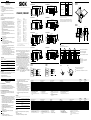
A capacitive proximity sensor can detect metallic and non-
metallic objects / media. The sensing range given for capacitive
proximity sensors relates to a measuring plate of standardized
steel (ST37). The required correction factor must be considered
when using dierent objects.
Mount the proximity sensor on an appropriate bracket (such as a
SICK mounting adapter). Apply the proximity sensor to operating
voltage.
For the connector versions only:
Insert the female cable connector with the power o and fasten
in place.
For the connecting cable versions only:
For connection in B, the following applies: bn = brown, bu = blue,
bk = black, wh = white.
Connect the cables.
1 Pay attention to application conditions such as switching distance
and mutual interference.
2 Conguration:
Conguring to the object /media:
1.) Position the object /media in front of the sensor.
2.) Turn the potentiometer clockwise until the yellow and green
LEDs light up without ashing.
3.) You have successfully congured the constantly ON state.
Background subtraction
(“Background” here covers any and all ambient conditions which
are not directly related to the object /media)
1.) Place the sensor in the application location. The area in front
of the sensor must be clear of objects /media.
2.) Turn the potentiometer clockwise until the yellow LED lights
up, then turn it counterclockwise until the yellow LED goes out
and the green LED lights up without ashing.
3.) You have successfully congured the constantly OFF state.
LED indication
Green LED Yellow LED
ON
OFF
The power is on and the sensor is in a stable
OFF state.
OFF
OFF
The output is OFF, and the target is not
detected.
OFF ON
The output ON, and the target is detected.
ON ON
The output is ON and the sensor is in a stable
ON state.
Maintenance
SICK sensors do not require maintenance. We do, however, recommend
that the following activities are undertaken regularly:
– Cleaning the external surfaces.
– Checking screw connections and plug connectors.
DEUTSCH
Kapazitiver Näherungssensor
Betriebsanleitung
Sicherheitshinweise
• Vor der Inbetriebnahme die Betriebsanleitung lesen.
• Anschluss, Montage und Einstellung nur durch Fachpersonal.
• Gerät bei Inbetriebnahme vor Feuchte und Verunreinigung schützen.
• Kein Sicherheitsbauteil gemäß EU-Maschinenrichtlinie.
Bestimmungsgemäße Verwendung
Kapazitive Näherungssensoren eignen sich zum Erfassen von Ma-
terialien in fester und üssiger Form. Dazu gehören alle Metalle und
nicht-metallische Stoe.
Inbetriebnahme
Ein kapazitiver Näherungssensor erfasst metallische und nichtme-
tallische Objekte / Medien. Der angegebene Schaltabstand (S
n
)
für kapazitive Näherungssensoren bezieht sich auf eine genormte
Messplatte aus Stahl (ST37). Bei der Verwendung anderer Objekte
ist der jeweilige Korrekturfaktor zu berücksichtigen.
Näherungssensor an geeignete Halter montieren (z. B. SICK
Haltewinkel). Näherungssensor an Betriebsspannung legen.
Nur bei den Steckerversionen:
Leitungsdose spannungsfrei aufstecken und festschrauben.
Nur bei den Versionen mit Anschlussleitung:
Für Anschluss in B gilt: bn = braun, bu = blau, bk = schwarz,
wh = weiß.
Leitungen anschließen.
1 Einsatzbedingungen wie Schaltabstand und gegenseitige
Beeinussung beachten.
2 Einstellung:
Einstellung auf das Objekt / Medium:
1.) Platzieren Sie das Objekt / Medium vor dem Sensor.
2.) Drehen Sie das Potentiometer im Uhrzeigersinn, bis die gelbe
und die grüne LED dauerhaft leuchten.
3.) Sie haben die Einstellung für den stabilen EIN-Zustand
erreicht.
Eliminierung des Hintergrunds:
(Als Hintergrund sind alle Umgebungsbedingungen zu betrachten,
die nicht das direkte Objekt / Medium darstellen)
1.) Platzieren Sie den Sensor an der Anwendungsposition. Es darf
sich kein Objekt / Medium vor dem Sensor benden.
2.) Drehen Sie das Potentiometer im Uhrzeigersinn, bis die gelbe
LED aueuchtet und dann entgegen dem Uhrzeigersinn, bis
die gelbe LED erlischt und die grüne LED dauerhaft leuchtet.
3.) Sie haben die Einstellung für den stabilen AUS-Zustand
erreicht.
LED Anzeige
Grüne LED Gelbe LED
AN AUS
Die Stromversorgung ist hergestellt und der Sen-
sor befindet sich in einem stabilen AUS-Zustand.
AUS
AUS
Der Ausgang ist deaktiviert (AUS) und es wird kein
Ziel erkannt.
AUS AN
Der Ausgang ist aktiviert (EIN) und das Ziel wird
erkannt.
AN AN
Der Ausgang ist aktiviert (EIN) und der Sensor
befindet sich in einem stabilen EIN-Zustand.
Wartung
SICK-Sensoren sind wartungsfrei. Wir empfehlen, in regelmäßigen
Abständen
– die Grenzächen zu reinigen,
– Verschraubungen und Steckverbindungen zu überprüfen.
More representatives and agencies at www.sick.com ∙ Subject to change
without notice ∙ The specied product features and technical data do not
represent any guarantee.
Weitere Niederlassungen nden Sie unter www.sick.com ∙ Irrtümer
und Änderungen vorbehalten ∙ Angegebene Produkteigenschaften und
technische Daten stellen keine Garantieerklärung dar.
Plus de représentations et d’agences à l’adresse www.sick.com ∙ Sujet à
modication sans préavis ∙ Les caractéristiques de produit et techniques
indiquées ne constituent pas de déclaration de garantie.
Para mais representantes e agências, consulte www.sick.com ∙ Alterações
poderão ser feitas sem prévio aviso ∙ As características do produto e os
dados técnicos apresentados não constituem declaração de garantia.
Altri rappresentanti ed agenzie si trovano su www.sick.com ∙ Contenuti
soggetti a modiche senza preavviso ∙ Le caratteristiche del prodotto e i dati
tecnici non rappresentano una dichiarazione di garanzia.
Más representantes y agencias en www.sick.com ∙ Sujeto a cambio sin
previo aviso ∙ Las características y los datos técnicos especicados no
constituyen ninguna declaración de garantía.
欲了解更多代表机构和代理商信息,请登录 www.sick.com ∙
如有更改, 不另行通知 ∙ 对所给出的产品特性和技术参数
的正确性不予保证。
その他の営業所はwww.sick.com よりご覧ください ・ 予告なしに変更され
ることがあります ・ 記載されている製品機能および技術データは保証を明
示するものではありません。
B
1
2
≥ 2d d
d
≥ 3 S
n
≥ 3 S
n
d
≥ 2 S
n
d
d
d
d
CM18-08B
CM30-16B
CM18
CM30
CM18-12N
CM30-25N
CM 18-08B
-12N
CM 30-16B
-25N
8
12
16
25
max. S
[mm]
n
CM18DC
CM30DC
CM18DC
CM30DC
PNP
bn
bk
wh
bu
1
4
2
3
DC
NPN
bn
bk
wh
bu
1
4
2
3
DC
CM18DC CM30DC
Supply voltage V
S
1)
Versorgungsspannung U
V
1)
Tension d’alimentation U
V
1)
Tensão de força U
V
1)
10 ... 36 V DC 10 ... 36 V DC
Output current I
max
Ausgangsstrom I
max
Courant de sortie I
max
Corrente de saída I
max
200 mA 200 mA
Signal sequence Schaltfrequenz Fréquence Sequência mín. de sinais 50 Hz 50 Hz
Standby delay Bereitschaftsverzögerung Temporisation à la disponibilité Retardo do estado de protidão ≤ 100 ms ≤ 100 ms
Enclosure rating Schutzart Type de protection Tipo de proteção IP 68, IP 69K IP 68, IP 69K
Circuit protection
2)
Schutzschaltungen
2)
Circuits de protection
2)
Circuitos protetores
2)
A, B, D A, B, D
Tightening torque Anzugsdrehmoment Couple de serrage Torque de aperto <= 2.6 Nm <= 7.5 Nm
Ambient operating temperature Betriebsumgebungstemperatur Température ambiante Temperatura ambiente de operação –30 ° ... +85 °C –30 ° ... +85 °C
Ambient storage temperature Lagertemperatur Température ambiante stockage Temperatura ambiente depósito –40 ... +85 °C –40 ... +85 °C
1)
Limits
Residual ripple max. 5 V
PP
2)
A = V
S
connections reverse polarity protected
B = inputs/outputs reverse polarity protected
C = interference pulse suppression
D = outputs protected against excess current and short
circuits
1)
Grenzwerte
Restwelligkeit max. 5 V
SS
2)
A = U
V
-Anschlüsse verpolsicher
B = Ein-/Ausgänge verpolsicher
C = Störimpulsunterdrückung
D = Ausgänge überstrom- und kurzschlussfest
1)
Valeurs limites
Ondulation résiduelle max. 5 V
CC
2)
A = Raccordements U
V
protégés contre les inversions
de polarité
B = Entrées/Sorties protégées contre les inversions
de polarité
C = Suppression des impulsions parasites
D = Sorties protégées contre les surcharges et les
courts-circuits
1)
Valores limite
Ondulação residual max. 5 V
SS
2)
A = Conexões U
V
protegidas contra inversão de polos
B = Entradas/saídas protegidas contra inversão de polos
C = Supressão de impulsos parasitas
D = Saídas protegidas contra sobrecarga e curto circuito
CM18DC CM30DC
Tensione di alimentazione U
V
1)
Tensión de alimentación U
V
1)
电源电压 U
V
1)
供給電圧 U
V
1)
Напряжение питания U
V
1)
10 ... 36 V DC 10 ... 36 V DC
Corrente di uscita max. I
max
Corriente de salida I
max
输出电流 I
max
最大出力電流 I
max
Выходной ток I
max
200 mA 200 mA
Sequenza signali Secuencia de señales
信号流 スイッチング周波数
Частота переключения 50 Hz 50 Hz
Ritardo di disponibilità Retardo de disponibilidad
延缓准备 スタンバイ遅延
Задержка перед готовностью ≤ 100 ms ≤ 100 ms
Tipo di protenzione Tipo de protección
保护种类 保護等級
Степень защиты IP 68, IP 69K IP 68, IP 69K
Commutazioni di protezione
2)
Circuitos de protección
2)
保护电路
2)
保護回路
2)
Схемы защиты
2)
A, B, D A, B, D
Coppia di serraggio Par de giro
拧紧力矩 締付トルク
Момент затяжки <= 2.6 Nm <= 7.5 Nm
Temperatura ambiente circostante Temperatura ambiente de servicio
工作环境-温度 動作周囲温度
Диапазон рабочих температур –30 ° ... +85 °C –30 ° ... +85 °C
Temperatura ambiente magazzino Temperatura ambiente almacén
工作室温 保管温度
Температура хранения –40 ... +85 °C –40 ... +85 °C
1)
Valori limite
ondulatione residua max. 5 V
SS
2)
A = U
V
-collegamenti con protez. contro inversione di poli
B = entrate/uscite con protezione contro invesione di poli
C = soppressione impulsi di disturbo
D = uscite a prova di sovraccorrente e corto circuito
1)
Valores límite
ondulación residual max. 5 V
SS
2)
A = Conexiones U
V
a prueba de inversión de polaridad
B = Entradas/salidad a prueba de inversión de polaridad
C = Represión de impulso de interferencia
D = Salidas de corriente de sobreintensidad y resistentes al
cortocircuito
1)
极限值剩余波纹度 max. 5 V
SS
2)
A = U
V
- 接头防反接
B = 输入/输出防反接
C = 消除干扰脉冲
D = 输出端抗过流-及短路
1)
限界値
最大残留リップル電圧 5 V
pp
2)
A = U
V
コネクタ 逆接保護
B = 入力および出力の逆接保護
C = 干渉パルス抑制
D = 出力の過電流保護および短絡保護
1)
Предельные значения
остаточной пульсации макс. 5 V
SS
2)
A = разъемы питания с защитой от неправильной
полярности
B = входы/выходы с защитой от неправильной полярности
C = подавление импульсных помех
D = выходы с защитой от перенапряжения и короткого
замыкания
Stable OFF / Stabiler AUS-Zustand
Output OFF / Ausgang AUS
Output ON / Ausgang EIN
Stable ON / Stabiler EIN-Zustand
Ta
rget influence
Einwirkung des Objektes/Mediums
Time / Zeit
Green LED ON / Grüne LED an
Yellow LED ON / Gelbe LED an
Output NO
Output NC
86
(3.39)
70 (2.76)
15
(0.59)
LED
M18 x 1 x 55
LED
M18 x 1 x 55
M12 x 1
85 (3.35)
70 (2.76)
15
(0.59)
86 (3.39)
70 (2.76)
15
(0.59)
LED
M18 x 1 x 47
8 (0.31)
LED
M18 x 1 x 47
M12 x 1
85 (3.35)
70 (2.76)
15
(0.59)
8 (0.31)
LED
81
(3.19)
61 (2.4)
M30 x 1.5 x 59.5
LED
M30 x 1.5 x 59.5
M12 x 1
74 (2.91)
61 (2.4)
81
(3.19)
61 (2.4)
14.5 (0.57)
LED
M30 x 1.5 x 45.5
LED
74 (2.91)
61 (2.4)
14.5 (0.57)
M30 x 1.5 x 45.5
M12 x 1
3 x d
1
3 x d
1
d
1
d
1
≥2 x S
n
CM18-12Nxx-EW1
For flush type sensor flush mounted in conductive material, the usable
sensing range (S
n
) is less than shown in the table above for temperatures
exceeding 0 ... 60 ° C (32 ... 140 °F).
Bündige Sensoren, die bündig in leitfähigen Materialien eingebaut
werden, haben einen etwas geringeren nutzbaren Schaltabstand (S
n
) für
Einsatztemperaturen die außerhalb 0 ... +60 °C (32 ... 140 °F) liegen.
1
Sensitivity ajustment / Empfindlichkeitseinsteller
2
Yellow LED/Output / Gelbe LED/Ausgang
3
Green LED/Stable ON/OFF / Güne LED/Stabiler Ein-/Aus-Zustand
CM18-08Bxx-EC1
CM18-08Bxx-EW1
CM18-12Nxx-EC1
CM30-16Bxx-EW1
CM30-16Bxx-EC1
CM30-25Nxx-EW1
CM30-25Nxx-EC1
Seite wird geladen ...
-
 1
1
-
 2
2


SICK CM18DC/CM30DC Operating Instruction Bedienungsanleitung
- Typ
- Bedienungsanleitung
in anderen Sprachen
- English: SICK CM18DC/CM30DC Operating Instruction Operating instructions
- français: SICK CM18DC/CM30DC Operating Instruction Mode d'emploi
- español: SICK CM18DC/CM30DC Operating Instruction Instrucciones de operación
- italiano: SICK CM18DC/CM30DC Operating Instruction Istruzioni per l'uso
- русский: SICK CM18DC/CM30DC Operating Instruction Инструкция по эксплуатации
- português: SICK CM18DC/CM30DC Operating Instruction Instruções de operação
- 日本語: SICK CM18DC/CM30DC Operating Instruction 取扱説明書
Verwandte Artikel
-
SICK CM18 / CM30 Basic Bedienungsanleitung
-
-
-
-
-
-
-
-
-