SICK Cold-resistent cables no. 2030065/no. 2049613/no. 2031034 for CLV480, CLV/X490 Bar Code Scanner Mounting instructions
- Typ
- Mounting instructions

© SICK AG · Division Auto Ident · Germany · All rights reserved 1 # 28010872/T183/2009-02
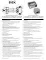
1. Produkteigenschaften
■ Kälteresistente Leitung für einen Barcodescanner CLV480,
CLV490 oder CLX490 mit Heizung zum Anschluss an das
Anschlussmodul CDM490-0001 (IP 65)
■ Temperaturbereich: –35 ... +40 °C
■ Schleppkettentauglich
■ Querschnitt der Versorgungsleitungen: 1,5 mm
2
■ Integrierter Parameterspeicher in Steckerhaube
■ Signale des Barcodescanners geschirmt auf D-Sub-Stecker/-
Buchse, Versorgungsleitung geschirmt auf offenes Ende
■ Schutzart IP 65
■ Länge: 3 m (Nr. 2030065), 5 m (Nr. 2049613) oder
10 m (Nr. 2031034)
■ Wartungsfrei
■ Nicht UL-zertifiziert
Weitere Produktinformationen:
¾ Siehe www.sick.com
2. Voraussetzungen zur Installation
■ Anschlussmodul CDM490-0001 mit Betriebsanleitung
Nr. 8010005
■ Versorgungsspannung DC 24 V nach IEC 60364-4-41
3. Elektrische Installation
■ Versorgungsleitung: Ader 2 (schwarze Aderendhülse) dient als
Masse für Spannungsversorgung und als Signalmasse.
■ Um Überlastung der Versorgungsleitungen zu vermeiden, diese
entsprechend der verwendeten Aderquerschnitte absichern.
Schalter S1 auf der Basiskarte unterbricht nicht die
Versorgungsspannung des Barcodescanners!
■ Um induktive Störeinflüsse zu vermeiden, Signalleitungen und
Versorgungsleitung möglichst nicht parallel verlegen.
■ Leitungen nicht verlängern!
1. Steckerhaube am Barcodescanner anschließen, D-Sub-Stecker/
Buchse und Versorgungsleitung am Anschlussmodul CDM490.
2. Ankommende/abgehende Versorgungsleitungen durch Kabel-
verschraubungen des CDM490 führen und an den Klemmen
1 bis 6 anschließen (siehe Seite 2).
3. Bei Verwendung der E/A-Karte im CDM490 die Versorgungs-
spannung von der Basiskarte auf die E/A-Karte brücken (s. S. 2).
Kälteresistente Leitungen
Nr. 2030065/Nr. 2049613/Nr. 2031034
für Barcodescanner CLV480, CLV/X490
Montageanleitung
Fitting Instructions
Cold-resistent cables
no. 2030065/no. 2049613/no. 2031034
for CLV480, CLV/X490 Bar Code Scanner
1. Features
■ Cold-resistent cable for connecting one bar code scanner
CLV480, CLV490 or CLX490 with integrated heater to the
connection module CDM490-0001 (IP 65)
■ Operating temperature: –35 to +40 °C (–31 to +104 °F)
■ Suitable for track chain use
■ Power supply cable: cross-section 1.5 mm
2
(16 AWG)
■ Connection hood: built-in parameter store
■ Shielded signals of the bar code scanner routed to D Sub plug/
socket, shielded power supply cable with open end
■ Enclosure rating IP 65
■ Length: 3 m (9.84 ft) (no. 2030065), 5 m (16.4 ft)
(no. 2049613) or 10 m (32.8 ft) (no. 2031034)
■ Maintenance-free
■ Not UL certifiicated
Further Product Information:
¾ See www.sick.com
2. Installation Requirements
■ CDM490-0001 Connection Module with operating instructions
no. 8010005
■ 24 V DC power supply according to IEC 60364-4-41
3. Electrical Installation
■ Power supply cable: core 2 (black ferrule) is used for power
supply ground as well as for signal ground.
■ To avoid strain on the power supply lines, please make sure to
use the correct cable wire diameters. The S1 switch does not
interrupt the power supply to the bar code scanner.
■ In order to avoid inductive noise interference, do no install signal
and power lines parallel to each other.
■ Do not extend the length of the cables.
1. Connect the connection hood to the bar code scanner and the
free D Sub plug/socket as well as the power supply cable to the
CDM490 connection module.
2. Route the incoming/outgoing power supply cables through the
cable glands of the CDM490 and connect them to the terminals
1 to 6 (see page 2).
3. If the I/O board in the CDM490 is used, connect the power
supply from the mainboard to the I/O board (see page 2).
Stecker
Plug
Buchse
Socket
Stecker
Plug
Buchse
Socket
“I/O“
“Data“
“Power Suppy“

2 # 2 © SICK AG · Division Auto Ident · Germany · All rights reserved 8010872/T183/2009-02
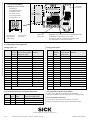
4. Pinbelegungen/Pin Assignments
Leitung/cable “I/O“
Signal Pin Pin Schnittstelle
Buchse Stecker (Steckerhaube) Interface
Socket Plug (cover hood)
DC 24 V 1 – –
IN 1 2 2 Digital input
Sensor 3 3 Digital input
Result 1 4 4 Digital output
GND 5 5 Ground
IN 0 6 6 Digital input
IN 2 7 7 Digital input
Result 2 8 8 Digital output
INGND 9 9 Input ground
Result 3 10 10 Digital output
IN 3 11 11 Digital input
IN 4 12 12 Digital input
I2C SDA 13 –
I2C SCL 14 –
Result 4 15 15 Digital output
Shield Gehäuse/Housing
Feldbus-Module
Field bus modules
Cloning-Modul CMC400
1)
CMC400 Cloning Module
1)
E/A-Karte
I/O board
Basiskarte
Main board
SICK AG · Waldkirch · Germany · www.sick.com
8010872/T183/2009-02 · 5M/TR <PM 6.5> · VD · Printed in Germany · Subject to change without prior notice · The specified product features and technical data do not represent any guarantee · AftE6205sw
Leitung/cable “Data“
Signal Pin Pin Schnittstelle
Stecker Buchse (Haube) Interface
Plug Socket (hood)
DC 24 V 1 – –
RxD 2 2 Aux (RS 232)
TxD 3 3 Aux (RS 232)
Term 4 4 Termination 422/485
GND 5 – –
RD+ 6 6 Host (RS 422/485)
RD–/RxD 7 7 Host (RS 422,485/232)
TD+ 8 8 Host (RS 422,485)
TD–/TxD 9 9 Host (RS 422,485/232)
CAN_H 10 10 CAN bus
Reserved 11 11 –
CAN2_H 12 12 CAN bus 2
CAN2_L 13 13 CAN bus 2
Reserved 14 14 –
CAN_L 15 15 CAN bus
Shield Gehäuse/Housing
3-pol. Versorgungsleitung/ 3-pin power supply cable
Signal Ader Aderendhülse Steckerhaube (St./Bu.)
Core Ferrule Cover hood (plug/socket)
DC 24 V 1 rt/red Pin 1/Pin 1 (Power supply)
GND 2 sw/black Pin 5/Pin 5 (Ground)
Shield 3 gr/grey Gehäuse/Housing
Anschlussmodul CDM490
CDM49O Connection module
Anschluss der
Versorgungsleitungen
an Klemme 1 bis 6.
Connection of the
power supply cables
on Terminal 1 to 6
OUT
IN
Bei Bedarf: interner Anschluss der Versorgungsspannung
von Basiskarte an E/A-Karte (siehe unten)
If necessary: internal connection of the power supply
from main board to I/O board (see below)
Vom Anwender bei Bedarf zu verdrahten:
V
S
, Klemme 29 (Basiskarte) auf Klemme 51 (E/A-Karte).
GND wird automatisch über die kälteresistente Leitung gebrückt.
To be connected if necessary:
V
S
, terminal 29 (main board) to terminal 51 (I/O board).
GND is automatically connected via the cold-resistent cable.
(von Stromver-
sorgung/from
power supply)
(zum Scanner/
to scanner)
-
 1
1
-
 2
2


SICK Cold-resistent cables no. 2030065/no. 2049613/no. 2031034 for CLV480, CLV/X490 Bar Code Scanner Mounting instructions
- Typ
- Mounting instructions
in anderen Sprachen
Verwandte Artikel
-
SICK CDM490 -0001 Connection Module Bedienungsanleitung
-
-
-
-
-
-
-
-
-