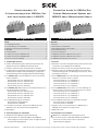
SICK Connection hoods for VMS4xx/5xx Volume Measurement System and LMS400 Laser Measurement Sensor Mounting instructions
- Typ
- Mounting instructions

© SICK AG · Germany · All rights reserved · Subject to change without notice · Irrtümer und Änderungen vorbehalten 1 # 128010817/X603/2013-03
Steckerhauben für
Volumenmesssystem VMS4xx/5xx
und Lasermesssensor LMS400
Inhalt
1. Produkteigenschaften .................................................................... 1
2. Voraussetzungen zur Installation .................................................. 2
3. Montage und elektrische Installation ........................................... 2
4. Massbild ......................................................................................... 2
5. Anschlusspläne .............................................................................. 3
5.1 Volumenmesssystem VMS410/510 .......................................... 3
5.2 Volumenmesssystem VMS420/520 .......................................... 8
5.3 Lasermesssensor LMS400 ....................................................... 11
1. Produkteigenschaften
■ Erfüllen durch Abdeckung der elektrischen Anschlüsse des
VMS4xx/5xx oder des LMS400 die Schutzart IP 65
■ Einfacher Anschluss durch vorkonfektionierte Leitungen
■ Zur Anpassung an vorhandene Anschlusstechnik verschiedene
Ausführungen verfügbar: M-Verschraubungen, 5-polige M12-
Steckverbindungen oder 15-polige D-Sub-Steckverbindungen
■ Für VMS410/510 ein Steckerhauben-Set mit je einer Stecker-
haube erforderlich:
- Steckerhauben-Set 1 (Nr. 2030439) oder
- Steckerhauben-Set 2 (Nr. 2034152) oder
- Steckerhauben-Set 3 (Nr. 2034153) oder
- Steckerhauben-Set 4 (Nr. 2034154)
■ Für VMS420/520 (Master/Slave) ein Steckerhauben-Set mit je
zwei Steckerhauben erforderlich:
- Steckerhauben-Set 5 (Nr. 2031364) oder
- Steckerhauben-Set 6 (Nr. 2031365) oder
- Steckerhauben-Set 7 (Nr. 2031366) oder
- Steckerhauben-Set 8 (Nr. 2031399)
■ Für LMS400 (Einzelgerät) erforderlich:
- Steckerhaube Nr. 2030439 oder
- Steckerhaube Nr. 2030535
■ Unterstützt den schnellen Tausch eines VMS4xx/5xx oder
LMS400 vor Ort durch Parameter-Cloning-Funktion
■ Wartungsfrei
2. Voraussetzungen zur Installation
■ VMS4xx/5xx oder LMS400 mit Betriebsanleitung
■ Für Steckerhaube Nr. 2030439 (VMS4xx/5xx/LMS400):
- Freier Zugang zur internen Buchse „AUX“ für Zugriff auf Gerät
zur Parametrierung/Diagnose
MontagMontag
MontagMontag
Montag
eanleitungeanleitung
eanleitungeanleitung
eanleitung
InsIns
InsIns
Ins
tallation Installation Ins
tallation Installation Ins
tallation Ins
trtr
trtr
tr
uctionsuctions
uctionsuctions
uctions
Contents
1. Features .......................................................................................... 1
2. Prerequisites for Installation ......................................................... 2
3. Assembling and Electrical Installing ............................................. 2
4. Dimensional Drawing ..................................................................... 2
5. Connection diagrams ..................................................................... 3
5.1 VMS410/510 Volume Measurement System ........................... 3
5.2 VMS420/520 Volume Measurement System ........................... 8
5.3 LMS400 Laser Measurement Sensor ...................................... 11
1. Features
■ Fulfillment of enclosure rating IP 65 with hood for the electrical
connections on the VMS4xx/5xx or LMS400.
■ Simplify the electrical connection using pre-fabricated cables.
■ Different versions are available depending on the connection
method: M-cable glands, 5-pin M12-plug connections or 15-pin
D Sub plug connections.
■ For the VMS410/510 one of the following connection hood sets,
each with 1 connection hood, is required:
- Connection hood set 1 (no. 2030439) or
- Connection hood set 2 (no. 2034152) or
- Connection hood set 3 (no. 2034153) or
- Connection hood set 4 (no. 2034154)
■ For the VMS420/520 (master/slave) one of the following con-
nection hood sets, each with 2 connection hoods, is required:
- Connection hood set 5 (no. 2031364) or
- Connection hood set 6 (no. 2031365) or
- Connection hood set 7 (no. 2031366) or
- Connection hood set 8 (no. 2031399)
■ For the LMS400 (stand-alone) the following is required:
- Connection hood no. 2030439 or
- Connection hood no. 2030535
■ Supports quick, on-site replacement of a VMS4xx/5xx or
LMS400 due to parameter cloning function.
■ Maintenance-free.
2. Prerequisites for Installation
■ VMS4xx/5xx or LMS400 with operating instructions.
■ For connection hood no. 2030439 (VMS4xx/5xx/LMS400):
- Free acces to internal “AUX“ socket is required for
parameterization/diagnosis
Connection hoods for VMS4xx/5xx
Volume Measurement System and
LMS400 Laser Measurement Sensor

© SICK AG · Germany · All rights reserved · Subject to change without notice · Irrtümer und Änderungen vorbehalten2 # 12 8010817/X603/2013-03
- Parametrierleitungen Nr. 2031372 und Nr. 2014054
- Schraubendreher für TORX-Schrauben T10
■ Für Steckerhauben-Set 3, 4, 7 oder 8:
Parametrierleitung Nr. 2014054
■ Innensechskantschlüssel, SW 3 mm
Hinweis:
In der Grundeinstellung (Auslieferungszustand) ist die Parameter-
Cloning-Funktion der Steckerhaube deaktiviert.
Mit dem Drehschalter S2 kann die Funktion aktiviert werden.
1. Versorgungsspannung für das VMS4xx/5xx oder LMS400
ausschalten.
2. Deckel der Steckerhaube (Abb. 1) durch Lösen der vier Schrau-
ben entfernen.
3. Schalter S2 (Abb. 4 oben, Seite 4) in die Stellung „F“ bringen
(Stellung „0“ = Funktion deaktiviert).
4. Deckel wieder befestigen und Versorgungsspannung einschalten.
3. Montage und elektrische Installation
■ Um den Kurzschluss-/Überlastungsschutz der Anschlussleitun-
gen sicherzustellen, sind die Adern der Versorgungsleitungen
mit folgenden Sicherungen zu schützen:
- Leitungen mit M12-Steckverbindungen: 4 A
- Leitungen mit D-Sub-Steckverbindungen: 2 A
Hierbei sind die gültigen Normen einzuhalten.
■ Für die korrekte Funktion der Steckerhaube darf der über die
Haube geführte Summenstrom für die Lichtschranke (Lesetakt)
und den Inkrementalgeber 600 mA nicht überschreiten.
Steckerhauben am Gerät vorsichtig so aufsetzen, dass die
vorstehenden 15-poligen Steckverbindungen in die Steck-
verbindungen des Gerätes greifen. Steckerhauben mit beiden
Innensechskantschrauben am Gerät befestigen.
Für VMS4xx/5xx: Abdeckung für Anschluss „FSI“ entfernen.
Steckerhaube Nr. 2030439: Steckerhaube öffnen (TORX-
Schrauben) und Verdrahtung gemäß im Deckel angebrachten
Belegungsplan spannungsfrei an den Klemmen vornehmen.
Leitungen über die vier M-Verschraubungen nach empfohlener
Belegung (Aufdruck) einführen. Für IP 65 nicht verwendete
M-Verschraubungen mit Blindstopfen versehen.
Steckerhauben zwischen Master und Slave gemäß Anschluss-
plänen (siehe Kapitel 5) miteinander verbinden.
Geräte mit externer Peripherie (Stromversorgung, Trigger, Tacho,
Host) gemäß Anschlussplänen verbinden.
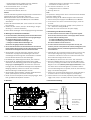
4. Massbild
- Configuration cables no. 2031372 and no. 2014054
- Screw driver for TORX screws T10
■ For connection hood set 3, 4, 7 or 8:
- Configuration cable no. 2014054
■ Allen key, SW 3 mm
Note:
The parameter cloning function of the connection hood is disabled
by factory default setting.
Parameter cloning can be enabled using the revolver switch S2.
1. Switch off the power supply for the VMS4xx/5xx or LMS400.
2. To remove the cover of the connection hood (Fig. 1), loose the
4 screws.
3. Set the switch S2 (on top of Fig. 4, Page 4) to the position “F“
(“0“ = Parameter cloning disabled).
4. Re-attach the cover and switch on the power supply.
3. Assembling and Electrical Installing
■ To ensure that the connection cables are protected against
short-circuits/overload, the wires of the supply cables must be
protected with the following fuses:
- for cables with M12 plug connections: 4 A
- for cables with D Sub plug connections: 2 A
The valid standards must be observed.
■ To ensure that the connection hood operates correctly, the
summary current of the photoelectric switch (reading pulse) and
the incremental encoder, routed through the hood, must not
exceed 600 mA.
Carefully place the connection hood on the device in such a way
that the protruding 15-pin plug connections fit into the plug
connections of the device. Secure the connection hoods to the
device with both hexagon-socket screws.
For VMS4xx/5xx: Remove the cover of the “FSI“ connection.
Hood no. 2030439: Open the connection hood (TORX screws)
and carry out wiring in accordance with the terminal connection
diagram in the cover (with the power supply switched off). Insert
the cables via the four M cable glands in accordance with the
recommended assignment (as printed). For IP 65, attach dummy
plugs to unused M cable glands.
Connect the connection hoods between the master and slave in
accordance with the connection diagrams (see Chapter 5).
Connect devices to the external peripherals (power supply,
trigger, tacho, host) in accordance with the connection diagrams.
4. Dimensional Drawing
Alle Abmessungen
in mm (inch)
All dimensions
in mm (inch)
129
(5)
29
(1.14)
49
(1.93)
26
(1.02)
Abb. 1: Massbild der Steckerhaube mit den größten Abmessungen/Fig. 1: Dimensional drawing of the connection hood with the highest dimensions
Schrauben des
Deckels
Cover screws

© SICK AG · Germany · All rights reserved · Subject to change without notice · Irrtümer und Änderungen vorbehalten 3 # 128010817/X603/2013-03
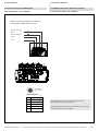
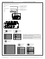
M-Verschraubungen/M12-Steckverbindung
M-cable glands/M12 plug connection
Power IN (DC 24 V)/
CAN IN
Host (RS 232/422)
Trigger
Tacho
„Power/CAN OUT“
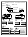
Abb. 2: VMS410/510: Steckerhauben-Set 1 (Nr. 2030439)/Fig. 2: VMS410/510: Connection hood set 1 (no. 2030439)
PIN Signal
1 Shield
2 DC +24 V
30 V
4 CAN_H
5 CAN_L
5-pol. Buchse/
5-pin socket
Steckerhauben-Set 1 (Nr. 2030439):
Connection Hood Set 1 (No. 2030439):
5. Anschlusspläne
5.1 Volumenmesssystem VMS410/510
5. Connection diagrams
5.1 VMS410/510 Volume Measurement System
Klemmenbelegungen und Schalterstellungen auf der
Anschlusskarte siehe Abb. 3, Seite 4.
Terminal assignment and meaning of switch positions on the
connection board see Fig. 3, Page 4.

© SICK AG · Germany · All rights reserved · Subject to change without notice · Irrtümer und Änderungen vorbehalten4 # 12 8010817/X603/2013-03
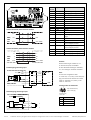
Steckerhaube/Connection Hood No. 2030439 (Master):
Abb. 3: VMS4xx/5xx: Klemmenbelegung für Steckerhaube Nr. 2030439/Fig. 3: VMS4xx/5xx: Terminal assignment of connection hood no. 2030439
Klemme Signal Anschluss/Connection
Terminal
1 GND_HEAT GND Heizung/heating
2 +24 V Versorgungsspannung/power
3 GND Ground
4 CAN_H CAN-Bus, High
5 CAN_L CAN-Bus, High
6 T+ Host (RS-422)
7 T–/TxD Host (RS-422/RS-232)
8 R+ Host (RS-422)
9 R–/RxD Host (RS-422/RS-232)
10 GND Ground
11 +24 V* Sensor
12 SGND Sensor-Ground
13 Sensor_ 3 Schalteingang/Switching input 3
Trigger
14 +24 V* Sensor
15 SGND Sensor-Ground
16 Sensor_2 Schalteingang/Switching input 2
Inkrementalgeber/Encoder
17 Sensor_4 Schalteingang/Switching input 4
Inkrementalgeber/Encoder
18 GND Ground
19 Result_1 Schaltausgang/Switching output 1
20 Result_2 Schaltausgang/Switching output 2
VMD/
LMS
400
Datenschnittstelle/Data interface RS-232
Datenschnittstelle/Data interface RS-422
Schalteingang/Switching input
Schaltausgang/Switching output
Sensor
IN GND
GND
GND
GND
OUT
2k6
1
3
9
5
V
S
V
S
V
S
V
S
CLV
SGND
GND
Result X
Fuse
Y
R
L
V
S
5
Logic
Temperature
sensor
Hinweis:
Parametrierleitung Nr. 2031372, 3 m,
an Stecker AUX (ST3) anschließen.
PC über Nullmodemleitung Nr. 2014054,
3 m, mit Leitung Nr. 2031372 verbinden.
Note:
Connect the configuration cable
no. 2031372, 3 m (9.8 ft), to the AUX (ST3)
plug. Connect the PC with the null modem
cable no. 2014054, 3 m (9.8 ft), to the
cable no. 2031372.
Leitung/Cable No. 2031372:
9-pol. D-Sub-Stecker/
9-pin D Sub plug
VMD/
LMS
400
VMD/LMS400
VMD/LMS400
RxD
TxD
GND
TxD
RxD
GND
Host
R+
R–
T+
T–
GND
GND
Host
T+
R+
T–
R–
5
1
9
6
Frontansicht/
front view
PIN Signal
2 RxD (RS-232)
3 TxD (RS-232)
5 GND

© SICK AG · Germany · All rights reserved · Subject to change without notice · Irrtümer und Änderungen vorbehalten 5 # 128010817/X603/2013-03
Steckerhauben-Set 2 (Nr. 2034152):
M12-Steckverbindungen/M12 plug connections
Leitung/cable „Power/CAN“,
No. 6021175, 10 m (32.8 ft),
offenes Ende/open end
Power IN (DC 24 V)/
CAN IN
Host (RS 232/422)
Trigger
Tacho
„Power/CAN OUT“
Abb. 4: VMS410/510: Steckerhauben-Set 2 (Nr. 2034152)/Fig. 4: VMS410/510: Connection hood set 2 (no. 2034152)
PIN Signal
1 Shield
2 DC +24 V
30 V
4 CAN_H
5 CAN_L
5-pol. Buchse/
5-pin socket
„Power/CAN IN“
PIN Signal
1 Shield
2 DC +24 V
30 V
4 CAN_H
5 CAN_L
5-pol. Stecker/
5-pin plug
„Host“
PIN Signal
1 TxD (RS-232), Terminal
2 RxD (RS-232), Terminal
3 R+ (RS-422), Host
4 R–/RxD (RS-422/RS-232), Host
5 T+ (RS-422), Host
6 T–/TxD (RS-422/RS-232), Host
7 GND
8 Shield
8-pol. Stecker/
8-pin plug
4-pol. Buchse/
4-pin socket
„Tacho“
4-pol. Buchse/
4-pin socket
„Trigger“
PIN Signal
1L+
2Q
3M
4Q
PIN Signal
1 DC +24 V
2A
3 GND
4B
Connection Hood Set 2 (No. 2034152):
Leitung/cable „Host“,
No. 6028420, 10 m (32.8 ft),
offenes Ende/open end
Pinbelegungen sowie Aderfarben für Anschlussleitungen mit
offenen Enden siehe Abb. 5, Seite 6.
Pin assignments as well as wire colour assignment for cables
with open ends see Fig. 5, Page 6.

© SICK AG · Germany · All rights reserved · Subject to change without notice · Irrtümer und Änderungen vorbehalten6 # 12 8010817/X603/2013-03
Stecker/Plug No. 6022083 („Tacho“, „Trigger“):
Abb. 5: VMS4xx/5xx: Pin-/Aderfarbenbelegung für Steckerhauben-Set 2 und 6/Fig. 5: Pin and core color assignment of connection hood set 2 and 6
4-pol. Stecker/
4-pin plug
„Tacho“
4-pol. Stecker/
4-pin plug
„Trigger“
PIN Signal
1L+
2Q
3M
4Q
PIN Signal
1 DC +24 V
2A
3 GND
4B
PIN Signal Farbe/Color
1 TxD (RS-232), Terminal Weiß/white
2 RxD (RS-232), Terminal Braun/brown
3 R+ (RS-422), Host Grün/green
4 R–/RxD (RS-422/RS-232), Host Gelb/yellow
5 T+ (RS-422), Host Grau/grey
6 T–/TxD (RS-422/RS-232), Host Rosa/pink
7 GND Blau/blue
8 Shield Rot/red
Leitung/Cable No. 6028420 („Host“):
Leitung/Cable No. 6021175 („Power/CAN IN“):
PIN Signal Farbe/Color
1 Shield –
2 DC +24 V Rot/red
3 0 V Schwarz/black
4 CAN_H Weiß/white
5 CAN_L Blau/blue
5-pol. Buchse/
5-pin socket
Hinweis:
Beschaltung der Datenschnittstellen und der digita-
len Ein- und Ausgänge siehe Abb. 3, Seite 4.
Note:
For connecting the data interfaces and the digital
inputs/outputs see Fig. 3, Page 4.

© SICK AG · Germany · All rights reserved · Subject to change without notice · Irrtümer und Änderungen vorbehalten 7 # 128010817/X603/2013-03
Abb. 6: VMS410/510: Steckerhauben-Set 3 und 4 (No. 2034153/No. 2034154)/Fig. 6: Connection hood set 3 and 4 (no. 2034153/no. 2034154)
Steckerhauben-Set 3 und Set 4/Connection Hood Set 3 and 4 (No. 2034153/No. 2034154):
Leitungen mit 15-pol. D-Sub-Steckverbindungen/
Cables with 15-pin D Sub plug connections
CDM 1
1 10
15
6
11
5
5 6
11
10
15
1
CDM490
Power (DC 24 V)
*)
Host (RS 232/422)
Trigger
Tacho
PIN Signal
1 DC +24 V
2 Sensor 3
3 Sensor 1
4 Result 1
5 GND
6 Sensor 2
7 Sensor 4
8 Result 2
9 SGND
10 Result 3
11 n. c.
12 n. c.
13 Result 20 mA
14 Analog-GND
15 Result 4
Housing Shield
PIN Signal
1 DC +24 V
2 RxD (RS-232), Terminal
3 TxD (RS-232), Terminal
4 n. c.
5 GND
6 R+ (RS-422), Host
7 R–/RxD (RS-422/RS-232), Host
8 T+ (RS-422), Host
9 T–/TxD (RS-422/RS-232), Host
10 CAN_ H
11 n. c.
12 CAN2_H
13 CAN2_L
14 n. c.
15 CAN_L
Housing Shield
1 10
15
6
11
5
5 6
11
10
15
1
15-pol. D-Sub-Stecker/
15-pin D Sub plug
15-pol. D-Sub-Buchse/
15-pin D Sub socket
*) Set 4:
mit zusätzlichem/with additional CMP490:
AC 100 ... 250 V, 50 ... 60 Hz.
Verdrahtung des CDM490:
siehe Betriebsanleitung Nr. 8010005.
For wiring the CDM490:
see operating instructions no. 8010005.
Parametrierleitung Nr. 2014054,
3 m, an Stecker AUX im CDM490
anschließen.
Connect the configuration cable
no. 2014054, 3 m (9.8 ft), to the
AUX plug in the CDM490.
Steckerhauben-Set 3: ohne Netzteil CMP490
Steckerhauben-Set 4: mit Netzteil CMP490
Connection Hood Set 3: without CMP490 Power Supply Unit
Connection Hood Set 4: with CMP490 Power Supply Unit
Leitung/cable 2 (3 m /9.8 ft)
Leitung/cable 1 (3 m /9.8 ft)
Leitung/cable 1Leitung/cable 2

© SICK AG · Germany · All rights reserved · Subject to change without notice · Irrtümer und Änderungen vorbehalten8 # 12 8010817/X603/2013-03
Steckerhaube/Connection Hood No. 2030439:
M-Verschraubungen/M12-Steckverbindung
M-cable glands/M12 plug connection
Steckerhaube/Connection Hood No. 2030440:
M12-Steckverbindungen/M12 plug connections
Master
(VMD)
Slave
(VMD)
Leitung/cable „Power/CAN“,
No. 6021165, 3 m (9.8 ft)
M12-Steckverbindungen/
M12 plug connections
Leitung/cable „FSI“,
No. 2030451, 3 m (9.8 ft)
RJ-45-Stecker/plugs
Power IN (DC 24 V)/
CAN IN
Host (RS 232/422)
Trigger
Tacho
„Power/CAN OUT“
Abb. 7: VMS420/520: Steckerhauben-Set 5 (Nr. 2031364)/Fig. 7: VMS420/520: Connection hood set 5 (no. 2031364)
PIN Signal
1 Shield
2 DC +24 V
30 V
4 CAN_H
5 CAN_L
„Terminal Interface“
PIN Signal
1 TxD (RS-232)
2 RxD (RS-232)
7 GND
8 Shield
„Power/CAN IN“
PIN Signal
1 Shield
2 DC +24 V
30 V
4 CAN_H
5 CAN_L
5-pol. Stecker/
5-pin plug
8-pol. Stecker/
8-pin plug
5-pol. Buchse/
5-pin socket
5.2 Volumenmesssystem VMS420/520
Steckerhauben-Set 5 (Nr. 2031364):
5.2 VMS420/520 Volume Measurement System
Connection Hood Set 5 (No. 2031364):
Klemmenbelegungen und Schalterstellungen auf der
Anschlusskarte des Masters siehe Abb. 3, Seite 4.
Terminal assignment and meaning of switch positions on the
connection board of the master see Fig. 3, Page 4.

© SICK AG · Germany · All rights reserved · Subject to change without notice · Irrtümer und Änderungen vorbehalten 9 # 128010817/X603/2013-03
Steckerhauben-Set 6 (Nr. 2031365):
Steckerhaube/Connection Hood No. 2030396:
M12-Steckverbindungen/M12 plug connections
Steckerhaube/Connection Hood No. 2030440:
M12-Steckverbindungen/M12 plug connections
Master (VMD) Slave (VMD)
Leitung/cable „Power/CAN“,
No. 6021175, 10 m (32.8 ft),
offenes Ende/open end
M12-Steckverbindungen/
M12 plug connections
Leitung/cable „FSI“,
No. 2030451, 3 m (9.8 ft)
RJ-45-Stecker/plugs
Power IN (DC 24 V)/
CAN IN
Host (RS 232/422)
Trigger
Tacho
„Power/CAN OUT“
Abb. 8: VMS420/520: Steckerhauben-Set 6 (Nr. 2031365)/Fig. 8: VMS420/520: Connection hood set 6 (no. 2031365)
PIN Signal
1 Shield
2 DC +24 V
30 V
4 CAN_H
5 CAN_L
„Terminal Interface“
PIN Signal
1 TxD (RS-232)
2 RxD (RS-232)
7 GND
8 Shield
„Power/CAN IN“
PIN Signal
1 Shield
2 DC+24 V
30 V
4 CAN_H
5 CAN_L
5-pol. Stecker/
5-pin plug
8-pol. Stecker/
8-pin plug
5-pol. Buchse/
5-pin socket
Leitung/cable „Host“,
No. 6028420, 10 m (32.8 ft)
Offenes Ende/open end
„Power/CAN IN“
PIN Signal
1 Shield
2 DC +24 V
30 V
4 CAN_H
5 CAN_L
5-pol. Stecker/
5-pin plug
„Host“
PIN Signal
1 TxD (RS-232), Terminal
2 RxD (RS-232), Terminal
3 R+ (RS-422), Host
4 R–/RxD (RS-422/RS-232), Host
5 T+ (RS-422), Host
6 T–/TxD (RS-422/RS-232), Host
7 GND
8 Shield
8-pol. Stecker/
8-pin plug
4-pol. Buchse/
4-pin socket
„Tacho“
4-pol. Buchse/
4-pin socket
„Trigger“
PIN Signal
1L+
2Q
3M
4Q
PIN Signal
1 DC +24 V
2A
3 GND
4B
Leitung/cable „Power/CAN“,
No. 6021165, 3 m (9.8 ft)
Connection Hood Set 6 (No. 2031365):
Pinbelegungen sowie
Aderfarben für Anschluss-
leitungen mit offenen Enden
siehe Abb. 5, Seite 6.
For pin assignment as well
as wire colour assignment
for cables with open ends
see Fig. 5, Page 6.

© SICK AG · Germany · All rights reserved · Subject to change without notice · Irrtümer und Änderungen vorbehalten10 # 12 8010817/X603/2013-03
Abb. 9: VMS420/520: Steckerhauben-Set 7 und 8 (No. 2031366/No. 2031399)/Fig. 9: Connection hood set 7 and 8 (no. 2031366/no. 2031399)
Steckerhauben-Set 7 und Set 8/Connection Hood Set 7 and 8 (No. 2031366/No. 2031399):
Steckerhaube/Connection Hood No. 2030535:
Leitungen mit 15-pol. D-Sub-Steckverbindungen/
Cables with 15-pin D Sub plug connections
Steckerhaube/Connection Hood No. 2030494:
Leitung mit 15-pol. D-Sub-Steckverbindung/
Cable with 15-pin D Sub plug connection
Master (VMD) Slave
(VMD)
Leitung/cable „FSI“,
No. 2030451, 3 m (9.8 ft)
RJ-45-Stecker/plugs
CDM 1 CDM 2
1 10
15
6
11
5
5 6
11
10
15
1
CDM490
1 10
15
6
11
5
5 6
11
10
15
1
CDM490
Power (DC 24 V)
*)
Host (RS 232/422)
Trigger
Tacho
Power (DC 24 V)
*)
PIN Signal
1 DC +24 V
2 Sensor 3
3 Sensor 1
4 Result 1
5 GND
6 Sensor 2
7 Sensor 4
8 Result 2
9 SGND
10 Result 3
11 n. c.
12 n. c.
13 Result 20 mA
14 Analog-GND
15 Result 4
Housing Shield
PIN Signal
1 DC +24 V
2 RxD (RS-232), Terminal
3 TxD (RS-232), Terminal
4 n. c.
5 GND
6 R+ (RS-422), Host
7 R–/RxD (RS-422/RS-232), Host
8 T+ (RS-422), Host
9 T–/TxD (RS-422/RS-232), Host
10 CAN_ H
11 n. c.
12 CAN2_H
13 CAN2_L
14 n. c.
15 CAN_L
Housing Shield
1 10
15
6
11
5
PIN Signal
1 DC +24 V
2 RxD (RS-232), Terminal
3 TxD (RS-232), Terminal
4 n. c.
5 GND
6 R+ (RS-422), Host
7 R–/RxD (RS-422/RS-232), Host
8 T+ (RS-422), Host
9 T–/TxD (RS-422/RS-232), Host
10 CAN_ H
11 n. c.
12 CAN2_H
13 CAN2_L
14 n. c.
15 CAN_L
Housing Shield
5 6
11
10
15
1
15-pol. D-Sub-Stecker/
15-pin D Sub plug
5 6
11
10
15
1
15-pol. D-Sub-Stecker/
15-pin D Sub plug
15-pol. D-Sub-Buchse/
15-pin D Sub socket
*) Set 8:
mit zusätzlichem/
with additional CMP490:
AC 100 ... 250 V,
50 ... 60 Hz
Verdrahtung des CDM490:
siehe Betriebsanleitung
Nr. 8010005.
For wiring the CDM490:
see operating instructions
no. 8010005.
Parametrierleitung Nr. 2014054,
3 m, an Stecker AUX im CDM490
anschließen.
Connect the configuration cable
no. 2014054, 3 m (9.8 ft), to the
AUX plug in the CDM490.
Leitung/cable 2 (3 m /9.8 ft)
Leitung/cable 1 (3 m /9.8 ft)
Leitung/cable 3 (3 m /9.8 ft)
Leitung/cable 1Leitung/cable 2 Leitung/cable 3

© SICK AG · Germany · All rights reserved · Subject to change without notice · Irrtümer und Änderungen vorbehalten 11 # 128010817/X603/2013-03
5.3 Lasermesssensor LMS400
M-Verschraubungen/M-cable glands
LMS400
Power IN (DC 24 V)/
CAN
Serial interface
Output
Input
Abb. 10: LMS400: Klemmenbelegung für Steckerhaube Nr. 2030439/Fig. 10: LMS 400: Terminal assignment of connection hood no. 2030439
Steckerhaube Nr. 2030439:
Hinweis:
Parametrierleitung Nr. 2031372, 3 m,
an Stecker AUX (ST3) anschließen.
PC über Nullmodemleitung Nr. 2014054, 3 m, mit
Leitung Nr. 2031372 verbinden.
Note:
Connect the configuration cable no. 2031372,
3 m (9.8 ft), to the AUX (ST3) plug.
Connect the PC with the null modem cable
no. 2014054, 3 m (9.8 ft), to the cable no. 2031372.
Leitung/cable No. 2031372:
9-pol. D-Sub-Stecker/
9-pin D Sub plug
Beschaltung der Datenschnittstellen und der digita-
len Ein- und Ausgänge siehe Abb. 3, Seite 4.
For connecting the data interfaces and the digital
inputs/outputs see Fig. 3, Page 4.
Kl./Terminal Signal Anschluss/Connection
1 GND_HEAT GND Heizung/heating
2 +24 V Versorgungsspannung/power
3 GND Ground
4 CAN_H CAN-Bus, High
5 CAN_L CAN-Bus, High
6 T+ Host (RS-422)
7 T–/TxD Host (RS-422/RS-232)
8 R+ Host (RS-422)
9 R–/RxD Host (RS-422/RS-232)
10 GND Ground
11 +24 V* Sensor
12 SGND Sensor-Ground
13 Sensor_ 3 Schalteingang/Switching input 3
Trigger
14 +24 V* Sensor
15 SGND Sensor-Ground
16 Sensor_2 Schalteingang/Switching input 2
Inkrementalgeber/Encoder
17 Sensor_4 Schalteingang/Switching input 4
Inkrementalgeber/Encoder
18 GND Ground
19 Result_1 Schaltausgang/Switching output 1
20 Result_2 Schaltausgang/Switching output 2
5.3 LMS400 Laser Measurement Sensor
Connection Hood No. 2030439:
5
1
9
6
PIN Signal
2 RxD (RS-232)
3 TxD (RS-232)
5 GND
Frontansicht/
front view

© SICK AG · Germany · All rights reserved · Subject to change without notice · Irrtümer und Änderungen vorbehalten12 # 12 8010817/X603/2013-03
Abb. 11: LMS400: Pinbelegung für Steckerhaube Nr. 2030535/Fig. 11: LMS400: Pin assignment of connection hood no. 2030535
Steckerhaube Nr. 2030535:
Connection Hood No. 2030535:
SICK AG · Waldkirch · Germany · www.sick.com · 8010817/X603/2013-03 · MT_8M <PM 6.5> · Printed in Germany · Subject to change without prior notice · AftE39sw
LMS400
1 10
15
6
11
5
5 6
11
10
15
1
CDM490
Power (DC 24 V)
*)
Host (RS 232/422)
Trigger
Tacho
PIN Signal
1 DC +24 V
2 RxD (RS-232), Terminal
3 TxD (RS-232), Terminal
4 n. c.
5 GND
6 R+ (RS-422), Host
7 R–/RxD (RS-422/RS-232), Host
8 T+ (RS-422), Host
9 T–/TxD (RS-422/RS-232), Host
10 CAN_ H
11 n. c.
12 CAN2_H
13 CAN2_L
14 n. c.
15 CAN_L
Housing Shield
5 6
11
10
15
1
15-pol. D-Sub-Stecker/
15-pin D Sub plug
*) mit zusätzlichem/with additional CMP490:
AC 100 ... 250 V, 50 ... 60 Hz.
Verdrahtung des CDM490:
siehe Betriebsanleitung Nr. 8010005.
For wiring the CDM490:
see operating instructions no. 8010005.
Parametrierleitung Nr. 2014054, 3 m,
an Stecker AUX im CDM490 anschließen.
Connect the configuration cable no. 2014054,
3 m (9.8 ft), to the AUX plug in the CDM490.
Beschaltung der Datenschnittstellen und der digita-
len Ein- und Ausgänge siehe Abb. 3, Seite 4.
For connecting the data interfaces and the digital
inputs/outputs see Fig. 3, Page 4.
Leitungen mit 15-pol. D-Sub-Steckverbindungen/
Cables with 15-pin D Sub plug connections
15-pol. D-Sub-Buchse/
15-pin D Sub socket
1 10
15
6
11
5
PIN Signal
1 DC +24 V
2 Sensor 3
3 Sensor 1
4 Result 1
5 GND
6 Sensor 2
7 Sensor 4
8 Result 2
9 SGND
10 Result 3
11 n. c.
12 n. c.
13 Result 20 mA
14 Analog-GND
15 Result 4
Housing Shield
Leitung/cable 2 (3 m /9.8 ft)
Leitung/cable 1 (3 m /9.8 ft)
Leitung/cable 1Leitung/cable 2
-
 1
1
-
 2
2
-
 3
3
-
 4
4
-
 5
5
-
 6
6
-
 7
7
-
 8
8
-
 9
9
-
 10
10
-
 11
11
-
 12
12


SICK Connection hoods for VMS4xx/5xx Volume Measurement System and LMS400 Laser Measurement Sensor Mounting instructions
- Typ
- Mounting instructions
Verwandte Artikel
-
SICK CDM490 -0001 Connection Module Bedienungsanleitung
-
-
-
-
-
-
-
-
-