RCS VLZ-6120A-6240A-6480A-6600A Bedienungsanleitung
- Kategorie
- Audioverstärker
- Typ
- Bedienungsanleitung

OPERATING INSTRUCTIONS / BEDIENUNGSANLEITUNG
- ENGLISH
- DEUTSCH
VLZ-SERIES
6-ZONE VARIO-LINE
VLZ-6120 A
VLZ-6240 A
VLZ-6360 A
VLZ-6480 A
VLZ-6600 A

2
Electromagnetic compatibility and low-voltage guidelines: RCS leaves all devices and products, which are subject to the CE guidelines by certied test laboratories test.
By the fact it is guaranteed that you may sell our devices in Germany and in the European Union domestic market without additional checks.
Elektromagnetische Verträglichkeit und Niederspannungsrichtlinien: RCS läßt alle Geräte und Produkte, die den CE-Richtlinien unterliegen durch zertizierte Prüabors
testen. Dadurch ist sichergestellt, dass Sie unsere Geräte in Deutschland und im EU-Binnenmarkt ohne zusätzliche Prüfungen verkaufen dürfen.
AUSPACKEN UND KONTROLLE DES PRODUKTS
Bitte überprüfen Sie das Gerät sofort auf evtl. Transportschä-
den. Jedes RCS Produkt wird vor dem Verpacken sorgfältig
überprüft und in einem speziell dafür vorgesehenen Karton
geliefert.
Alle Transportschäden müssen sofort bei der Transport-
rma reklamiert werden!
Rücksendung: Wenn es nötig sein sollte ein defektes Gerät
zurückzusenden, nehmen Sie bitte Kontakt mit Ihrem Händ-
ler auf. Bitte versenden sie alle Rücksendungen in der Origi-
nalverpackung.
INSPECTION AND INVENTORY OF THE PRODUCT
Check unit carefully for damage which may have occurred
during transport. Each RCS product is carefully inspected
at the factory and packed in a special carton for safe
transport.
Notify the freight carrier immediately if you observe any
damage to the shipping carton or product!
Return: Repack the unit in the carton and await inspection
by the carrier’s claim agent. Notify your dealer of the pending
freight claim. Returning your unit for service or repairs.
Should your unit require service, contact your dealer.
WICHTIGE SICHERHEITSHINWEISE
Bitte lesen Sie die Sicherheitsanweisungen, bevor Sie
das Gerät in Betrieb nehmen.
1. Installation nach folgenden Richtlinien:
• Stellen Sie das Gerät immer auf eine ebene und stabile
Unteräche.
• Wählen Sie eine trockene Umgebung und vermeiden Sie
Aufstellungsorte mit geringer Luftzufuhr.
• Vermeiden Sie die direkte Nähe zu Heizungen und ande-
ren Hitzequellen.
• Bei Einbau in einen 19“ Gestellschrank ordnen Sie die
Geräte so an, daß eine ausreichende Belüftung gewähr-
leistet wird.
2. Bitte beachten Sie folgendes, wenn Sie das Gerät
anschließen:
• Um Bedienfehler zu vermeiden, lesen Sie bitte zuerst die
Anleitung sorgfältig.
• Önen Sie niemals das Gehäuse, ohne vorher den Netz-
stecker zu ziehen.
• Schließen Sie das Gerät nur an 230 V Netzspannung und
an die 24 V Notstromversorgung (DC).
SAFETY INSTRUCTION
Please read all safety instructions before operating the
Device.
1. Installation according to the following guidelines:
• Install the device always on a at and even surface.
• The device should not be exposed to damp or wet
surroundings. Please keep away from water.
• Please avoid using the device near heat sources, such as
radiators or other devices which produce heat.
• To install the device in a 19” rack please note that the ap-
pliance should be situated, that the location or position
does not interfere with an adequate ventilation.
2. Keep in mind the following when connecting the
device:
• Connect the amplifier after reading the manuals.
• To prevent electric shock, do not open top cover.
• Connect only to 230 V and 24 V Emergency power (DC).
CAUTION / ACHTUNG
CAUTION: TO REDUCE THE RISK OF ELECTRIC SHOCK DO NOT REMOVE
COVER (OR BACK) NO USER-SERVICEABLE PARTS INSIDE REFER SER-
VICIING TO QUALIFIED PERSONNEL.
ACHTUNG: ZUR VERMEIDUNG VON STROMSCHLÄGEN GEHÄUSEAB-
DECKUNG ODER RÜCKSEITE NICHT ENTFERNEN. KEINE VOM BENUT-
ZER WARTENDEN TEILE IM INNEREN. WARTUNG NUR DURCH QUALIFI-
ZIERTEM PERSONAL.
SAFETY INSTRUCTIONS VLZ-SERIES

3
VLZ-SERIES CONTENTS
VLZ-6120 A / VLZ-6240 A / VLZ-6360 A / VLZ-6480 A / VLZ-6600 A
GENERAL REFERENCES / ALLGEMEINE HINWEISE
.......................................... 2
FEATURES / HAUPTMERKMALE
........................................................... 4
MOUNTING & COOLING / MONTAGE & KÜHLUNG
........................................... 5
VLZ-SERIES FRONT PANEL / FRONTANSICHT
..........................................6-7
VLZ-SERIES REAR VIEW / RÜCKANSICHT
........................................... 8-10
INSTALLATION OF ADDITIONAL MODULES / EINBAU VON ZUSATZMODULEN
.................11
FD-21 PILOTTONE-MODULE / PILOTTON-MODUL
..................................12
FM-30 ERROR MONITORING MODULE / FEHLER MONITORING-MODUL
..............14
FS-40 FREQUENCY SHIFT-MODULE / FREQUENZSHIFTER-MODUL
..................15
VLZ-SERIES SAMPLE APPLICATIONS / ANWENDUNGSBEISPIELE
....................16, 17
VLZ-SERIES PRIORITY FUNCTIONS / PRIORITÄTS FUNKTIONEN
..........................18
VLM-106/206 MICROPHONE DESK / MICROPHON-SPRECHSTELLE
....................19, 20
VLM-100 MICROPHONE DESK / MICROPHON-SPRECHSTELLE
.........................20
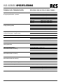
VLZ-SERIES SPECIFICATIONS / TECHNISCHE DATEN
....................................21
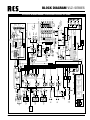
VLZ-SERIES BLOCK DIAGRAM / BLOCKSCHALTBILD
....................................22
NOTES / NOTIZEN
......................................................................23
CONTENTS / INHALT

4
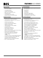
MAIN FEATURES
• Automatic variable speed fan
• Over current protection
• Over heating protection
• Load short circuit protection
• Built in l.P.F. ( Low pass lter ) circuit
• Output led indicator
• 6 Zone speaker output or all call
• Speaker attenuator per channel by 6 step
FURTHER FEATURES
• Input gain volume control per microphone
• Selective phantom power per microphone
• Din connecter for P.T.T. Microphone (VLM-100) input
• Rca jack for LINE 4, 5 input
• Rca jack for RECording output
• Connect for PRE-OUT/external AMP IN
• Equalizer per input channel
• Telephone PAGING and NIGHT RINGER
• 2- Or 4-tone chime
(switchable with jumper ms 1)
• Siren switachble to alarme tone
• Optional module connection
(CR-10, TP-10, CP-10, DM-10, CDP-10 M, CDR-10 RDS)
• Remote control for POWER ON/OFF
• SOFT START for battery power supply delay
• Remote control system by RJ45 connector
1. Digital message
2. Chime
3. Connection with up to 3 VLM-106/206 simultaneously
• Auto alert announcement and AUTO POWER "ON"
Connecting to digital message (DM-10)
(Message rst priority connecting with re alarm)
• Mic 1, 2, 3 priority selector switch
HAUPTMERKMALE
• Automatische Anpassung der Lüftergeschwindigkeit
• Kurzsschlußschutz
• Überhitzschutz
• Leerlaufschutz
• Low Pass Filter
• Ausgang LED- Pegel Anzeige
• 6 Lautsprecherkreise und Summe
• Lautstärkereglung pro Kreis in 6 Stufen
WEITERE MERKMALE
• MIC-Eingänge mit Gain-Regler ( Combo-Buchsen )
• Wahlweise Phantom-Power
• 7-pol DIN-Buchse für P.T.T. Microphon (VLM-100)
• Cinch-Buchsen für LINE-Eingänge 4,5
• Cinch-Buchse für REC Output,unsymm., 0 db
• PRE-OUT und AMP IN Klinkenbuchsen, 6,3 mm
• Für jeden Eingang Bass und Höhenregelung
• TEL-IN für PAGING IN und NIGHT RINGER
• Elektronischer 2- oder 4-Klanggong
(umstellbar mit Jumper MS 1 unter Leerblende)
• Sirene umschaltbar auf Alarmton
• Leerfeld für optionale Tonträgermodule
(CR-10, TP-10, CP-10, DM-10, CDP-10 M, CDR-10 RDS)
• Fernbedienung für POWER "ON/OFF"
• SOFT START
• Fernsteuerung über digitale Schnittstelle RJ45
1. Digitales Textmodul (Option)
2. Vorgong
3. Verbindung von mehreren VLM-106/206 gleichzeitig
• AUTO POWER "ON" und automatische Alarmdurchsage
über digitales Textmodul DM-10
(Priorität von Durchsage und Feueralarm möglich)
• Schalter für Priorität von MIC-1, 2 und 3
FEATURES VLZ-SERIES

5
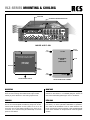
MOUNTING
Amplier racking size for VLZ-series are designed for stan-
dard 19˝ rack mounting with additional left, right bracket.
Please pay close attention to the cooling requirements.
COOLING
Never block the air vents in the sides makes enough space
line 44 mm of the amplier the following is gure of air-ow.
Check inside temperature of rack system so as not to be
more than 40°C for the stable operating in any case, we re-
commend you to install cooling fan additionally on the rear
panel of rack cabinet.
MONTAGE
Die Verstärker der VLZ-Serie sind mit seitlichen Befestigung-
winkeln für den Einbau in 19˝ Gestelle geeignet. Achten sie
aber darauf die Kühlungsönungen nicht zu verdecken.
KÜHLUNG
Blockieren sie nie die Luftönungen an den Seiten (min. 44
mm Raum), um einen optimalen Kühlluftuß zu gewährlei-
sten. Falls sie die Verstärker in ein 19"-Rack einbauen und
immer mit höchster Leistung arbeiten, sollte gegebenenfalls
in das Rack ebenfalls ein entsprechender Lüfter eingebaut
werden.
INSIDE AIRFLOW
IMPORTANT:Be sure rear of amplifier
is securely mounted to rack.
AMPLIFIER
(TOP VIEW)
4in(10cm)MIN
RACK
CABINET
NIM)mc6(ni4.2
RACK MOUNT SPACE
AIR FLOW IN RACK CABINET
AIR FLOW
EQUIPMENT
RACK
(SIDE VIEW)
BLOWER
AIR
FLOW
AIR
FLOW
BLOWER
DOOR
FRONT
OF RACK
PROTECTPROTECT FAULTFAULT
AUTOMATIC VARIABLE SPEED FAN
VLZ-6480
A.T.T 6 Zone Mixing Amplifier
SPEAKER ZONES & A.T.T
HEAT-SINK
VLZ-SERIES MOUNTING & COOLING

6
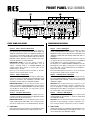
FRONTANSICHT VLZ-SERIE
1. MIC / LINE LEVEL
Regler: P.T.T 1 / EQ Regler
P.T.T 1 Regler für Lautstärke und EQ Regler für Tiefen
sowie Höheneinstellung des Eingang 1 und des P.T.T
REMOTE Eingang, (VLM-100) immer in Verbindung mit
"MASTER" Regler. Die LED Anzeige sollte nicht über "0"
ansteigen.
WICHTIG: Falls die Prioritätsfunktion aktiviert ist, können
nur Signale die auf dem Eingang 1 bzw. P.T.T REMOTE
(7-pol. DIN-Buchse) anliegen, empfangen werden.
Die Eingänge 4, 5, NIGHT RINGER, PAGING IN und alle
Modulsignale (außer DM-10) sind gesperrt, vorausgesetzt
der Jumper MS 2 (hinter Abdeckpaneel des Modulleer-
feldes) steht auf "SLAVE".
Diese Prioritätsfunktion besteht nicht , wenn der Schalter
der Sprechstelle (VLM-100) auf "SLAVE" steht.
Regler: R.M. 2 Volume / EQ Regler
Remote 2 Regler für Lautstärke und EQ Regler für Tie-
fen sowie Höheneinstellung des Eingang 2 und digitale
Sprechstellen (VLM-106/206) - immer in Verbindung mit
"MASTER" Regler.
WICHTIG: Falls die Priorität aktiviert ist, können nur Si-
gnale die auf dem Eingang 2 anliegen, empfangen wer-
den. Die Eingänge 4, 5, Night Ringer, Paging In und alle
Modulsignale (außer DM-10) sind gesperrt, vorausgesetzt
der Jumper MS 2 steht auf "SLAVE".
Regler: 3 Volume / EQ Regler 3
Regler 3 für Lautstärke und EQ Regler für Tiefen sowie
Höheneinstellung des Eingang 3 - immer in Verbindung
mit "MASTER" Regler.
WICHTIG: Falls die Priorität aktiviert ist, können nur Si-
gnale die auf dem Eingang 3 anliegen, empfangen wer-
den, vorausgesetzt der Jumper MS 2 steht auf "SLAVE".
2. LINE / LEVEL
Regler LINE LEVEL für Lautstärke und EQ Regler für Tie-
fen sowie Höheneinstellung der Eingänge 4 und 5 - im-
mer in Verbindung mit "MASTER" Regler.
PROTECTPROTECT FAULTFAULT
SPEAKER ZONES & A.T.T
VLZ-6480
6 ZONE MIXING AMPIFIER
A B F
FRONT PANEL VLZ-SERIES
1. MIC / LINE LEVEL
Control: P.T.T 1 Volume / EQ Control
P.T.T 1 volume control / EQ control let you adjust in-
put 1level and P.T.T remote (VLM-100) level. BASS and
TREBLE CONTROLS make you adjusted equalizer so
as to suit for surrounding usually, rst, position adjusted
should be set at "0" of LED indicator with two 0`clock of
MASTER volume. Second, you can increase input volu-
me to the position "0" of LED indicator.
IMPORTANT NOTE: In case the priority function is
activated, if you supply signal to MIC/LINE 1, then, all
signals including LINE 4, 5, PAGING RINGER and
module signals will be closed ,set Jumper MS 2 on the
FRONT PCB to "SLAVE".
But if you select switch of remote controller to "SLAVE",
signal of remote control will be cut-off.
Control: R.M. 2 / EQ Control
Remote 2 volume control / EQ control let you adjust input
2 level and remote controller (VLM-106/206) level. This
always in connection with “MASTER” controller. Bass
and treble controls make you adjusted equalizer.
IMPORTANT NOTE: In case the priority function is acti-
vated, if you supply signal to MIC/LINE 2, then, all signals
including LINE 4, 5, PAGING RINGER and module signals
(except DM-10) will be closed, set Jumper MS 2 on the
FRONT PCB to "SLAVE".
Control: 3 Volume / EQ Control
3 volume control / EQ control let you adjust input 3 le-
vel. Bass and treble controls make you adjusted sound`s
color so as to suit for surrounding.
IMPORTANT NOTE: In case the priority function is acti-
vated, supply signal to MIC/LINE 3, then, all signals will be
closed, set Jumper MS 2 on the FRONT PCB to "SLAVE".
2. LINE LEVEL
LINE level volume control makes you adjusted line input
level and bass & treble make you adjust sound color.
GJ
HEDCI
FRONT PANEL VLZ-SERIES

7
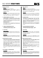
3. GONG
Taster zur Gongauslösung und Lautstärkeregler.
4. TELEPHONE
TEL NIGHT RINGER:
Tastschalter für "Tel night ringer" und Lautstärkeregler.
Bei eingeschalteter "Tel night ringer" Funktion und An-
legen eines Klingelsignals (8 - 12V Wechselspannung)
kann eine Glocke über Lautsprecher gehört werden.
Wenn der Lautstärkeregler auf "LEAK" steht, wird eine
Dämpfung von -20 dB erreicht.
PAGING:
Lautstärkeregler für "Paging-Eingang“. Wenn der Laut-
stärkeregler auf "LEAK" steht, wird eine Dämpfung von
-20 dB erreicht.
5. SIRENE
Tastschalter für auf- und abschwellende Sirene. Tast-
schalter für Dauerton und Lautstärkeregler.
6. MASTER
"MASTER" Lautstärkeregler. Alle Signale ob Module, Si-
rene, Mikrophone usw. können nur über den jeweiligen
Lautstärkeregler und den "MASTER" Regler eingestellt
werden.
7. SPEAKER ZONES & ATT.
Lautsprecher Ausgänge:
Die Lautstärke der 6 Lautsprecherkreise kann in 6 Schrit-
ten (100V-70V-50V-25V-12,5V-8,9V) geregelt werden.
Jeder Kreis kann separat geregelt und über einen Tast-
schalter aktiviert werden.
Bei Signalen die durch Priorität der Mikrofonsprechstel-
len empfangen werden, werden diese Regler deaktiviert
und es erfolgt max. Lautstärke über "ALL CALL".
WICHTIG: Die Gesamtleistung von 120/240/360/480
bzw. 600 W darf nicht überschritten werden. Die Gesamt-
leistung kann auch über einen der Kreise 1-6 abgegriffen
werden.
Output Level LED‘s:
Die "0" der LED Anzeige sollte nicht überschritten wer-
den, wenn die rote "CLIP" Diode leuchtet ergibt sich eine
Verzerrung des Eingangssignales.
8. POWER
Power Ein/Aus Schalter. Leuchtdioden für "STAND BY"
und "POWER".
9. EQ-Regler
Regler für Tiefen sowie Höheneinstellung eines Einbau-
moduls, z.B. CDR-10 RDS, DM-10, etc.
10. MODUL-EINSCHUBSCHACHT
Leerfeld zur Installation eines der RCS Tonträgermodule
CR-10, TP-10, CP-10, DM-10, CDP-10 M oder CDR-10
RDS.
3. CHIME
Button to activate chime and volume controller.
4. TELEPHONE
TEL NIGHT RINGER:
TEL night ringer function let you hear telephon ring Via
speaker. Turn RINGER volume to clock-otherwise for ring
decrease, even RINGER volume go to clock-otherwise
completely, you can hear night Tel ring by dark function
(-20db attenuation from max volume).
PAGING:
You can adjust broadcasting level when broadcasting by
telephone paging is operated, even PAGING volume go to
clock-otherwise completely, you can hear night TEL ring
by dark funktion (-20db attenuation from max volume).
5. SIREN
This is for emergency situation: Alert siren curve (repeat)
or Alert siren at (continuously).
6. MASTER
All signals from modules and others, are adjusted by MA-
STER volume to supply power amplier placement ma-
ster volume in the circuit is located between rear of "amp
in" connector and front side power amplier.
7. SPEAKER ZONES & ATT.
Loud speaker output:
The loud speaker for up to six speaker zones can be atte-
nuated by six steps (100V-70V-50V-25V-12,5V-8,9V) per
zone. The stepping switches are utilized to control the
output level of each zone separately.
Whenever prioritized messages, alert, all calls by manual
or priority switch of P.T.T microphone are activated, the-
se controls are automatically deactivated and the signal
is reproduced at its maximum volume level.
IMPORTANT NOTE: The total output of 120/240/360/480
or 600 W may not be exceeded. The total output can be
measured also over one of the circles 1-6.
Output Level LED‘s:
Normal operating of amplier is "0" on the LED indicator,
if clip LED ash like a lamp, decrease output volume.
8. POWER SUPPLY
Push power switch. Then, power Led will be "ON"
whenever AC main supply is interrupted, secondary po-
wer source (battery) is performed automatically.
9. EQ CONTROLLER
Controller for depths as well as height adjustmenting an
installation module, e.g. CDR-10 RDS, DM-10, …
10. MODUL INSERTION COMPARTMENT
Slot to install one of the RCS Sound-Source-Modules
CR-10, TP-10, CP-10, DM-10, CDP-10 M or CDR-10
RDS.
VLZ-SERIES FRONT PANEL

8
ONONON
AC POWER
DC FUSE
FUSE INSIDE
Fuse Rating
T40AL 32V
REMOTE
DC POWER
24V 40A
AC 230V /50Hz
1420W
LOW
IMP
HIGH
IMP
4
3
2
1
56
NIGHT
RINGER
PAGING
IN
TEL
MESSAGE
FIRST
PRIORITY
ATT. OUTPUTS
SPK ZONES
4 100V
FD-21
Fault Detector
FM-30
ANT
Fault DC/AC/FAN
Monitor
EACH ZONE / (MAX)
Remote
Receiver
Remote
Receiver
Feedback
Reduction
Feedback
Reduction
RR-600RR-600
FS-40FS-40
IN
8Hz 9Hz 10Hz
NOR
OUT
OPERATE
7Hz 7Hz 7Hz
40
PRIORITY
1
2
3
N
O
VLM-200
DC 24V
OUTPUT
MIC
PRIORITY
VLM-100A
1357
2468
24V
AUDIO
PRIORITY
CHIME
1357
2468
24V
AUDIO
PRIORITY
CHIME
VLM-100AVLM-200A
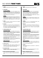
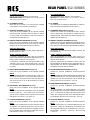
RÜCKANSICHT VLZ-SERIE
1. MIC PRIORITY Schalter
3-fach Schalter um die Priorität der Mikrophoneingänge
1 bis 3 zu aktivieren. MIC 1 - 3 können separat auf "on"
(Priorität) gestellt werden. Dadurch wird Priorität gegen-
über den LINE Eingängen 4, 5, Night Ringer, Sirene und
allen Modulen (außer DMT-10) erreicht, vorrausgesetzt
der Jumper MS 2 steht auf "SLAVE".
2. P.T.T REMOTE
RJ45-Buchse für P.T.T Mikrophon (VLM-100A) und 24V
Ausgang. Damit können 24V Pichtrufrelais geschal-
tet werden. Die 24V liegen an, wenn die Priorität der Mi-
krophon-Sprechstelle VLM-100 aktiviert ist und betätigt
wird.
Für Mikrophonsprechstelle-VLM-100 "Phantom Power"
einschalten und Gain-Regler Eingang 1 auf MIC-Position
drehen.
3. MIC / LINE INPUTS
Drei symmetrische MIC/LINE-Eingänge auf Combo-Buch-
sen (XLR und Klinke). Je 1 Gain Regler von -10dB (LINE) bis
-50 dB (MIC).
Tastschalter für "Phantom Power" (Kondensatormikro-
phon). Für jeden MIC / LINE Eingang ist ein separater
Tastschalter für "Phantom Power" vorhanden.
4. LINE-IN 4 & 5
Die Eingänge 4 und 5 (L + R, unsymmetrische Cinch-
buchsen) sind zum Einschleifen von CD-Player, Kasset-
ten-Deck, o.ä. vorgesehen.
5. REC OUTPUT
Recording output auf Cinchbuchsen, unsymmetrisch,
0dB. Hiermit können alle eingespeisten Signale aufge-
zeichnet werden. Die Lautstärkeregelung erfolgt dabei
über den Regler welcher dem eingespeisten Signal zuge-
ordnet ist, nicht über den "MASTER" Regler.
REAR VIEW VLZ-SERIES
1. MIC PRIORITY SWITCH
Triple switches to activate the priority of the microphone
input 1 to 3. MIC 1 - 3 can be switched separately to “on”
(priority). Because of that and if the Jumper MS 2 is swit-
ched to “SLAVE”, priority is reached opposite of the LINE
inputs 4 and 5, Night Ringer, Siren and all modules (ex-
cept DMT-10).
2. P.T.T REMOTE JACK (DIN 7 PIN)
The RJ45 connector connecting P.T.T Remote
(VLM-100A) and 24V Output, to switched the 24V
obligation call relays. The 24V connected, if the priority
of the microphone station VLM-100 is activated and one
operates.
Switch to "Phantom Power" for microphone station
VLM-100. Turn the Gain control input 1 to MIC position.
3. MIC / LINE INPUT
Three MIC/LINE-Inuts with gain control on balanced
combo sockets (XLR and jack). Variable range of input
gain is -10dB to -50dB.
Push-button for "Phantom Power" (condenser micropho-
ne). For each MIC/LINE input is a separate push-button
for “phantom power” available.
4. LINE-IN 4 & 5
The input 4 and 5 (L + R, unbalanced jack plugs) are used
for the connection of line-level equipment such as tape
decks, CD-players, or similar.
5. REC OUTPUT
Recording output designed with two unbalanced (0dB)
jack plugs. All signals can be recorded but recording
out can not be adjusted by master volume because re-
cording output is in the front of circuit of master volume
control.
G J
CD
H I Q O M
N
P
A
R
B
S
EFKL
REAR PANEL VLZ-SERIES

9
6. AMP IN / PRE OUT
AMP IN:
Jack socket (6.3 mm), unbalanced.
IMPORTANT NOTE: If a jack is plugged on "AMP IN",
all other signals are closed. To adjust it operate the
"MASTER" control.
PRE OUT:
Jack (6.3 mm) which supplying signal to other products,
has been designed for 1/4" unbalanced phone jack. It
can be only occupied either “AMP IN” or “PRE OUT”.
7. SPEAKER ZONES & ATT. OUTPUT
Pushing speaker zone selector (front panel NO.7), signal
will be assigned to the selected zone. If all call switch,
P.T.T microphone priority and zone selector of remote
controller are activated, selected zone output outputare
reseted to 100V/70V output.
IMPORTANT NOTE:
The total output of 120/240/360/480 or 600 W may not
be exceeded. The total output can be measured also
over one of the circles 1-6.
8. LOW/HIGH IMPEDANCE OUTPUT
LOW IMP (low-resistant output)= 4 ohms,
HIGH IMP (high-resistant output)= 100 V
9. TELEPHONE
NIGHT RINGER:
Input for the signal of a telephone bell or night bell; the in-
put signal releases a ringing tone which can be heard via
the PA system.
PAGING IN:
Input (bal., 250 mV) to connect the telephone exchanger for
a telephone signal which is to be heard via the PA system.
10. MESSAGE FIRST PRIORITY
This is a switch terminal which make rst ranking priority
memoried on memory bank No. 6 against other memo-
ry bank on the digital message how to set rst priority
racking. First, be sure to place "o" of MS802 PCB/RR-
60 after recording on the M6 of DMT-10. Second, move
Jumper MS2 to the "PRIORITY".
IMPORTANT NOTE: When placing "off" MS802 of RR-
60, it is impossible to play, repeat, warnning of memory
bank M6 by VLM-206. When factory production for the
above, MS 2 is "SLAVE", MS802 of remote receiver PCB
is "off"
11. DC POWER, AC POWER REMOTE
DC POWER:
This terminal is emergency power battery connection.
The battery connection cord has to be 5,0 mm in diame-
ter and this diameter should not be any longer than 4 me-
ters. Fuse is located in the PCB FU 3.
6. AMP / PRE OUT
AMP IN:
Klinkenbuchse, 6,3 mm, unsymmetrisch.
WICHTIG: Ist ein Klinkenstecker am "AMP IN" Eingang
gesteckt sind alle anderen Signale gesperrt. Die Rege-
lung erfolgt über den "MASTER" Regler.
PRE OUT:
Klinkenbuchse, 6,3 mm, unsymmetrisch, zum Kaskadie-
ren mit weiteren Verstärkern und Signalausgang. Es kann
nur entweder "AMP IN" oder "PRE OUT" belegt werden.
7. SPEAKER ZONES
Ausgänge der 5 Lautsprecherkreise, einzeln einschaltbar
und zu regeln in 6 Schritten (100V - 70V - 50V - 25V -
12,5V - 8,9V) oder über "ALL CALL" (100V). Wenn die Pri-
orität der P.T.T Mikrophonsprechstelle aktiviert ist werden
alle Kreise auf "ALL CALL" geschaltet.
WICHTIG: Die Gesamtleistung von 120/240/360/480
bzw. 600 W darf nicht überschritten werden. Die Gesamt-
leistung kann auch über einen der Kreise 1-6 abgegriffen
werden.
8. LOW/HIGH IMPEDANCE AUSGANG
LOW IMP (Niederohmiger Ausgang) = 4 Ohm
HIGH IMP (Hochohmiger Ausgang) = 100 V
9. TELEPHONE
NIGHT RINGER:
Eingang für das Signal einer Telefon- oder Nachtklingel;
das Eingangssignal löst ein Rufzeichen aus, das über die
ELA-Anlage zu hören ist.
PAGING IN:
Eingang (sym., 250 mV) für ein Telefonsignal von der
Telefonzentrale, das über die ELA-Anlage zu hören sein soll.
10. MESSAGE FIRST PRIORITY
Fernsteuerung der vollen Leistung ("ALL CALL"), z.B. für
Feueralarmdurchsage oder als Anschlußklemme zum
Aktivieren des Speichers 6 des DMT-10.
Dazu muß der Schalter MS802 auf der digitalen Schnitt-
stelle RR-60 auf "o" gestellt werden und der Jumper
MS2 auf "Priority".
Wichtig: Wenn der Schalter MS802 auf "off" steht, ist es
nicht möglich die Message Bank Nr. 6 über die digitale
Mikrophon-Sprechstelle VLM-206 zu aktivieren.
Die Einstellung ab Werk ist folgende: MS 2 "SLAVE"
MS802 "OFF"
11. DC POWER, AC POWER REMOTE
DC POWER:
Anschlußklemme für Notstromversorgung-Gleichstrom
24V. Die Verbindungsleitung sollte einen Querschnitt von
5,0 mm haben und nicht länger als 4 m sein. Die Siche-
rung bendet sich auf PCB FU 3.
VLZ-SERIES REAR PANEL

10
REAR PANEL VLZ-SERIES
AC POWER REMOTE:
You can turn on/o amplier by remote control.
IMPORTANT NOTE: The amplifier must not be switched
„ON“ via the power switch!
12. AC POWER SOCKET
Mains jack for connection to a socket via the supplied
mains calbe. Fuse is located in the PCB FU 1.
13. ANTENNA TERMINAL (optional)
Empty slot for the installation of the optional available
antenna terminal, is packed with tuner pack TP-10RDS
or CDR-10USB. Or installation of the control output of
the digital text module DMT-10.
14. REMOTE CONTROL RECEIVER (optional)
Empty slot for the installation of the optional available
Remote control receiver RR-60 (in the scope of supply of
the VLM-106 and VLM-206 microphone stations).
DATA LED INDICATOR:
In case of normal operation of data receipt, data LED in-
dicator will be turn "ON".
SLAVE / PRIORITY SWITCH:
If "SLAVE" is switched, all signal output of microphone
station VLM-106/206 will be closed under setting "on" of
priority switch on the rear of P.T.T remote.
If "PRIORITY" is switched the micorphone station VLM-
106/206 is prior to any other signals priority. Only the
P.T.T microphone station can be activated, with switched
on priority.
15. ERROR MONITORING-MODULE (optional)
Empty slot for the installation of the optional available
FM-30:
Three potential-free Relay contacts (NO/NC). Fault moni-
toring is operating if AC- or DC-fuse is blown and if AC-
or DC- power is o or disconnected. Also the module re-
acts when fan fault or fan is disconnected (more details
see on page 14).
16. FREQUENCY SHIFT-MODULE (optional)
Empty slot for the installation of the optional available
FS-40:
Module for the reduction of feedback noise. The possible
frequency shifts of 7 - 10 Hz make sense, even if back-
ground music in addition to microphone announcements
take place (more details see on page 15).
17. PILOTTONE-MODULE (optional)
Empty slot for the installation of the optional available
FD-21:
This pilot tone module serves to monitor the performance
of ampliers. The generator produces a 20 kHz test si-
gnal. Apart from the test of the power amplier function-
ing, the speaker line is checked for breaks and short cir-
cuit faults (more details see on page 11).
AC POWER REMOTE:
Zur Fernbedienung für "ON/OFF" des Verstärkers.
WICHTIG: Der Hauptschalter des Verstärkers "Power"
darf nicht auf "ON" stehen!
12. AC POWER
Anschlußstecker für Kaltgeräte-Netzkabel (im Lieferum-
fang). Die Sicherung bendet sich auf PCB FU 1.
13. ANTENNEN ANSCHLUSS (optional)
Leerfeld zum Einbau des Antennenterminals, welches
sich im Lieferumfang der Module TP-10RDS und CDR-
10USB bendet. Oder Einbau des Steuerausgangs vom
digitalen Textmodul DM-10.
14. REMOTE CONTROL RECEIVER (optional)
Leerfeld zum Einbau der digitalen Schnittstelle RR-60 zur
Steuerung der digitalen Mikrophonsprechstellen VLM-
106 / 206 (im Lieferumfang der Sprechstellen enthalten).
DATA LED ANZEIGE:
Bei Betrieb der Mikrophonsprechstellen leuchtet die
Leuchtdiode auf.
SLAVE / PRIORITY SCHALTER:
Wenn der Tastschalter auf "SLAVE" steht und die P.T.T.
Sprechstellenpriorität auf "on", hat diese Vorrang gegen-
über der VLM-106/206.
Wenn der Tastschalter auf "PRIORITY" steht, haben die
Sprechstellen VLM-106/206 Vorrang gegenüber allen an-
deren Signalen. Nur die P.T.T Sprechstelle kann, bei ein-
geschalteter Priorität, aktiviert werden.
15. FEHLER MONITORING MODUL (optional)
Leerfeld für optional erhältliches Erweiterungsmodul
FM-30:
Mit 3 potentialfreien Relaiskontakten (NO/NC).Fehlermel-
dung bei Ausfall der AC- oder DC-Stromversorgung, bei
defekten AC oder DC Sicherungen und bei Ausfall des
Lüfters (detailierte Beschreibung s. Seite 14).
16. FREQUENZSHIFTER MODUL (optional)
Leerfeld für optional erhältliches Erweiterungsmodul
FS-40:
Zur Unterdrückung von Rückkopplungen. Die hiermit
möglichen beinahe unhörbaren Frequenzverschiebungen
von 7 - 10 Hz können vor allem dann sinnvoll sein, wenn
neben der Hintergrundmusik auch Mikrophondurchsa-
gen stattnden (detailierte Beschreibung s. Seite 15).
17. PILOTTON-MODUL (optional)
Leerfeld für optional erhältliches Erweiterungsmodul
FD-21:
20 kHz Pilottonmodul zur Funktionsüberwachung des
Verstärkers. Neben der Überprüfung der Endstufe wird
die Lautsprecherleitung auf Unterbrechungs- und Kurz-
schlussfehler gemessen (detailierte Beschreibung
s. Seite 12).

11
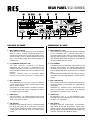
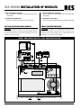
VLZ-SERIES INSTALLATION OF MODULES
CN5
SW1
OFF ON
CN601
CN801
AS802 AS903
MS802
OFF ON
AS204
AS4-1
Connection module
(RR60) for VLM-Series
DM-10
CN 903
AN 802
CN 901
DM-10
FS-40
CN801
AN801
CN702
MS 2 MS 1
2T4T
PRI TO PACKSLAVE
FM-30FD-21
MS 802
ONOFF
MS 401
FRBY
SW 1
ONOFF
AN 702
A
B
C
EINBAU VON ZUSATZMODULEN
WARNUNG: Der Einbau von Zusatzmodulen darf nur durch
Fachpersonal erfolgen. Vor dem Öffnen des Verstärkers den
Netzstecker aus der Steckdose ziehen, anderenfalls besteht
die Gefahr eines elektrischen Schlages!
INSTALLATION OF ADDITIONAL MODULES
WARNING: Additional modules must only be installed by
specialized personnel. Prior to opening the amplifier discon-
nect the mains plug from the socket, otherwise there is the
hazard of an electric shock!
LAYOUT- AND CONNECTION PLAN / LAGE- UND ANSCHLUSSPLAN
18. DC 24V PRIORITÄT AUSGANG
DC 24V Ausgang für Pichtrufrelais (für VLM-100A oder
VLM-200A).
19. ANSCHLUSS VLM-200A
RJ-45 Anschluss für Mikrophon-Sprechstelle VLM-200A
18. DC 24V PRIORITY OUTPUT
DC 24V output for mandatory call relay (für VLM-100A or
VLM-200A).
19. VLM-200A CONNECTION
RJ-45 connection for microphone unit VLM-200A

12
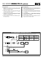
PILOTTONE-MODULE FD-21
The fault detecting module is available as
an accessory and is not supplied with the
amplier.
It is inserted instead of the cover plate
(see rear view no.
Q).
1. Relay output for connection of a signal device
2. Connections COM and HOT;
to be connected to the connections HIGH IMP (see rear
view no.
8): COM at B, HOT at A
3. Measuring points for adjusting the response sensitivity.
2. Control for the 20 kHz test tone level.
5. Control for the response sensitivity.
FD-21 INSTALLATION STEPS:
1. Disconnect the amplier from the mains and from the
emergency power supply.
2. Screw o the housing cover of the amplier and remove
the cover plate
Q.
3. Insert the module PA-6FD from the outside at the place
of the cover plate and screw it tightly.
4. Connect the 5-pole line (B) of the amplier to the jack
CN 601 of the module (see layout plan page 11).
5. Connect the negative contact of the connection HIGH
IMP at the amplier to the contact COM of the screw ter-
minal Line In
b at the module and the positive contact
of HIGH IMP to the contact HOT of Line In.
6. Connect the jumper SW 1 on the monitoring module to
position ON.
7. If a fault is recognized by the module, the LED FAULT
lights up and the relay contacts
a close. For alarm trig-
gering, a signal device may be connected to the con-
tacts. The rating of the relay contacts is 1 A at 120 V~
max. or 24 V max.
Fault Detector
COM HOT
Line In
Test
RMS 2Vac
Sensitivity
maxmin
OSC Level
FD-21
a b c ed
Fault Detector
COM HOT
Line In
Test
RMS 2Vac
Sensitivity
maxmin
OSC Level
FD-21
AC POWER
DC FUSE
FUSE INSIDE
Fuse Rating
T40AL 32V
REMOTE
DC POWER
24V40A
AC 230V /50Hz
1420W
LOW
IMP
HIGH
IMP
4
3
2
1
56
NIGHT
RINGER
PAGING
IN
TEL
MESSAGE
FIRST
PRIORITY
ATT. OUTPUTS
SPK ZONES
4 100V
EACH ZONE / 80W(MAX)
40
LAUD SPEAKERS
PILOTTON-MODUL FD-21
Das Fehlerüberwachungsmodul ist als
Zubehör erhältlich und gehört nicht zum
Lieferumfang des Verstärkers.
Es wird anstelle des Abdeckbleches
(s. Rückansicht Nr.
Q) eingesetzt.
1. Relaisausgang zum Anschluss eines Signalgebers.
2. Anschlüsse COM und HOT;
mit den Anschlüssen HIGH IMP (s. Rückansicht Nr.
8)
verbinden: COM an
B, HOT an A.
3. Messpunkte zum Einstellen der Ansprechempndlichkeit.
4. Regler für den 20-kHz-Testtonpegel.
5. Regler für die Ansprechempfindlichkeit.
FD-21 INSTALLATIONS SCHRITTE:
1. Den Verstärker vom Netz und von der Notstromversor-
gung trennen.
2. Den Gehäusedeckel des Verstärkers abschrauben und
das Abdeckblech
Q am Verstärker entfernen.
3. Das Modul FD-21 an der Stelle des Abdeckblechs von
außen einsetzen und festschrauben.
4. Die 5-polige Leitung (B) des Verstärkers in die Buchse
CN 601 des Moduls stecken (s. Anschlußplan Seite 11).
5. Den Minuskontakt des Anschlusses HIGH IMP am Verstär-
ker mit dem Kontakt COM der Schraubklemme LINE IN
b am Modul verbinden und den Pluskontakt von HIGH
IMP mit dem Kontakt HOT von LINE IN.
6. Die Steckbrücke SW 1 auf dem Überwachungsmodul in
die Position ON stecken.
7. Wird von dem Modul ein Fehler erkannt, leuchtet die An-
zeige FAULT am Verstärker und die Relaiskontakte
a
schließen. An die Kontakte lässt sich zur Alarmierung ein
Signalgeber anschließen. Die Belastbarkeit der Relais-
kontakte beträgt 1 A bei max. 120 V~ oder max. 24 V .
(optional) MODULE FD-21 VLZ-SERIES

13
VLZ-SERIES MODULE FD-21 (optional)
FD-21 Kalibrierung
1. Den Verstärker einschalten und den Lautstärkeregler MA-
STER auf Null drehen, damit nur der 20-kHz-Testton an
den Lautsprecherausgängen anliegt.
2. Am Anschluss HIGH IMP die Spannung des 20-kHz-Test-
tons messen und mit dem Trimmregler OSC Level
d auf
2 V~ einstellen.
3. An den Messpunkten „+ -“
c des Moduls die Spannung
des 20-kHz-Testtons kontrollieren. Mit dem Trimmregler
Sensitivity
e 2 V~ einstellen.
4. Nach der Kalibrierung den Regler MASTER wieder auf
die gewünschte Lautstärke drehen.
FD-21 Calibration
1. Switch on the amplier and turn the volume control
MASTER to zero so that only the 20 kHz test tone is
present at the speaker outputs.
2. Measure the voltage of the 20 kHz test tone at the
connection HIGH IMP and adjust it to 2 V~ with the
trimming control OSC Level
d.
3. Check the voltage of the 20 kHz test tone at the measu-
ring points “+ -”
c of the module. Adjust 2 V~ with the
trimming control Sensitivity
e.
4. After the calibration turn the control MASTER again to
the desired volume.
Line in (COM, HOT)
AMP Condition
AMP NORMAL LINE NORMAL
AMP FAULT
Relay Contact
Condition
Speaker Line
Condition
LINE OPEN or
LINE SHORT
20KHz Signal
(N.O)
20KHz No Signal
(N.C)
MUTE
IN
CN601
CN602
GND
20KHz
+24V
COM
HOT
TEST
RMS 2Vac
LINE IN
FD-21
ON OFF
OSC OUT
LEVEL
20KHz
Generator
SENSITIVITY
LEVEL
+24V
+24V
COM
N.C
B.A
20KHz
Detector
20KHz
Filter
Operating Condition of FD-21 / Betriebsbedingungen des FD-21
FD-21 BLOCK DIAGRAM / BLOCKSCHALTBILD DES FD-21

14
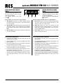
(optional) MODULE FM-30 VLZ-SERIES
FEHLER MONITORING-MODUL
FM-30
Das Fehlermeldemodul ist als Zubehör
erhältlich und gehört nicht zum Liefer-
umfang des Verstärkers.
Es wird anstelle des Abdeckbleches
O eingesetzt.
Relaisausgänge zum Anschluss von Signalgebern:
1. Relais AC spricht an, wenn keine Netzspannung anliegt,
die interne Netzsicherung durchgeschmolzen ist oder
der Netzschalter nicht auf ON steht.
2. Relais DC spricht an, wenn die Sicherung für die
Notstromversorgung durchgeschmolzen ist oder keine
Spannung von einer Notstromeinheit an den Anschlüs-
sen DC POWER anliegt.
3. Relais FAN spricht an, wenn der interne Lüfter defekt
oder nicht angeschlossen ist.
FM-30 INSTALLATIONS SCHRITTE:
1. Den Verstärker vom Netz und von der Notstromversor-
gung trennen.
2. Den Gehäusedeckel des Verstärkers abschrauben und
das Abdeckblech entfernen.
3. Das Modul FM-30 an der Stelle des Abdeckblechs von
außen einsetzen und festschrauben.
4. Die 6-polige Leitung (C) des Verstärkers in die Buchse
CN 5 des Moduls stecken (s. Anschlußplan Seite 11).
5. Die Signalgeber zur Alarmierung an die Relaisumschalt-
kontakte
a, b oder c anschließen.
Der Aufdruck am Modul zeigt die Kontaktstellung im Feh-
lerfall und bei ausgeschaltetem Verstärker. Die Belastbar-
keit der Relaiskontakte beträgt 1 A bei max. 120 V~ oder
max. 24 V .
ERROR MONITORING MODULE
FM-30
The fault monitoring module is availa-
ble as an accessory and is not sup-
plied with the amplier.
It is inserted instead of the cover
plate
O.
Relay outputs for connection of signal devices:
1. The relay AC responds if no mains voltage is present,
the internal mains fuse is blown, or the mains switch is
not in ON position.
2. The relay DC responds if the fuse for the emergency po-
wer supply is blown or if no voltage from an emergency
power supply unit is present at the connections DC PO-
WER.
3. The relay FAN responds if the internal fan is defective or
if it is not connected.
FM-30 INSTALLATION STEPS:
1. Disconnect the amplier from the mains and from the
emergency power supply.
2. Screw o the housing cover of the amplier and remove
the cover plate.
3. Insert the module FM-30 from the outside at the place of
the cover plate and screw it tightly.
4. Connect the 6-pole line (C) of the amplier to the jack
CN 5 of the module (see layout plan page 11).
5. Connect the signal devices for alarm triggering to the re-
lay switching contacts
a, b or c .
The imprint on the module shows the contact position in
cause of fault and with the amplier switched o. The ra-
ting of the relay contacts is 1 A at 120 V~ max. or 24 V
max.
AC DC FAN
FM-30 Fault Monitor AC/DC/FAN Module
a b c

15
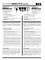
VLZ-SERIES MODULE FS-40 (optional)
FREQUENZSHIFTER-
MODUL FS-40
Das Antirückkopplung-Modul
ist als Zubehör erhältlich und
gehört nicht zum Lieferumfang
des Verstärkers.
Es wird anstelle der Abdeck-
blende
P eingesetzt.
1. Umschalter ACTIVE
IN = Frequenzverschiebung aktiviert
OUT = keine Frequenzverschiebung
2. DIP-Schalter
zur Auswahl der Frequenzverschiebung (2, 4, 5 oder 6 Hz)
3. Betriebsanzeige:
blinkt, wenn der Verstärker eingeschaltet
Das als Zubehör lieferbare Antirückkopplungs-Modul FS-40
ist speziell für diesen Verstärker konzipiert. Das Signal des
Eingangs 1 wird über das Modul geleitet und in der Frequenz
erhöht (2, 4, 5 oder 6 Hz, einstellbar). Durch die Frequenz-
verschiebung wird ein optimaler Schutz gegen akustische
Rückkopplungen erreicht.
FS-40 INSTALLATIONS SCHRITTE:
1. Den Verstärker vom Netz und von der Notstromversor-
gung trennen.
2. Den Gehäusedeckel des Verstärkers und die Blende auf
der Verstärkerrückseite abschrauben.
3. Das Modul in die durch die Blende freigegebene Ausspa-
rungen einsetzen und festschrauben.
4. Die 2-polige Leitung AN 702 (schwarz-braun) des Ver-
stärkers in die Buchse CN 702 des Moduls stecken (s.
Anschlußplan Seite 11).
5. Die schwarz-rote 2-polige Leitung (A) des Verstärkers in
die Buchse CN 801 stecken. Wenn das Anschlussmo-
dul für das Kommandomikrofon VLM-106/206 zuvor ein-
gesetzt wurde, steckt die 2-polige Leitung bereits in der
Buchse CN801 des Anschlussmoduls (gestrichelte Linie
im Anschlußplan Seite 11). Die Leitung vom Anschluss-
modul abziehen und in die Buchse CN801 des FS-40
stecken. Dafür die 2-polige Leitung AN 801 des FS-40 in
die Buchse CN801 des Anschlussmoduls stecken.
6. Die Brücke MS 401 des Verstärkers in die Position „FR“
setzen.
FS-40 BEDIENUNG
Nach der Inbetriebnahme des Verstärkers den Schalter
ACTIVE
a in die Position IN stellen. Über den Eingang 1
eine Ansage in erforderlicher Lautstärke durchgeben. In der
Grundeinstellung, wenn alle DIP-Schalter
b in der oberen
Position stehen, beträgt die Frequenzverschiebung 2 Hz.
Sollte es trotz dieser Frequenzverschiebung zu einer Rück-
kopplung kommen, mit den DIP-Schaltern eine höhere Fre-
quenzverschiebung einstellen.
FREQUENCY SHIFT-
MODULE FS-40
The anti-feedback module is
available as an accessory and is
not supplied with the amplier.
It is inserted instead of the
cover plate
P.
1. Selector switch ACTIVE
IN = frequency displacement activated
OUT = no frequency displacement
2. DIP switches
for selection of the frequency displacement (2, 4, 5 or 6 Hz)
3. Power LED:
ashes if the amplier is switched on
The anti-feedback module FS-40 available as an accessory
is especially designed for this amplier. The signal of input 1
is routed via the module and increased in frequency (2, 4,
5, or 6Hz can be adjusted). Due to the frequency displace-
ment, an optimum protection against acoustic feedback is
reached.
FS-40 INSTALLATION STEPS:
1. Disconnect the amplier from the mains and from the
emergency power supply.
2. Screw o the housing cover of the amplier and the
cover on the rear side of the amplier.
3. Insert the module into the cutouts which are uncovered
when removing the cover and screw it tightly.
4. Connect the 2-pole line AN 702 (black-brown) of the am-
plier to the jack CN 702 of the module (see layout plan
page 11).
5. Connect the black-red 2-pole line (A) of the amplier to
the jack CN 801. If the connection module for the zone
paging microphone VLM-106/206 has been inserted be-
fore, the 2-pole line is already connected to the jack CN
801 of the connection module (dashed line in the see lay-
out plan page 11). Disconnect the line from the connec-
tion module and connect it to the jack CN 801 of the FS-
40. For this purpose connect the 2-pole line AN 801 of
the FS-40 to the jack CN 801 of the connection module.
6. Place the jumper MS 401 of the amplier to position
“FR”.
FS-40 OPERATION
After setting the amplier into operation, set the switch AC-
TIVE
a to position IN. Via the input 1 make an announce-
ment in the required volume. In the basic setting, when all
DIP switches
b are in the upper position, the frequency
displacement is 2 Hz. If an acoustic feedback should occur
in spite of this frequency displacement, adjust a higher fre-
quency displacement with the DIP switches.
NOR
ACTIVE
OUT IN
ON
12
4Hz
2Hz
ON
12
5Hz
2Hz
ON
12
6Hz
2Hz
FS-40
Feedback
Reduction
a b c

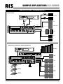
16
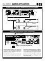
SAMPLE APPLICATIONS / ANWENDUNGSBEISPIELE
RESTAURANT
LINE
4 INPUT
MIC
3 INPUT
MIC
ON/OFF
S/W
ZONE 1
ZONE 2
ZONE 3
ZONE 4
ZONE 5
ZONE 6
GARDEN
COUNTER & BAR
LOBBY
RESTAURANT
TOILET
etc...
CD PLAYER
<<
<<
CD-POWER
PLAY/
PAUSE
MAIN POWER
<<
<
<
TRACK
DISC
SENSOR
POWER
0 10
STOP
REPEAT RANDOM
SCAN
EJECT
LEVEL
R6CD-10
6CD CHANGER
PROTECT FAULT
SPEAKER ZONES & A.T.T
VLZ-6480
6 ZONE MIXING AMPIFIER
INDUSTRIAL ENTERPRISE AND SUPERMARKET
STOCK
HOUSE
LOBBY
ADMINIS
-
TRATION
OFFICE
1
2
3
1
6
2
5
3
4
P
O
W
E
R
R
E
P
E
A
T
/
S
T
O
P
S
T
A
R
T
/
S
T
O
P
DIGI
T
AL
MA
S
S
A
G
E
ME
S
S
AG
E
B
A
N
K
TA
L
K
S
E
N
D
B
US
Y
1
AL
L
C
AL
L
S
P
EA
KE
RZ
O
N
E
SS
E
LE
CT
OR
2
3
4
5
Remote Controller RC-600
VLM-106/206
24VDC
BATTERY
MANUFACTURING
-AREA OR SHOP
CD PLAYER
LINE
4 INPUT
LINE
5 INPUT
ZONE 1
ZONE 2
ZONE 3
ZONE 4
ZONE 5
ZONE 6
INFO DESK
VLM-106/206
SECRETARY
VLM-106/206
SUPER INTENDENT
1
6
2
5
3
4
P
O
WE
R
R
E
PE
A
T
/
S
T
O
P
S
T
AR
T
/
S
T
O
P
D
I
G
I
T
AL
M
A
SS
AGE
M
E
S
S
AGE
BA
NK
T
A
L
K
SE
N
D
B
U
S
Y
1
A
L
L
C
AL
L
S
P
EA
K
ER
Z
O
N
E
SSE
LE
CT
O
R
2
3
4
5
Remote Controller RC-600
1
6
2
5
3
4
P
O
WE
R
R
E
PE
A
T
/
S
T
O
P
S
T
AR
T
/
S
T
O
P
DI
GI
T
AL
M
A
S
S
AGE
ME
S
S
A
G
E
BAN
K
T
A
L
K
SE
N
D
B
U
SY
1
A
L
L
CA
LL
S
P
E
A
K
E
RZ
ON
E
SS
E
L
E
C
T
O
R
2
3
4
5
Remote Controller RC-600
etc....
M1 M2 M3 BAND
TUNE
SCAN UP
M4 M5 M6
A PS MUTE
SEEK UP
STER
MONO
TU-110B
AM/FM TUNER
STATION
CALL
STEREO
MODE
FUNCTION
POWER
SIGNAL STRENGTH
TUNE
0 10
LEVEL
R6CD-10
6CD CHANGER
<<
<<
CD-POWER
PLAY/
PAUSE
MAIN POWER
<<
<<
TRACK
DISC
SENSOR
POWER
0 10
STOP
REPEAT RANDOM
SCAN
EJECT
LEVEL
PROTECT FAULT
SPEAKER ZONES & A.T.T
VLZ-6480
6 ZONE MIXING AMPIFIER
SAMPLE APPLICATIONS VLZ-SERIES

17
CASCADING WITH OTHER AMPLIFIERS / KASKADIERUNG MIT WEITEREN VERSTÄRKERN
24VDC
CONNECT THIS TO TERMINAL OF FIRE RECEIVER CLOSED
RELAY FOR EMERGENCY.
USE DIODE 1N 4007 BETWEEN POWER REMOTE AND
FIRST PRIORITY MESSAGE.
BATTERY
AUTOMATIC POWER SUPPLY AND AUTOMATIC ALERT VOLCE MESSAGE.
ONONON
AC POWER
DC FUSE
FUSE INSIDE
Fuse Rating
T40AL 32V
REMOTE
DC POWER
24V 40A
AC 230V /50Hz
1420W
LOW
IMP
HIGH
IMP
4
3
2
1
56
NIGHT
RINGER
PAGING
IN
TEL
MESSAGE
FIRST
PRIORITY
ATT. OUTPUTS
SPK ZONES
4 100V
FD-21
Fault Detector
FM-30
ANT
Fault DC/AC/FAN
Monitor
EACH ZONE / (MAX)
Remote
Receiver
Feedback
Reduction
RR-600
FS-40FS-40
IN
8Hz 9Hz 10Hz
NOR
OUT
OPERATE
7Hz 7Hz 7Hz
40
PRIORITY
1
2
3
NO
VLM-200
DC 24V
OUTPUT
MIC
PRIORITY
VLM-100A
1357
2468
24V
AUDIO
PRIORITY
CHIME
1357
2468
24V
AUDIO
PRIORITY
CHIME
VLM-100AVLM-200A
SIGNAL SOURCE
NO SIGNAL SOURCE INTPUT
COMBINE
USE
PRE OUT
AMP IN
IN
OUT
IN
OUT
POWER
INCREASEMENT
BA-480DP
Single Channel P. A Power Amplifier
Single Channel P. A Power Amplifier
BA-480DP
ONONON
FD-21
Fault Detector
FM-30
ANT
Fault DC/AC/FAN
Monitor
Remote
Receiver
Feedback
Reduction
RR-600
FS-40FS-40
IN
8Hz 9Hz 10Hz
NOR
OUT
OPERATE
7Hz 7Hz 7Hz
PRIORITY
1
2
3
NO
VLM-200
DC 24V
OUTPUT
MIC
PRIORITY
VLM-100A
1357
2468
24V
AUDIO
PRIORITY
CHIME
1357
2468
24V
AUDIO
PRIORITY
CHIME
VLM-100AVLM-200A
AC POWER
DC FUSE
FUSE INSIDE
Fuse Rating
T40AL 32V
REMOTE
DC POWER
24V 40A
AC 230V /50Hz
1420W
LOW
IMP
HIGH
IMP
4
3
2
1
56
NIGHT
RINGER
PAGING
IN
TEL
MESSAGE
FIRST
PRIORITY
ATT. OUTPUTS
SPK ZONES
4 100V
FD-21
Fault Detector
FM-30
ANT
Fault DC/AC/FAN
Monitor
EACH ZONE / (MAX)
40
AUTOMATIC ALERT VOICE MASSAGE / AUTOM. ALARMDURCHSAGE
Nehmen Sie zuerst die Alarmdurchsage auf der Speicher-
bank 6 des DMT-10 (digital Textmodul) auf. Zur Fernsteu-
erung von „ALL CALL“ bzw. der Speicherbank 6 des DM-
10 (Jumper MS 2 auf „Priorität“). Alternativ kann auch ein
Kontakt für eine Alarmdurchsage geschlossen werden.
Wenn sie mit der Klemme „Message First Priority“ auch
gleichzeitig „Power Remote“ schalten wollen muß eine
Diode 1N 4007, wie auf Zeichnung abgebildet, dazwi-
schen geschaltet werden.
First, record alert voice message to the memory bank 6 in
the DMT-10 (digital text module). For the remote control
of „ALL CALL“ or the memory bank 6 at DM-10 (switch
jumper MS2 to „Priority“). Alternative you can connect a
contact for a alert voice message.
If you switch with the clamp „Message First Priority “and
at the same time „Power Remote“, the Diode 1N 4007
must be switched between these clamps (see drawing).
VLZ-SERIES SAMPLE APPLICATIONS

18
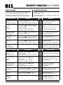
SIGNAL OUTPUTS CONDITION
PRIORITY
RANKING
REMARKS
DIGITAL MESSAGE
(DM-10)
M6 alert voice message
• Rear panel no.
J message rst priority S/W:
"ON" (close) SELECTOR
• Pack signal priority S/W (MS 2): "PRIORITY"
1
All signals closed.
Announcement only for M6
(alert voice message)
P.T.T MIC
CHIME
MODULES
• Pack signal priority S/W (MS 2): "PRIORITY"
• Rear panel no.
N remote receiver (RR-60)
slide S/W: "SLAVE"
• Slide S/W of VLM-100: "PRIORITY"
• Slide S/W of VLM-106/206: "SLAVE"
2
Output only for P.T.T MIC, Chime and
pack
(TP-10, CR-10, CDP-10, CDR-
10, DM-10) others will be closed
P.T.T MIC (VLM-100)
REMOTE CONTROL
(VLM-106/206)
• Rear panel no.
N remote receiver (RR-60)
slade S/W: "PRIORITY"
3
P.T.T MIC and REMOTE CONTROL
(VLM-106/206) activated
MIC 1, 2, 3
TEL PAGING
• Rear panel no.
A MIC PRIORITY S/W: "ON"
• Pack signal priority S/W (MS 2): "SLAVE"
4
Siren, ringer, line 4, 5 and
pack signals (modules) not activated
MIC 1, 2, 3
SIREN
• Rear panel no.
A MIC PRIORITY S/W: "OFF"
• Pack signal priority S/W (MS 2): "SLAVE"
5
Ringer, line 4, 5 and
pack signals (modules) not activated.
LINE 4, 5
TEL RINGER
MODULES (PACK)
–
no
Ringer, line 4, 5 and pack signals
(modules CR-10, TP-10, CDP-10M, …)
have no priority against other signals.
PRIORITÄTS FUNKTIONEN
Werkseinstellung des Prioritätsschalters MS 2 (hinter Modul-
leerfeldpaneel): "SLAVE".
Die folgende Tabelle gibt alle möglichen Prioritäten wieder
und ihre Rangfolge.
PRIORITY FUNCTION
When shipped it is factory preset as follows pack signal
priority switch (FRONT PCB MS 2): Setting at SLAVE.
The following is priority ranking against all signal inputs of
system and priority signal is "ON" "OFF" automatically.
SIGNAL AUSGÄNGE BEDINGUNGEN
RANG D.
PRIORITÄT
BEMERKUNGEN
DIGITAL TEXTMODUL
(DM-10)
Speicherbank Nr. 6
• Schalter an Klemme Nr.
J message rst
priority schließen
• Modul Signal Jumper MS 2 auf: "PRIORITY"
1
Alle anderen Signale sind geschlossen
P.T.T MIC (VLM-100)
GONG
MODULE
• Modul Signal Jumper MS 2 auf: "PRIORITY"
• Schalter Rückansicht Nr.
N (RR-60)
auf: "SLAVE"
• Schalter von VLM-100: "PRIORITY"
• Schalter v. VLM-106/206: "SLAVE"
2
Vorrang für P.T.T Mikrophon, Gong
und Module (TP-10, CR-10, CDP-10,
CDR-10, DM-10)
P.T.T MIC (VLM-100)
REMOTE CONTROL
(VLM-106/206)
• Schalter Rückansicht Nr.
N (RR-60)
auf: "PRIORITY"
• Schalter von VLM-100: "PRIORITY"
3
Vorrang für P.T.T Mikrophon
und REMOTE CONTROL
(VLM-105/205)
MIC 1, 2, 3
TEL PAGING
• Schalter Rückseite Nr.
1 auf: "ON" (PRIORITY)
• Modul Signal Jumper MS 2 auf: "SLAVE"
4
Night ringer, LINE IN 4, 5, Sirene
und Module sind untergeordnet
MIC 1, 2, 3
SIRENE
• Schalter Rückseite Nr.
1 auf: "OFF"
• Modul Signal Jumper MS 2 auf: "SLAVE"
5
Night ringer, LINE IN 4, 5
und Module sind untergeordnet
LINE 4, 5
TEL RINGER
MODULE
–
keine
Night ringer, LINE IN 4, 5
und Module wie CR-10, TP-10, CP-10,
usw., haben keine Priorität.
PRIORITY FUNCTION VLZ-SERIES

19
OUT
dB
AUX IN
-10dB
0
-10
PRIORITY
BUSY
G
AUDIO
17V
1357
2468
OFF
ON
AUDIO OUT
LINK
L
R
DATA
SLAVE PRIORITY
REMOTE CONTROLLER
MODEL NO.: VLM-206
MADE IN KOREA
SERIAL NO.:
VLM-206
Remote Controller
1
6
2
5
3
4
POWER
SEND
BUSY
REPEAT/STOP
START/STOP
DIGITAL MESSAGE
MESSAGE BANK
1 2 3 4 5 6
ALL
SPEAKER ZONES SELECTOR
TALK
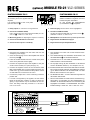
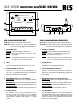
VLM-106/206 MICROPHONE DESK
VLM-106: to select and control 6 speaker zones.
VLM-206: to select and control 6 speaker zones, and for
remote control of the digital text module DM-10.
1. INDICATING LEDs
POWER: Power LED (amplier switched on)
SEND: lights up if a signal (announcement) are send
to amplifier.
BUSY: lights up if a signal (announcement) are send
to amplifier. Or if other in series connected
microphones send an announcement
2. TALK
Only when pressing "TALK", you can talk with prechime
signal. (activate Speakerline before on the mic. desk)
3. SPEAKER ZONES SELECTOR
Pressing one of the zone button delegates the si-
gnal to the desired loud speaker zone or for all zones
"ALL CALL". To speak and remote control of the Textmo-
dules at the same time are not possible.
4. DIGITAL MESSAGE (only model VLM-206)
START/STOP: activate and stop the digital text module
DM-10.
REPEAT/STOP: activate and stop the digital text module
DM-10 by repeating a time interval (adjustable at DM-10).
MESSAGE BANK:
To select one of the 6 recorded massages of the DM-10.
5. SLAVE/PRIORITY
For operating of 2 pcs more for VLM-106/206 simul-
taneously, one of VLM-106/206 can be set "PRIORI-
TY" and the other is set to "SLAVE". Then, even though
VLM-106/206 is operating under "SLAVE", if you push
"TALK".
VLM-106/206 MICROPHON-SPRECHSTELLE
VLM-106: zur Anwahl der 6 einzelnen Lautsprecherkreise.
VLM-206: zur Anwahl der 6 einzelnen Lautsprecherkreise und
zur Fernsteuerung des Digital-Textmoduls DM-10.
1. KONTROLLANZEIGEN
POWER: Betriebsanzeige (Verstärker eingeschaltet).
SEND: leuchtet, wenn Signale (Durchsagen) zum
Verstärker gesendet werden.
BUSY: leuchtet, wenn Signale (Durchsagen) zum Ver-
stärker gesendet werden, auch bei Durchsa-
gen von in Serie geschalteten Sprechstellen.
2. SPRECHTASTE
Nur bei gedrückter Taste kann gesprochen werden (vor-
her LS-Kreis an der Sprechstelle wählen).
3. LAUTSPRECHERKREIS WÄHLER
Mit diesen Tasten können die einzelnen Lautsprecher-
kreise oder "ALL CALL" ausgewählt werden. Fernbe-
dienung des Textmodules und gleichzeitig Sprechen ist
nicht möglich.
4. DIGITAL MESSAGE (nur bei Modell VLM-206)
START/STOP: aktiviert und stoppt das digitale Textmo-
dul DM-10.
REPEAT/STOP: aktiviert und stoppt das digitale Textmo-
dul DM-10 in einem Zeitintervall (einstellbar im DM-10).
MESSAGE BANK:
Zur Auswahl der 6 Speicherbänke des DM-10.
5. SLAVE/PRIORITY
Bei gleichzeitiger Benutzung von mehreren Sprechstel-
len (VLM-106/206) kann mit diesem Schalter der Vorrang
"PRIORITY" einer gewünschten Sprechstelle bestimmt
werden. Die anderen Sprechstellen (VLM-106/206) müs-
sen dann auf "SLAVE" stehen.
A
B 3
4
6 5 8 97
VLZ-SERIES MICROPHONE DESK VLM-106/206

20
6. DM-10 ON/OFF
Wenn der Schalter auf "OFF" steht ist es nicht möglich,
das digitale Textmodul (DM-10) anzusteuern.
7. OUT-LINK
Buchsen für 8-pol. Übertragungskabel, z.B. um weitere
VLM-106/206 in Serie anzuschließen.
8. AUX EINGANG
Cinchbuchsen ermöglichen Einschleifen von Audio-Si-
gnalen, z.B. CD-Player, Kassetten Deck, MP3 Player …
9. AUDIO OUT GAIN
Lautstärkeregler für Audio Ausgangs Signale.
PTT REMOTE
MODEL NO.: VLM-100A
MADE IN KOREA
VLM-100A
P.T.T Remote
TALK
CHIME
PRIORITY
P.T.T REMOTE
21
AUDIO OUT
CHIME
PRIORITY
G
1
4
3
5
2
7
6
LED PWR
1357
2468
24V
AUDIO
PRIORITY
CHIME
6. DM-10 ON/OFF
It‘s not possible to control the digital text module
(DM-10) if this is switched to "OFF" .
7. OUT-LINK
Sockets to attach 8-pin transmission cables, e.g. to con-
nect further VLM-106/206 in series.
8. AUX INPUT
AUX input for other audio signals, e.g. CD-Player, Tape
Decks, MP3-Player …
9. AUDIO OUT GAIN
This is audio output control volume.
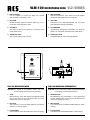
VLM-100 MICROPHONE DESK
VLM-100: for all-call to all speaker zones, with pre-
announcement chime and priority switching.
1. TALK
When pressing „TALK“ MIC signal is activated and make
input of DC 24V from the crew terminal NO. 2 of main
amplier and priority is activated.
2. DIN JACK
This consists of 7 pins use shield cable for microphone
(cable is in scope of supply).
3. RJ45 SOCKET
RJ45 socket for patch cable (cable is in scope of supply).
VLM-100 MICROPHON-SPRECHSTELLE
VLM-100: für den Sammelruf auf allen Lautsprecherkreisen,
mit Vorgong und Prioritäts-Schaltung.
1. SPRECHTASTE
Bei Betätigung des Tastschalters 1 kann gesprochen
werden, weiterhin wird der Vorgong und die Priorität akti-
viert (wenn Schalter auf „ON“).
2. DIN-BUCHSE
7-pol. DIN-Buchse für Mikrophonkabel (Kabel im Liefer-
umfang).
3. RJ45-BUCHSE
RJ45-Buchse für Patchkabel (Kabel im Lieferumfang).
A
BC
VLM-100 MICROPHONE DESK VLZ-SERIES
Seite wird geladen ...
Seite wird geladen ...
Seite wird geladen ...
Seite wird geladen ...
-
 1
1
-
 2
2
-
 3
3
-
 4
4
-
 5
5
-
 6
6
-
 7
7
-
 8
8
-
 9
9
-
 10
10
-
 11
11
-
 12
12
-
 13
13
-
 14
14
-
 15
15
-
 16
16
-
 17
17
-
 18
18
-
 19
19
-
 20
20
-
 21
21
-
 22
22
-
 23
23
-
 24
24


RCS VLZ-6120A-6240A-6480A-6600A Bedienungsanleitung
- Kategorie
- Audioverstärker
- Typ
- Bedienungsanleitung
in anderen Sprachen
Verwandte Artikel
-
RCS VLZ-6480 A Operating Instructions Manual
-
-
-
-
-
-
-
-
-
RCS BA-600 DP Bedienungsanleitung
Andere Dokumente
-
Allen + Roth 1541VA-48-201-901 Dimensions Guide
-
Audio international PA-480-01-x Benutzerhandbuch
-
 UNIELECTRONIC UMA 7120PB Benutzerhandbuch
-
DYNACORD MV 503 Benutzerhandbuch
-
Monacor PA-1500D Benutzerhandbuch
-
Ultrak KAB 2060M Benutzerhandbuch
-
Ecler ENVIRO CM04-08-12 Benutzerhandbuch
-
Extron VoiceLift Pro Microphone Spezifikation
-
TOA A-1806 UK Schnellstartanleitung
-
Zeck-audio Mela Bedienungsanleitung
