
OPERATING INSTRUCTIONS / BEDIENUNGSANLEITUNG
VLM-100/106/206
REMOTE MICROPHONE
- ENGLISH
- DEUTSCH

VLM-100/106/206
2
OUT
dB
AUX IN
-10dB
0
-10
PRIORITY
BUSY
G
AUDIO
17V
1357
2468
OFF
ON
AUDIO OUT
LINK
L
R
DATA
SLAVE PRIORITY
REMOTE CONTROLLER
MODEL NO.: VLM-206
MADE IN KOREA
SERIAL NO.:
VLM-206
Remote Controller
1
6
2
5
3
4
POWER
SEND
BUSY
REPEAT/STOP
START/STOP
DIGITAL MESSAGE
MESSAGE BANK
1 2 3 4 5 6
ALL
SPEAKER ZONES SELECTOR
TALK
VLM-106/206 MICROPHONE DESk
VLM-106: to select and control 6 speaker zones.
VLM-206: to select and control 6 speaker zones, and for
remote control of the digital text module DM-10.
1. INDICATING LEDs
POWER: Power LED (amplifier switched on)
SEND: lights up if a signal (announcement) are send
to amplifier.
BUSY: lights up if a signal (announcement) are send
to amplifier. Or if other in series connected
microphones send an announcement
2. TALK
Only when pressing "TALK", you can talk with prechime
signal. (activate Speakerline before on the mic. desk)
3. SPEAKER ZONES SELECTOR
Pressing one of the zone button delegates the si-
gnal to the desired loud speaker zone or for all zones
"ALL CALL". To speak and remote control of the Textmo-
dules at the same time are not possible.
4. DIGITAL MESSAGE (only model VLM-206)
START/STOP: activate and stop the digital text module
DM-10.
REPEAT/STOP: activate and stop the digital text module
DM-10 by repeating a time interval (adjustable at DM-10).
MESSAGE BANK:
To select one of the 6 recorded massages of the DM-10.
VLM-106/206 MICROPHON-SPRECHSTELLE
VLM-106: zur Anwahl der 6 einzelnen Lautsprecherkreise.
VLM-206: zur Anwahl der 6 einzelnen Lautsprecherkreise und
zur Fernsteuerung des Digital-Textmoduls DM-10.
1. KONTROLLANZEIGEN
POWER: Betriebsanzeige (Verstärker eingeschaltet).
SEND: leuchtet, wenn Signale (Durchsagen) zum
Verstärker gesendet werden.
BUSY: leuchtet, wenn Signale (Durchsagen) zum Ver-
stärker gesendet werden, auch bei Durchsa-
gen von in Serie geschalteten Sprechstellen.
2. SPRECHTASTE
Nur bei gedrückter Taste kann gesprochen werden (vor-
her LS-Kreis an der Sprechstelle wählen).
3. LAUTSPRECHERKREIS WÄHLER
Mit diesen Tasten können die einzelnen Lautsprecher-
kreise oder "ALL CALL" ausgewählt werden. Fernbe-
dienung des Textmodules und gleichzeitig Sprechen ist
nicht möglich.
4. DIGITAL MESSAGE (nur bei Modell VLM-206)
START/STOP: aktiviert und stoppt das digitale Textmo-
dul DM-10.
REPEAT/STOP: aktiviert und stoppt das digitale Textmo-
dul DM-10 in einem Zeitintervall (einstellbar im DM-10).
MESSAGE BANK:
Zur Auswahl der 6 Speicherbänke des DM-10.
A
B 3
4
6 5 8 97

VLM-100/106/206
3
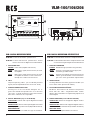
5. SLAVE/PRIORITY
Bei gleichzeitiger Benutzung von mehreren Sprechstel-
len (VLM-106/206) kann mit diesem Schalter der Vorrang
"PRIORITY" einer gewünschten Sprechstelle bestimmt
werden. Die anderen Sprechstellen (VLM-106/206) müs-
sen dann auf "SLAVE" stehen.
6. DM-10 ON/OFF
Wenn der Schalter auf „OFF“ steht ist es nicht möglich,
das digitale Textmodul (DM-10) anzusteuern.
7. OUT-LINK
Buchsen für 8-pol. Übertragungskabel, z.B. um weitere
VLM-106/206 in Serie anzuschließen.Als Spannungsver-
sorgung nur 17V von den VLA- und VLZ-Modellen an-
schliessen.
8. AUX EINGANG
Cinchbuchsen ermöglichen Einschleifen von Audio-Si-
gnalen, z.B. CD-Player, Kassetten Deck, MP3 Player …
9. AUDIO OUT GAIN
Lautstärkeregler für Audio Ausgangs Signale.
PTT REMOTE
MODEL NO.: VLM-100
MADE IN KOREA
VLM-100
P.T.T Remote
TALK
CHIME
PRIORITY
P.T.T REMOTE
21
AUDIO OUT
CHIME
PRIORITY
G
1
4
3
5
2
7
6
LED PWR
5. SLAVE/PRIORITY
For operating of 2 pcs more for VLM-106/206 simul-
taneously, one of VLM-106/206 can be set "PRIORI-
TY" and the other is set to "SLAVE". Then, even though
VLM-106/206 is operating under "SLAVE", if you push
"TALK".
6. DM-10 ON/OFF
It‘s not possible to control the digital text module
(DM-10) if this is switched to „OFF“ .
7. OUT-LINK
Sockets to attach 8-pin transmission cables, e.g. to
connect further VLM-106/206 in series. For power
supply connected only the 17V by the VLA- and VLZ mo-
dels.
8. AUX INPUT
AUX input for other audio signals, e.g. CD-Player, Tape
Decks, MP3-Player …
9. AUDIO OUT GAIN
This is audio output control volume.
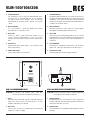
VLM-100 MICROPHONE DESk
VLM-100: for all-call to all speaker zones, with pre-
announcement chime and priority switching.
1. TALK
When pressing „TALK“ MIC signal is activated and make
input of DC 24V from the crew terminal NO. 2 of main
amplifier and priority is activated.
2. DIN JACK
This consists of 7 pins use shield cable for microphone
(cable is in scope of supply).
VLM-100 MICROPHON-SPRECHSTELLE
VLM-100: für den Sammelruf auf allen Lautsprecherkreisen,
mit Vorgong und Prioritäts-Schaltung.
1. SPRECHTASTE
Bei Betätigung des Tastschalters 1 kann gesprochen
werden, weiterhin wird der Vorgong und die Priorität ak-
tiviert (wenn Schalter auf „ON“).
2. DIN-BUCHSE
7-pol. DIN-Buchse für Mikrophonkabel (Kabel im Liefer-
umfang).
A
B

VLM-100/106/206
© Copyright by RCS AUDIO-SYSTEMS GmbH. Veröffentlichung und Vervielfältigung der enthaltenen Daten, auch auszugsweise, nur mit unserer Genehmigung. © Copyright by RCS AUDIO-SYSTEMS GmbH. Veröffentlichung und Vervielfältigung der enthaltenen Daten, auch auszugsweise, nur mit unserer Genehmigung.
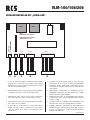
VERDRAHTUNGSPLAN MIT „VARIO-LINE“
• •
RJ45
RR-60
DIGITALE SCHNITTSTELLE
VERDRAHTUNGSPLAN MIT
„VARIO-LINE“ 6-Zonen
CN801 AS802 AS903 AS204 AS 4-1
N.C +17 GA/O R/M PTT CH Z6 RE 5 4 3 2 1
BY
CM
ST
RE
M
1
M
2
M
3
M
4
M
5
RR-60
(REMOTE REV.)
SW801 - PRI S/W
RJ45
1. 2. 3. 4. 5.
1. Anschluss für Spannungsversorgung (+17V) vom Netz-
teil (Stecker AS-801). Lösen Sie dazu den Kabelbinder
im hinteren Teil des Gerätes und stecken den freien Ste-
cker (Kabel rot, schwarz) in die Buchse CN-801 des Mo-
dules RR-60.
2. Abgeschirmtes Audio-Kabel zur Verbindung mit Ein-
gangsplatine (Rückseite, Buchse AN802, freie 2-polige
Buchse oben auf Eingangsplatine).
3. Kabel (schwarz, weiss, rot) zur Verbindung mit PTT-Plati-
ne (Rückseite, Platine mit 7-poliger DIN-Buchse, Buchse
CN903, 3-polig).
4. 7-poliges Kabel zur Verbindung mit Relaisplatine (Vor-
derseite rechts oben, freie 7-polige Buchse CN901).
5. 10-poliges Kabel zur Verbindung mit Textmodul DM-10
(Digital Message). Kabel wird auf Textmodul auf Buch-
se CN4-1 angeschlossen. Ist kein Textmodul eingebaut
bleibt dieses Kabel frei.
RCS01.03.2011
1. Connection for power supply (+17 V) from the power supply
(plug AS-801). Loosen the tie in the back of the unit and
plug the free connectors (cable red, black) into the socket
CN-801 of the module RR-60.
2. Shielded audio cable for connecting to input board (back,
jack AN802, free 2-pin socket on top input board).
3. Cable (black, white, red) to connect to PTT board (rear
panel with 7-pin DIN socket, socket CN903, 3-pole).
4. 7-pin cable for connection to relay board (front top right,
free 7-pin connector CN901).
5. 10-pin cable for connecting text module with DM-10
(digital message). Cable is connected to a text module
connector CN4-1. If no module is installed this cable
remains free.
-
 1
1
-
 2
2
-
 3
3
-
 4
4


in anderen Sprachen
- English: RCS VLM-100-206 Owner's manual
Verwandte Artikel
-
RCS VLM-100-205 Bedienungsanleitung
-
-
RCS VLZ-6120A-6240A-6480A-6600A Bedienungsanleitung
-
-
-
-
-
-
-