
OPERATING INSTRUCTIONS / BEDIENUNGSANLEITUNG
- ENGLISH
- DEUTSCH
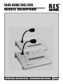
VLM-100A/105/205
REMOTE MICROPHONE

2
VLM-100A/105/205
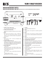
reMote Microphone VLM105
reMote Microphone VLM 205
(identisch Mit VLM-105, jedoch Mit Fernbedienung Für digitAL MessAge dMt-10)
1. POWER (STATUS INDICATOR)
Turn on the power, LED indicator lights.
2. SEND (STATUS INDICATOR)
Incasedataaresuppliedtoamplier,sendLEDindicator
lights.
3. BUSY
Busy means under operating of "TALK" or digital mes-
sage. Also, when using remote controller, if you select
"SLAVE" of NO. 8, remote controller is not operated un-
der busy LED.
4. TALK
When pressing "TALK", you talk via microphone with
prechime signal.
5. SPEAKER ZONES SELECTOR
Pressing one of the zone button delegates the signal to
the desired loud speaker zone. Then, attenuation func-
tionsinthemainamplierareresetandzonepower-out
is converted to HI impedance power output.
6. DIGITAL MESSAGE
- START/STOP
Message start and stop. This makes you replay, stop re-
corded message of the memory bank (M1-M6) one time
without setting repeat function.
- REPEAT/STOP
You can replay or stop by repeat setting and time inter-
val.
- MESSAGE BANK (M1-M6)
Message bank lets you select recorded bank.
1. POWER
Diode zeigt Betriebsbereitschaft an
2. SEND
Diode leuchtet, wenn Signale zum Verstärker gesendet
werden.
3. BUSY
Diode leuchtet, wenn Signale zum Verstärker gesendet
werden, auch von in Serie geschalteten anderen Sprech-
stellen.
4. TALK
Sprechtaste : Nur bei gedrückter Taste kann gesprochen
werden. (vorher LS-Kreis aktivieren)
5. SPEAKER ZONES SELECTOR
Mit diesen Tasten können die einzelnen Lautsprecher-
kreise und "ALL CALL" ausgewählt werden. Der Laut-
sprecherkreis sollte vor dem Sprechen gewählt werden.
Fernbedienung des Textmodules und gleichzeitig Spre-
chen ist nicht möglich.
6. DIGITAL MESSAGE (nur bei Modell VLM-205)
- START/STOP
Mit diesem Taster wird das digitale Textmodul DMT-10
aktiviert und gestoppt.
- REPEAT/STOP
Mit diesem Taster wird das digitale Textmodul in einem
Zeitintervall (einstellbar im DMT-10) aktiviert und ge-
stoppt.
- MESSAGE BANK (M1-M6)
Drehschalter zur Auswahl der 6 Speicherbänke des
DMT-10.

VLM-100A/105/205
3
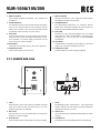
7. DMT-10 ON/OFF
"ON" position for DMT-10 operating, "OFF" position not
for DMT-10.
8. SLAVE/PRIORITY
For operating of 2pcs more for VLM-105/205 simultane-
ously, one of VLM-105/205 can be set priority and the
other is set to SLAVE. Then, even though VLM-105/205
is operating under SLAVE, if you push "TALK".
9. OUT-LINK
This is RJ45 connector for power supply of audio, data,
make sure that 4 pairs LAN cable is necessary for opti-
mum operation. For power supply connected only the
17V by the VLA- and VLZ models.
10. AUX INPUT
AUX input is for cassette deck or other same products.
11. AUDIO OUT GAIN
This is audio output control volume
7. DMT-10 ON/OFF
Wenn der Schalter auf "OFF" steht ist es nicht möglich,
das digitale Textmodul anzusteuern.
8. SLAVE/PRIORITY
Bei gleichzeitiger Benutzung von mehreren Sprech-
stellen kann mit diesem Schalter der Vorrang einer ge-
wünschten Sprechstelle bestimmt werden.
9. OUT-LINK
Buchsen für 8-pol. Übertragungskabel z.B. um weitere
VLM-105/205 in Serie anzuschließen. Als Spannungs-
versorgung nur 17V von den VLA- und VLZ-Modellen
anschliessen.
10. AUX INPUT
Chinchbuchsen ermöglichen Einschleifen von Audio-Si-
gnalen, z.B. CD-Player, Kassetten Deck u.ä.
11. AUDIO OUT GAIN
Lautstärkeregler für Audio Ausgangs Signale.
p.t.t. reMote VLM-100A
1. TALK
When pressing „TALK“ MIC signal is activated and make
input of DC 24V from the crew terminal NO. 2 of main
amplierandpriorityisactivated.
2. DIN JACK
This consists of 7 pins use shield cable for microphone
(cable is in scope of supply).
3. RJ45-Socket
RJ45-Socket for patch cable (cable is in scope of supply).
1. TALK
Bei Bestätigung des Tastschalters 1 kann gesprochen
werden, weiterhin wird der Vorgong und die Priorität ak-
tiviert (wenn Schalter auf „ON“).
2. DIN-Buchse
7-pol. DIN-Buchse für Mikrophonkabel (Kabel im Liefer-
umfang).
3. RJ45-Buchse
RJ45-Buchse für Patchkabel (Kabel im Lieferumfang).
PTT REMOTE
MODEL NO.: VLM-100A
MADE IN KOREA
VLM-100A
P.T.T Remote
TALK
CHIME
PRIORITY
P.T.T REMOTE
21
AUDIO OUT
CHIME
PRIORITY
G
1
4
3
5
2
7
6
LED PWR
1357
2468
24V
AUDIO
PRIORITY
CHIME
A
BC

VLM-100A/105/205
© Copyright by RCS AUDIO-SYSTEMS GmbH. Veröentlichung und Vervielfältigung der enthaltenen Daten, auch auszugsweise, nur mit unserer Genehmigung.
©CopyrightbyRCSAUDIO-SYSTEMS GmbH.VeröentlichungundVervielfältigungderenthaltenenDaten, auchauszugsweise, nurmitunsererGenehmigung.
RCS27.07.2015
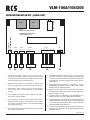
1. Anschluss für Spannungsversorgung (+17V) vom Netz-
teil (Stecker AS-801). Lösen Sie dazu den Kabelbinder
im hinteren Teil des Gerätes und stecken den freien Ste-
cker (Kabel rot, schwarz) in die Buchse CN-801 des Mo-
dules RR-10.
2. Abgeschirmtes Audio-Kabel zur Verbindung mit Ein-
gangsplatine (Rückseite, Buchse AN802, freie 2-polige
Buchse oben auf Eingangsplatine).
3. Kabel (schwarz, weiss, rot) zur Verbindung mit PTT-Pla-
tine (Rückseite, senkrechte Platine mit 2 RJ45-Buchsen,
Buchse CN903, 3-polig).
4. 6-poliges Kabel zur Verbindung mit Relaisplatine (Vor-
derseite rechts oben, freie 6-polige Buchse CN901).
5. 10-poliges Kabel zur Verbindung mit Textmodul DMT-10
(Digital Message). Kabel wird auf Textmodul auf Buchse
18 (Remote Control) angeschlossen. Ist kein Textmodul
eingebaut bleibt dieses Kabel frei.
6. Jumper E/M; Bei Aktivierung auf ON kann die Speicher-
bank M6 vom Textmodul mit der Sprechstelle VLM-205
gestartet werden.
1. Connection for power supply (+17 V) from the power
supply (plug AS-801). Loosen the tie in the back of the
unit and plug the free connectors (cable red, black) into
the socket CN-801 of the module RR-10.
2. Shielded audio cable for connecting to input board
(back, jack AN802, free 2-pin socket on top input board).
3. Cable (black, white, red) to connect to PTT board (rear
panel with 2 piece of RJ45-sockets, socket CN903,
3-pole).
4. 6-pin cable for connection to relay board (front top right,
free 6-pin connector CN901).
5. 10-pin cable for connecting text module with DMT-10
(digital message). Cable is connected to a text module
connector (18. Remote Control). If no module is installed
this cable remains free.
6. Jumper E/M; Set to ON for starting M6 from DMT-10 with
the microphone VLM-205.
VerdrAhtungspLAn Mit „VArio-Line“
• •
RJ45
CN801 AS802 AS903 AS204 AS 4-1
N.C +17 GA/O R/M PTT CH Z6 RE 5 4 3 2 1
E/M
OFF ON
BY
CM
ST
RE
M
1
M
2
M
3
M
4
M
5
RR-10
(REMOTE REV.)
SW801 - PRI S/W
RJ45
1. 2. 3. 4. 5. 6.
• • •
RR-10
DIGITALE SCHNITTSTELLE
VERDRAHTUNGSPLAN MIT
„VARIO-LINE“ 5-Zonen
-
 1
1
-
 2
2
-
 3
3
-
 4
4


in anderen Sprachen
- English: RCS VLM-100A-205 Owner's manual
Verwandte Artikel
-
RCS VLM-100-205 Bedienungsanleitung
-
-
-
-
RCS VLZ-6120A-6240A-6480A-6600A Bedienungsanleitung
-
-
-
-
-