Seite wird geladen ...

OPERATING INSTRUCTIONS / BEDIENUNGSANLEITUNG
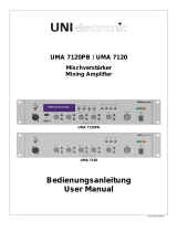
VLA-601 A / 602 A
10-ZONE/20-ZONE »VARIO-LINE«
- ENGLISH
- DEUTSCH
VLA-601 A
VLA-602 A

2
Electromagnetic compatibility and low-voltage guidelines: RCS leaves all devices and products, which are subject to the CE guidelines by certified test laboratories test.
By the fact it is guaranteed that you may sell our devices in Germany and in the European Union domestic market without additional checks.
Elektromagnetische Verträglichkeit und Niederspannungsrichtlinien: RCS läßt alle Geräte und Produkte, die den CE-Richtlinien unterliegen durch zertifizierte Prüflabors
testen. Dadurch ist sichergestellt, dass Sie unsere Geräte in Deutschland und im EU-Binnenmarkt ohne zusätzliche Prüfungen verkaufen dürfen.
AUSPACKEN UND KONTROLLE DES PRODUKTS
Bitte überprüfen Sie das Gerät sofort auf evtl. Transportschä-
den. Jedes RCS Produkt wird vor dem Verpacken sorgfältig
überprüft und in einem speziell dafür vorgesehenen Karton
geliefert.
Alle Transportschäden müssen sofort bei der Transport-
firma reklamiert werden!
Rücksendung: Wenn es nötig sein sollte ein defektes Gerät
zurückzusenden, nehmen Sie bitte Kontakt mit Ihrem Händ-
ler auf. Bitte versenden sie alle Rücksendungen in der Origi-
nalverpackung.
INSPECTION AND INVENTORY OF THE PRODUCT
Check unit carefully for damage which may have occurred
during transport. Each RCS product is carefully inspected at
the factory and packed in a special carton for safe transport.
Notify the freight carrier immediately if you observe any
damage to the shipping carton or product!
Return: Repack the unit in the carton and await inspection
by the carrier’s claim agent. Notify your dealer of the pending
freight claim. Returning your unit for service or repairs.
Should your unit require service, contact your dealer.
WICHTIGE SICHERHEITSHINWEISE
Bitte lesen Sie die Sicherheitsanweisungen, bevor Sie
das Gerät in Betrieb nehmen.
1. Installation nach folgenden Richtlinien:
• Stellen Sie das Gerät immer auf eine ebene und stabile
Unterfläche.
• Wählen Sie eine trockene Umgebung und vermeiden Sie
Aufstellungsorte mit geringer Luftzufuhr.
• Vermeiden Sie die direkte Nähe zu Heizungen und ande-
ren Hitzequellen.
• Bei Einbau in einen 19“ Gestellschrank ordnen Sie die
Geräte so an, daß eine ausreichende Belüftung gewähr-
leistet wird.
2. Bitte beachten Sie folgendes, wenn Sie das Gerät
anschließen:
• Um Bedienfehler zu vermeiden, lesen Sie bitte zuerst die
Anleitung sorgfältig.
• Öffnen Sie niemals das Gehäuse, ohne vorher den Netz-
stecker zu ziehen.
• Schließen Sie das Gerät nur an 230 V Netzspannung und
an die 24 V Notstromversorgung (DC).
SAFETY INSTRUCTION
Please read all safety instructions before operating the
Device.
1. Installation according to the following guidelines:
• Install the device always on a flat and even surface.
• The device should not be exposed to damp or wet
surroundings. Please keep away from water.
• Please avoid using the device near heat sources, such as
radiators or other devices which produce heat.
• To install the device in a 19” rack please note that the ap-
pliance should be situated, that the location or position
does not interfere with an adequate ventilation.
2. Keep in mind the following when connecting the
device:
• Connect the amplifier after reading the manuals.
• To prevent electric shock, do not open top cover.
• Connect only to 230 V and 24 V Emergency power (DC).
CAUTION / ACHTUNG
CAUTION: TO REDUCE THE RISK OF ELECTRIC SHOCK DO NOT REMOVE
COVER (OR BACK) NO USER-SERVICEABLE PARTS INSIDE REFER
SERVICING TO QUALIFIED PERSONNEL.
ACHTUNG: ZUR VERMEIDUNG VON STROMSCHLÄGEN GEHÄUSEAB-
DECKUNG ODER RÜCKSEITE NICHT ENTFERNEN. KEINE VOM BENUT-
ZER WARTENDEN TEILE IM INNEREN. WARTUNG NUR DURCH QUALIFI-
ZIERTEM PERSONAL.
SAFETY INSTRUCTIONS VLA-601A/602A

3
VLA-601A/602A CONTENTS
VLA-601 A / VLA-601 A
GENERAL REFERENCES / ALLGEMEINE HINWEISE
.......................................... 2
FEATURES / HAUPTMERKMALE
........................................................... 4
MOUNTING & COOLING / MONTAGE & KÜHLUNG
........................................... 5
VLA-601A/602A FRONT PANEL / FRONTANSICHT
.......................................6-7
VLA-601A/602A REAR VIEW / RÜCKANSICHT
........................................ 8-10
VLZ-SERIES PRIORITY FUNCTIONS / PRIORITÄTS FUNKTIONEN
.......................11
VLA-601A/602A CASCADING WITH AMPLIEFIERS / KASKADIERUNG MIT VERSTÄRKERN
....12
VLM-200 A MICROPHONE DESK / MICROPHON-SPRECHSTELLE
......................12
VLA-601A/602A SPECIFICATIONS / TECHNISCHE DATEN
.................................13
VLA-601 A BLOCK DIAGRAM / BLOCKSCHALTBILD
.................................14
VLA-602 A BLOCK DIAGRAM / BLOCKSCHALTBILD .................................15
CONTENTS / INHALT

4
MAIN FEATURES
• Automatic variable speed fan
• Over current protection
• Over heating protection
• Load short circuit protection
• Built in l.P.F. ( Low pass filter ) circuit
• Output led indicator
• 10 or 20 Zone speaker output or all call
• Speaker attenuator per channel by 5 step (VLA-601 A only)
FURTHER FEATURES
• Input gain volume control per microphone
• Selective phantom power per microphone
• RJ45 connecter for P.T.T. Microphone (VLM-200) input
• Rca jack for LINE 4, 5 input
• Rca jack for RECording output
• Connect for PRE-OUT/external AMP IN
• Equalizer per input channel
• Telephone PAGING and NIGHT RINGER
• 2- Or 4-tone chime
(switchable with jumper ms 1)
• Siren switachble to alarme tone
• Optional module connection
(TP-10 USB, DMT-10, CDP-10 USB, CDR-10 USB)
• Remote control for POWER ON/OFF
• SOFT START for battery power supply delay
• Remote control system by RJ45 connector
1. Digital message
2. Chime
3. Connection with up to 3 VLM-210/220 simultaneously
• Auto alert announcement and AUTO POWER "ON"
Connecting to digital message (DMT-10)
(Message first priority connecting with fire alarm)
• Mic 1, 2, 3 priority selector switch
HAUPTMERKMALE
• Automatische Anpassung der Lüftergeschwindigkeit
• Kurzsschlußschutz
• Überhitzschutz
• Leerlaufschutz
• Low Pass Filter
• Ausgang LED- Pegel Anzeige
• 10 bzw. 20 Lautsprecherkreise und Summe
• Lautstärkereglung pro Kreis in 5 Stufen (nur VLM-601 A)
WEITERE MERKMALE
• MIC-Eingänge mit Gain-Regler ( Combo-Buchsen )
• Wahlweise Phantom-Power
• RJ45-Buchse für P.T.T. Microphon (VLM-200)
• Cinch-Buchsen für LINE-Eingänge 4,5
• Cinch-Buchse für REC Output,unsymm., 0 db
• PRE-OUT und AMP IN Klinkenbuchsen, 6,3 mm
• Für jeden Eingang Bass und Höhenregelung
• TEL-IN für PAGING IN und NIGHT RINGER
• Elektronischer 2- oder 4-Klanggong
(umstellbar mit Jumper MS 1 unter Leerblende)
• Sirene umschaltbar auf Alarmton
• Leerfeld für optionale Tonträgermodule
(TP-10 USB, DMT-10, CDP-10 USB, CDR-10 USB)
• Fernbedienung für POWER "ON/OFF"
• SOFT START
• Fernsteuerung über digitale Schnittstelle RJ45
1. Digitales Textmodul (Option)
2. Vorgong
3. Verbindung von mehreren VLM-210/220 gleichzeitig
• AUTO POWER "ON" und automatische Alarmdurchsage
über digitales Textmodul DMT-10
(Priorität von Durchsage und Feueralarm möglich)
• Schalter für Priorität von MIC-1, 2 und 3
FEATURES VLA-601A/602A

5
MOUNTING
Amplifier racking size for VLA-601A/602A are designed for
standard 19˝ rack mounting with additional left, right bracket.
Please pay close attention to the cooling requirements.
COOLING
Never block the air vents in the sides makes enough space
line 44 mm of the amplifier the following is figure of air-flow.
Check inside temperature of rack system so as not to be
more than 40°C for the stable operating in any case, we re-
commend you to install cooling fan additionally on the rear
panel of rack cabinet.
MONTAGE
Die Verstärker VLA-601A/602A sind mit seitlichen Befesti-
gungwinkeln für den Einbau in 19˝ Gestelle geeignet. Achten
sie aber darauf die Kühlungsöffnungen nicht zu verdecken.
KÜHLUNG
Blockieren sie nie die Luftöffnungen an den Seiten (min. 44
mm Raum), um einen optimalen Kühlluftfluß zu gewährlei-
sten. Falls sie die Verstärker in ein 19"-Rack einbauen und
immer mit höchster Leistung arbeiten, sollte gegebenenfalls
in das Rack ebenfalls ein entsprechender Lüfter eingebaut
werden.
INSIDE AIR FLOW
IMPORTANT:Be sure rear of amplifier
is securely mounted to rack.
AMPLIFIER
(TOP VIEW)
4in(10cm)MIN
RACK
CABINET
2.4in(6cm)MIN
RACK MOUNT SPACE
AIR FLOW IN RACK CABINET
AIR FLOW
EQUIPMENT
RACK
(SIDE VIEW)
BLOWER
AIR
FLOW
AIR
FLOW
BLOWER
DOOR
FRONT
OF RACK
PROTECTPROTECT FAULTFAULT
AUTOMATIC VARIABLE SPEED FAN
OFF OFF OFF OFF OFF
OFF OFF OFF OFF OFF
Z 6 Z 7 Z 8 Z 9 Z 10
Z 1 Z 2 Z 3 Z 4 Z 5
VLA-601 A
10 ZONE MIXING AMPLIFIER
VLA-601A/602A MOUNTING & COOLING

6
FRONTANSICHT VLZ-SERIE
1. MIC / LINE LEVEL
Regler: P.T.T 1 / EQ Regler
P.T.T 1 Regler für Lautstärke und EQ Regler für Tiefen
sowie Höheneinstellung des Eingang 1 und des P.T.T
REMOTE Eingang, (VLM-200) immer in Verbindung mit
"MASTER" Regler. Die LED Anzeige sollte nicht über "0"
ansteigen.
WICHTIG: Falls die Prioritätsfunktion aktiviert ist, können
nur Signale die auf dem Eingang 1 bzw. P.T.T REMOTE
(RJ-45-Buchse) anliegen, empfangen werden.
Die Eingänge 4, 5, NIGHT RINGER, PAGING IN und alle
Modulsignale (außer DMT-10) sind gesperrt, vorausge-
setzt der Jumper MS 2 (hinter Abdeckpaneel des Modul-
leerfeldes) steht auf "SLAVE".
Diese Prioritätsfunktion besteht nicht , wenn der Schalter
der Sprechstelle (VLM-200) auf "SLAVE" steht.
Regler: R.M. 2 Volume / EQ Regler
Remote 2 Regler für Lautstärke und EQ Regler für Tie-
fen sowie Höheneinstellung des Eingang 2 und digitale
Sprechstellen (VLM-210/220) - immer in Verbindung mit
"MASTER" Regler.
WICHTIG: Falls die Priorität aktiviert ist, können nur Si-
gnale die auf dem Eingang 2 anliegen, empfangen wer-
den. Die Eingänge 4, 5, Night Ringer, Paging In und alle
Modulsignale (außer DMT-10) sind gesperrt, vorausge-
setzt der Jumper MS 2 steht auf "SLAVE".
Regler: 3 Volume / EQ Regler 3
Regler 3 für Lautstärke und EQ Regler für Tiefen sowie
Höheneinstellung des Eingang 3 - immer in Verbindung
mit "MASTER" Regler.
WICHTIG: Falls die Priorität aktiviert ist, können nur Si-
gnale die auf dem Eingang 3 anliegen, empfangen wer-
den, vorausgesetzt der Jumper MS 2 steht auf "SLAVE".
2. LINE / LEVEL
Regler LINE LEVEL für Lautstärke und EQ Regler für Tie-
fen sowie Höheneinstellung der Eingänge 4 und 5 - im-
mer in Verbindung mit "MASTER" Regler.
PROTECTPROTECT
VLA-601A
10 ZONE MIXING AMPIFIER
OFF
OFF OFF OFF OFF
OFF
OFF OFF OFF OFF
Z 6 Z 7 Z 8 Z 9 Z 10
Z 1 Z 2 Z 3 Z 4 Z 5
OUTPUT
LEVEL
OFF
OFF OFF OFF OFF
OFF
OFF OFF OFF OFF
Z
6
Z 7 Z
8
Z 9 Z 10
Z
1
Z 2 Z
3
Z
4
Z 5
PAGING
A B 7
FRONT PANEL VLA-601A/602A
1. MIC / LINE LEVEL
Control: P.T.T 1 Volume / EQ Control
P.T.T 1 volume control / EQ control let you adjust in-
put 1level and P.T.T remote (VLM-200) level. BASS and
TREBLE CONTROLS make you adjusted equalizer so
as to suit for surrounding usually, first, position adjusted
should be set at "0" of LED indicator with two 0`clock of
MASTER volume. Second, you can increase input volu-
me to the position "0" of LED indicator.
IMPORTANT NOTE: In case the priority function is
activated, if you supply signal to MIC/LINE 1, then, all
signals including LINE 4, 5, PAGING RINGER and
module signals will be closed ,set Jumper MS 2 on the
FRONT PCB to "SLAVE".
But if you select switch of remote controller to "SLAVE",
signal of remote control will be cut-off.
Control: R.M. 2 / EQ Control
Remote 2 volume control / EQ control let you adjust input
2 level and remote controller (VLM-210/220) level. This
always in connection with “MASTER” controller. Bass
and treble controls make you adjusted equalizer.
IMPORTANT NOTE: In case the priority function is acti-
vated, if you supply signal to MIC/LINE 2, then, all signals
including LINE 4, 5, PAGING RINGER and module signals
(except DMT-10) will be closed, set Jumper MS 2 on the
FRONT PCB to "SLAVE".
Control: 3 Volume / EQ Control
3 volume control / EQ control let you adjust input 3 le-
vel. Bass and treble controls make you adjusted sound`s
color so as to suit for surrounding.
IMPORTANT NOTE: In case the priority function is acti-
vated, supply signal to MIC/LINE 3, then, all signals will be
closed, set Jumper MS 2 on the FRONT PCB to "SLAVE".
2. LINE LEVEL
LINE level volume control makes you adjusted line input
level and bass & treble make you adjust sound color.
JK 9
H6543
FRONT PANEL VLA-601A/602A

7
3. EQ-REGLER
Regler für Tiefen- sowie Höheneinstellung eines Einbau-
moduls, z.B. CDR-10 USB, DMT-10, etc.
4. GONG
Taster zur Gongauslösung und Lautstärkeregler.
5. TELEPHONE PAGING
Lautstärkeregler für "Paging-Eingang“. Wenn der Laut-
stärkeregler auf "LEAK" steht, wird eine Dämpfung von
-20 dB erreicht.
6. SIRENE
Tastschalter für auf- und abschwellende Sirene. Tast-
schalter für Dauerton und Lautstärkeregler.
7. MASTER
"MASTER" Lautstärkeregler. Alle Signale ob Module, Si-
rene, Mikrophone usw. können nur über den jeweiligen
Lautstärkeregler und den "MASTER" Regler eingestellt
werden.
8. POWER
Power Ein/Aus Schalter. Leuchtdioden für „STAND BY“
und „POWER“.
9. Output Level LED‘s
Die „0“ der Output Level LED Anzeige sollte nicht über-
schritten werden. Wenn die rote „CLIP“ Diode leuchtet,
ergibt sich eine Verzerrung des Eingangssignales.
10. SPEAKER ZONES & ATT.
Lautsprecher Ausgänge:
Die Lautstärke der 10 Lautsprecherkreise (VLA-602 A mit
20 Lautsprecherkreise) kann in 5 Schritten (100V-70V-
50V-25V-12,5V) geregelt werden.
Jeder Kreis kann separat geregelt und über einen Tast-
schalter aktiviert werden.
Bei Signalen die durch Priorität der Mikrofonsprechstel-
len empfangen werden, werden diese Regler deaktiviert
und es erfolgt max. Lautstärke über "ALL CALL".
WICHTIG: Die Gesamtleistung von 600 W darf nicht
überschritten werden.
11. MODUL-EINSCHUBSCHACHT
Leerfeld zur Installation eines der RCS Tonträgermodule
TP-10 USB, DMT-10, CDP-10 USB, CDR-10 USB.
9. EQ CONTROLLER
Controller for depths as well as height adjustmenting an
installation module, e.g. CDR-10 USB, DMT-10, …
4. CHIME
Button to activate chime and volume controller.
5. TELEPHONE PAGING
Volume control for „Paging Input“ If the volume control is
set to „LEAK“, an attenuation of -20 dB (from max volu-
me) is achieved.
6. SIREN
This is for emergency situation: Alert siren curve (repeat)
or Alert siren flat (continuously).
7. MASTER
All signals from modules and others, are adjusted by MA-
STER volume to supply power amplifier placement ma-
ster volume in the circuit is located between rear of "amp
in" connector and front side power amplifier.
8. POWER
Power on/off switch.
LEDs for „STAND BY“ and „POWER“.
9. Output Level LEDs
The Output Level „0“ of the LED display should not be
exceeded. If the red „CLIP“ LED lit, there is a distortion
of the input signal.
10. SPEAKER ZONES & ATT.
Loud speaker output:
The volume for up to 10 speaker zones (VLA-602 A
with 20 speaker zones) can be attenuated by five steps
(100V-70V-50V-25V-12,5V) per zone.
The stepping switches are utilized to control the output
level of each zone separately.
For signals that are received by priority of the micro-
phone stations, these controllers are disabled and output
via „ALL CALL“ with max. Volume.
IMPORTANT NOTE: The total output of 600 W may not
be exceeded.
11. MODUL INSERTION COMPARTMENT
Slot to install one of the RCS Sound-Source-Modules
TP-10 USB, DMT-10, CDP-10 USB, CDR-10 USB.
VLA-601A/602A FRONT PANEL

8
PRE OUT
AC POWER
DC FUSE
FUSE INSIDE
Fuse Rating
T50AL 32V
REMOTE
DC POWER
24V/50A
220-230V~, 50/60Hz
1520W
MIC / LINE INPUTSREC LINE IN
VLM-100
VLM-200A
MIC
PRIORITY
1 2 3
VLM-200
A.T.T 10 ZONE MIXING AMPLIFIER
OUTPUT POWER 600W
MADE IN KOREA
MODEL NO.:VLA-601A
RCS AUDIO-SYSTEMS
AMP IN
E/M
MESSAGE
CONTROL
5678910 4 3 2 1
HIGH
IMP
LOW
IMP
100V
ANT. Terminal
(option)
PAGING
IN
4
VLM-220A
REMOTE
010
DATA
AUDIO
24V
1357
2468
OUTPUTS
(16.6 )
5 0
DC FUSE
Fuse Rating
T50AL 32V
RÜCKANSICHT VLZ-SERIE
1. MIC PRIORITY Schalter
3-fach Schalter um die Priorität der Mikrophoneingänge
1 bis 3 zu aktivieren. MIC 1 - 3 können separat auf "on"
(Priorität) gestellt werden. Dadurch wird Priorität gegen-
über den LINE Eingängen 4, 5, Night Ringer, Sirene und
allen Modulen (außer DMT-10) erreicht.
2. P.T.T REMOTE
RJ45-Anschluss für die Sammelrufsprechstelle VLM-
200A.
HINWEIS: Für den Betrieb der VLM-200A folgendes ein-
stellen:
- Phantom-Power für Eingang 1 eingeschalten
- GAIN-Regler von Eingang 1 in die Stellung MIC
(Rechtsanschlag)
- Lautstärkeregler 1 an Frontseite aufdrehen
3. MIC / LINE INPUTS
Drei symmetrische MIC/LINE-Eingänge auf Combo-Buch-
sen (XLR und Klinke). Je 1 Gain Regler von -10dB (LINE) bis
-50 dB (MIC).
Tastschalter für "Phantom Power" (Kondensatormikro-
phon). Für jeden MIC / LINE Eingang ist ein separater
Tastschalter für "Phantom Power" vorhanden.
4. LINE-IN 4 & 5
Die Eingänge 4 und 5 (L + R, unsymmetrische Cinch-
buchsen) sind zum Einschleifen von CD-Player, Kasset-
ten-Deck, o.ä. vorgesehen.
5. REC OUTPUT
Recording output auf Cinchbuchsen, unsymmetrisch,
0dB. Hiermit können alle eingespeisten Signale aufge-
zeichnet werden. Die Lautstärkeregelung erfolgt dabei
über den Regler welcher dem eingespeisten Signal zuge-
ordnet ist, nicht über den "MASTER" Regler.
REAR VIEW VLA-601A/602A
1. MIC PRIORITY SWITCH
Triple switches to activate the priority of the microphone
input 1 to 3. MIC 1 - 3 can be switched separately to “on”
(priority). Because of that priority is reached opposite of
the LINE inputs 4 and 5, Night Ringer, Siren and all mo-
dules (except DMT-10).
2. P.T.T REMOTE
RJ45 connection for the all-call microphone station VLM-
200A.
NOTE:
To operate the VLM-200A, set the following:
- Phantom power on for input 1 turned on
- GAIN control from input 1 to position MIC
(right stop)
- Turn up the volume control 1 at the front
3. MIC / LINE INPUT
Three MIC/LINE-Inuts with gain control on balanced
combo sockets (XLR and jack). Variable range of input
gain is -10dB to -50dB.
Push-button for "Phantom Power" (condenser micro-
phone). For each MIC/LINE input is a separate push-but-
ton for “phantom power” available.
4. LINE-IN 4 & 5
The input 4 and 5 (L + R, unbalanced jack plugs) are used
for the connection of line-level equipment such as tape
decks, CD-players, or similar.
5. REC OUTPUT
Recording output designed with two unbalanced (0dB)
jack plugs. All signals can be recorded but recording
out can not be adjusted by master volume because re-
cording output is in the front of circuit of master volume
control.
G
C
D
HIJ M BNO A
EFKL
REAR PANEL VLA-601A/602A

9
6. AMP IN / PRE OUT
AMP IN:
Jack socket (6.3 mm), unbalanced.
IMPORTANT NOTE: If a jack is plugged on "AMP IN",
all other signals are closed. To adjust it operate the
"MASTER" control.
PRE OUT:
Jack (6.3 mm) which supplying signal to other products,
has been designed for 1/4" unbalanced phone jack.
7. SPEAKER ZONES & ATT. OUTPUT
Outputs of 10 or 20 loudspeaker circuits, individually
switchable and adjustable in 5 steps (100V - 70V - 50V -
25V - 12.5V) or over „ALL CALL“ (100V).
When the priority of the P.T.T microphone station (VLM-
200A) is activated, all circuits are switched to level 5
(100V).
IMPORTANT NOTE:
The total output of 600 W may not be exceeded!.
8. LOW/HIGH IMPEDANCE OUTPUT
LOW IMP (low-resistant output)= 4 ohms,
HIGH IMP (high-resistant output)= 100 V
9. TELEPHONE PAGING IN
Input (bal., 245mV) for the signal of a telephone coupler
that should be heard via the ELA system.
10. E/M MESSAGE CONTROL
Remote control of full power („ALL CALL“), e.g. for fire
alarm announcement or as terminal for activating the me-
mory M6 of the DMT-10.
NOTE:
If the amplifier is in standby mode, the amplifier automa-
tically turns ON by activating this contact.
11. DC POWER, AC POWER REMOTE
DC POWER:
Terminal for emergency power supply DC-24V. The con-
necting pipe should have a cross section of 4.0 mm and
not be longer than 8 m. The fuse is plugged in to the right
(T50A / 32V).
AC POWER REMOTE:
You can turn on/off amplifier by remote control.
IMPORTANT NOTE: The amplifier must not be switched
„ON“ via the power switch!
12. AC POWER SOCKET
Connecting cable of the IEC power cable. The fuse is
located in the device on the power supply board (FU1,
T8A)
13. ANTENNA TERMINAL (optional)
Empty slot for the installation of the optional available
antenna terminal, is packed with tuner pack TP-10USB
6. AMP / PRE OUT
AMP IN:
Klinkenbuchse, 6,3 mm, unsymmetrisch.
WICHTIG: Ist ein Klinkenstecker am "AMP IN" Eingang
gesteckt sind alle anderen Signale gesperrt. Die Rege-
lung erfolgt über den "MASTER" Regler.
PRE OUT:
Klinkenbuchse, 6,3 mm, unsymmetrisch, zum Kaskadie-
ren mit weiteren Verstärkern und Signalausgang.
7. SPEAKER ZONES
Ausgänge der 10 bzw. 20 Lautsprecherkreise, einzeln
einschaltbar und zu regeln in 5 Schritten (100V - 70V -
50V - 25V - 12,5V) oder über "ALL CALL" (100V).
Wenn die Priorität der P.T.T Mikrophonsprechstelle (VLM-
200A) aktiviert ist werden alle Kreise auf Stufe 5 (100V)
geschaltet.
WICHTIG: Die Gesamtleistung von 600 W darf nicht
überschritten werden!.
8. LOW/HIGH IMPEDANCE AUSGANG
LOW IMP (Niederohmiger Ausgang) = 4 Ohm
HIGH IMP (Hochohmiger Ausgang) = 100 V
9. TELEPHONE PAGING IN
Eingang (symm., 245mV) für das Signal eines Telefon-
kopplers, das über die ELA-Anlage zu hören sein soll.
10. E/M MESSAGE CONTROL
Fernsteuerung der vollen Leistung („ALL CALL“), z.B. für
Feueralarmdurchsage oder als Anschlußklemme zum
Aktivieren des Speichers M6 des DMT-10.
HINWEIS: Befindet sich der Verstärker im Standby-Mo-
de, schaltet sich der Verstärker automatisch EIN durch
Aktivierung dieses Kontaktes.
11. DC POWER, AC POWER REMOTE
DC POWER:
Anschlußklemme für Notstromversorgung DC-24V. Die
Verbindungsleitung sollte einen Querschnitt von 4,0 mm
haben und nicht länger als 8 m sein. Die Sicherung ist
rechts daneben gesteckt (T50A / 32V)
AC POWER REMOTE:
Zur Fernbedienung für "ON/OFF" des Verstärkers.
WICHTIG: Der Hauptschalter des Verstärkers "Power"
darf nicht auf "ON" stehen!
12. AC POWER
Anschlussleitung des Kaltgeräte-Netzkabels. Die Siche-
rung befindet sich im Gerät auf der Netzteilplatine (FU1,
T8A)
13. ANTENNEN ANSCHLUSS (optional)
Leerfeld zum Einbau des Antennenterminals, welches
sich im Lieferumfang der Module TP-10USB und CR-
VLA-601A/602A REAR PANEL

10
REAR PANEL VLA-601A/602A
and tuner/cassette pack CR-10USB. Or installation of
the control output of the digital text module DMT-10.
14. REMOTE CONTROLLER VLM-210A/VLM-220A
Connection for the VLM-210A and VLM-220A micro-
phone stations for selective zone dialing.
Turn on DIP switch 2 (MIC Priority). The connection cable
requires a LAN cable, e.g. CAT6. Maximum cable length
is 1.2km.
When using more than 3 microphone stations, an exter-
nal 24V power supply can be connected to one of the
stations to stabilize the operating voltage.
NOTE for VLA-601A with VLM-210A:
If a selective call to one or max. 2 zones, takes over the
gain of the internal „PAGING“ amplifier (smaller power). It
should be noted that the individual zones with max. 120W
are charged. At higher load otherwise distortions of the
speech output.
The ongoing background music on the remaining zones
can continue via the 600W power amplifier.
15. REMOTE AMP VOLUME (VLA-601A only)
Volume control of the microphone stations announce-
ment when selecting one or max. 2 zones.
10USB befindet. Oder Einbau des Steuerausgangs vom
digitalen Textmodul DMT-10.
14. REMOTE CONTROLLER VLM-210A/VLM-220A
Anschluss für die Sprechstellen VLM-210A und VLM-
220A für selektive Zonenanwahl.
Den DIP-Schalter 2 (MIC Priority) dafür einschalten. Als
Anschlusskabel ist ein LAN-Kabel nötig, z.B. CAT6. Ma-
ximale Kabellänge ist 1,2km.
Bei Benutzung von mehr als 3 Sprechstellen, kann ein ex-
ternes 24V-Netzteil an eine der Sprechstellen zur Stabi-
lisierung der Betriebsspannung angeschlossen werden.
HINWEIS für VLA-601A mit VLM-210A:
Wird ein selektiver Ruf in eine oder max. 2 Zonen ausge-
führt, übernimmt die Verstärkung der interne „PAGING“-
Verstärker (kleinere Leistung). Dabei ist zu beachten, dass
die einzelnen Zonen mit max. 120W belastet werden. Bei
höherer Last kommt es ansonsten zu Verzerrungen der
Sprachausgabe.
Die laufende Hintergrundmusik auf den restlichen Zonen
kann über die 600W-Endstufe weiterlaufen.
15. REMOTE AMP VOLUME (nur bei VLA-601A)
Lautstärkeeinstellung der Sprechstellendurchsage bei
Auswahl von einer oder max. 2 Zonen.

11
VLA-601A/602A PRIORITY FUNCTION
SIGNAL OUTPUTS CONDITION
PRIORITY
RANKING
REMARKS
DIGITAL MESSAGE
(DMT-10)
Memory bank M6
• Rear panel no.
J close E/M Message
Control
• Module (Pack) signal Jumper MS 2
switch to: "PRIORITY"
1
All signals closed (mute).
P.T.T MIC (VLM-200)
CHIME
• Module (Pack) signal Jumper MS 2
switch to: „PRIORITY“
• Slide S/W of VLM-200: "PRIORITY"
2
Output only for P.T.T MIC (VLM-200A),
Chime and Module DMT-10
MIC 1, 2, 3
TEL PAGING
• Rear panel no.
A switch to "ON"
• Module (Pack) signal Jumper MS 2
switch to: "SLAVE"
3
Siren, Line 4, 5 and CD/Tuner Modules
are not activated
MIC 1, 2, 3
SIREN
• Rear panel no.
A switch to: "OFF"
• Module (Pack) signal Jumper MS 2
switch to: „SLAVE“
4
Line 4, 5 and CD/Tuner Modules are
not activated.
PRIORITÄTS FUNKTIONEN
Werkseinstellung des Prioritätsschalters MS 2 (hinter Modul-
leerfeldpaneel): "SLAVE".
Die folgende Tabelle gibt alle möglichen Prioritäten wieder
und ihre Rangfolge.
PRIORITY FUNCTION
When shipped it is factory preset as follows pack signal
priority switch (FRONT PCB MS 2): Setting at SLAVE.
The following is priority ranking against all signal inputs of
system and priority signal is "ON" "OFF" automatically.
SIGNAL AUSGÄNGE BEDINGUNGEN
RANG D.
PRIORITÄT
BEMERKUNGEN
DIGITAL TEXTMODUL
(DMT-10)
Speicherbank M6
• Schalter an Klemme Nr.
J
E/M Message Control schließen
• Modul Signal Jumper MS 2 auf: "PRIORITY"
1
Alle anderen Signale sind gemutet
P.T.T MIC (VLM-200)
GONG
• Modul Signal Jumper MS 2 auf: "PRIORITY"
• Schalter von VLM-200: "PRIORITY"
2
Vorrang für P.T.T Mikrophon (VLM-
200A), Gong und Module DMT-10
MIC 1, 2, 3
TEL PAGING
• Schalter Rückseite Nr.
1 auf: "ON" (PRIORITY)
• Modul Signal Jumper MS 2 auf: "SLAVE"
3
Sirene, LINE IN 4, 5, CD/Tuner-Module
sind untergeordnet
MIC 1, 2, 3
SIRENE
• Schalter Rückseite Nr.
1 auf: "OFF"
• Modul Signal Jumper MS 2 auf: "SLAVE"
4
LINE IN 4, 5, CD/Tuner-Module sind
untergeordnet

12
CASCADING WITH OTHER AMPLIFIERS / KASKADIERUNG MIT WEITEREN VERSTÄRKERN
2
DIMENSION....126(W) x 54(H) x 156(D)mm
WEIGHT..........0.8Kg
Talk
VLM-200A
P .T.T REMOTE
Talk Busy
MODEL NO .: VLM-200
P. T.T REMOTE
MADE IN KOREA
PRIORITY
CHIME
SLAVE
MASTER
OUTPUT
LINK
AUDIO
PRIORITY
CHIME
+24V
3
1
SIGNAL SOURCE
NO SIGNAL SOURCE INTPUT
PRE OUT
AC POWER
DC FUSE
FUSE INSIDE
Fuse Rating
T50AL 32V
REMOTE
DC POWER
24V/50A
220-230V~, 50/60Hz
1690W
AMP IN
5678910 4 3 2 1
E/M
MESSAGE
CONTROL
151617181920 14 13 12 11
LOW
IMP
HIGH
IMP
100V
(16.6 )
PAGING
IN
OUTPUTS
50
PRE OUT MIC / LINE INPUTSRECLINE IN
RM-2000
MIC
PRIORITY
1 2 3
20 ZONE MIXING AMPLIFIER
OUTPUT POWER 600W
MADE IN KOREA
MODEL NO.: VLA-602A
AMP IN
ANT. Terminal
(option)
PTT-200
PTT-200RM-2000
DATA
AUDIO
24V
1357
2468
ON
COMBINE
USE
PRE OUT
AMP IN
IN
OUT
IN
OUT
POWER
INCREASEMENT
BA-480DP
Single Channel P. A Power Amplifier
Single Channel P. A Power Amplifier
BA-480DP
P.T.T REMOTE VLM-200 A
1. SPRECHTASTE
Bei Betätigung des Tastschalters 1 kann gesprochen
werden. Weiterhin wird der Vorgong und die Priorität
der Durchsage aktiviert (wenn der DIP Schalter an der
Rückseite der Sprechstelle auf CHIME „ON“ steht)
2. OUTPUT – LINK
Verwenden Sie ein LAN-Kabel (z.B. CAT 5) zum An-
schluss der Sprechstelle. Es können bis zu 5 Sprech-
stellen parallel angeschlossen werden (OUTPUT und
LINK-Buchsen sind parallel).
3. MASTER, SLAVE – SCHALTER
Wird der Schalter an einer Sprechstelle auf MASTER
gestellt, hat diese Sprechstelle Vorrang und die Busy-
LED leuchtet.
1. TALK BUTTON
Upon actuation of the key switch 1 can be spoken.
Furthermore, the pregone and the priority of the an-
nouncement are activated (if the DIP switch on the
back of the station is set to CHIME „ON“)
2. OUTPUT - LINK
Use a LAN cable (such as CAT 5) to connect the sta-
tion. Up to 5 intercom stations can be connected
in parallel (OUTPUT and LINK sockets are parallel).
3. MASTER, SLAVE - SWITCH
If the switch is set to MASTER at a microphone unit,
this microphone unit has priority and the busy LED
lights up.
PTT REMOTE / CASCADING VLA-601A/602A

13
VLA-601A/602A SPECIFICATIONS
TECHNICAL DATA / TECHNISCHE DATEN VLA-601 A / VLA-602 A
Input Sensitivity - impedance / MIC/LINE 1~3 : -50dBu (2.45mV) 5kΩ Bal.
Eingangsempfindlichkeit - Impedanz -10dBu (245mV) 5kΩ Bal.
LINE 4~5 : -10dBu (245mV) 15kΩ UnBal.
TEL PAGING : -10dBu (245mV) 5kΩ Bal.
PACK UNIT : -10dBu (245mV) 10kΩ UnBal.
REC OUT : 0dBu (775mV) 3kΩ UnBal.
PRE OUT : 0dBu (775mV) 100Ω UnBal.
AMP IN : 0dBu (775mV) 10kΩ UnBal.
Rated Output (RMS) / VLA-601 A : 600 W sinus (max. 650 W)
Ausgangsleistung (RMS) VLZ-602 A : 600 W sinus (max. 650 W)
BUILT-IN PAGING AMP 60W
Output Impedance - ATT. Step / LOW IMP : 4Ω
Lautsprecherausgänge - Regler Schritte HIGH IMP : 100V - 70V - 50V - 25V - 12,5V
Frequency Response / Frequenzgang Less than : -3dB (55Hz ~ 16kHz)
Signal to Noise Ratio / Rauschpegel LINE : more than 80 dB („A“ weight)
MIC : more than 70 dB („A“ weight)
T.H.D / Klirrfaktor Less than : 1.0% (1kHz)
Power Consumption / VLA-601 A : 1520 W
Leistungsaufnahme VLA-602 A : 1520 W
1/8 Power Current Draw / VLA-601 A : 3,5 A
Stromverbrauch bei 1/8 Leistung VLA-602 A : 3,5 A
1/3 Power Current Draw / VLZ-601 A : 5,0 A
Stromverbrauch bei 1/3 Leistung VLA-602 A: 5,0 A
Rated Power Current Draw / VLZ-601 A : 7,8 A
Stromverbrauch bei voller Leistung VLA-602 A : 7,8 A
Power Source / Spannungsversorgung 120~240V AC, 50/60Hz, 24VDC
Dimensions / Abmessungen 430 (W) × 133 (H) × 352 (D) mm
Weight / Gewicht VLA-601 A : 21,0 kg
VLA-602 A : 23,0 kg

14
VLA-601 A BLOCK DIAGRAM / BLOCKSCHALTBILD
BLOCK DIAGRAM VLA-601A
H.A
L
R
LINE4
-10dB
H.A
H.A
L
R
LINE5
-10dB
TEL
PAGING
H.A
(BUILT-IN)
CHIME SEL
CHIME
H.A
H.A
CHIME REMOTE
H.A
LEVEL
LEVEL
LEVEL
LEVEL
LEVEL
LEAK
SIREN
SLAVE/PRIORITY
(BUILT - IN)
DMT-100
DIGIT AL
MESSAGE
TP-100RDSU
AM/FM DIGITAL
RDS TUNER
300W
AM GND
FM 75W
E/M CONTROL
LEVEL
1234
PRIORITY BUS
CON
E.B
OPTION
CON CON CON
PA DPA DPA D
L
R
RECORDING
0dB(NOR)
PRE OUT
0dB(NOR)
AMP IN
0dB(NOR)
D.A
COM
DR
CHIME
SWITCH
LEVEL
BASS
TREBLE
BASS
TREBLE
BASS
TREBLE
BASS
TREBLE
BASS
TREBLE
LEVEL
CDP-100MU
CDR-100RDS
CD/USB/MP3
RDS RECEIVER
CD/USB/MP3
PLAYER
+
DR
-10dB
1
2
3
MIC/LINE 1
PHANTOM
POWER
PRIORITY R/M
GAIN
-50~-10dB
1
2
3
MIC/LINE 2
PHANTOM
POWER
GAIN
-50~-10dB
1
2
3
MIC/LINE 3
PHANTOM
POWER
GAIN
-50~-10dB
CHIME R/M
MIC SIGNAL
1
2
3
MIC
PRIORITY
+24V
MESSAGE
FIRST PROT
AT T.
ALL CALL
M6
M5
M4
M3
M2
M1
REPEAT/STOP
START/STOP
COM(G)
BUSY
P.A
PROTECT
OUT
TRANS
100V
70V
50V
25V
12.5V
8.9V
6V
0V
-13 -8 -3 0CLIP
OUTPUT METER
ALL CALL
(E/M, P. T.T, RM)
4ohm
1
10
100V
MASTER
L.P. F
BIAS
FAULT
+17V
OVER
HEATING
( STEP OPTION)
ZONE
REMOTE
CONTROL
AC POWER
220V/230V/240V AC
50/60Hz (OPTION)
BATTERY DC 24V
POWER REMOTE
FU1
17V REG
24V REG
+33V POWER AMP
RMOTE CONTROLLER
A.T.T. BOARD & P. T. T R/M
PRE AMP
FU4
FA N
VOL
CON
SENSOR
FU2
FU3
POWER
TRANS
AC
POWER
DETECTOR
STAND-BY
TRANS
DC
STAND-BY
4ohm
-50dB~-10dB
P. T.T
REMOTE
-50dB~-10dB
-50dB~-10dB
+12V
POWER
SWTICH
AT T.
10
1
VLA-601A
A.T.T 10 ZONE MIXING AMPLIFIER
VLM-210A
DATA
AUDIO
u-COM
R/M PAGING AMP
TRANS
OUTPUT
LEVEL

15
VLA-602 A BLOCK DIAGRAM / BLOCKSCHALTBILD
BLOCK DIAGRAM VLA-602A
VLA-602A
20 ZONE MIXING AMPLIFIER
H.A
L
R
LINE4
-10dB
H.A
H.A
L
R
LINE5
-10dB
TEL
PAGING
H.A
(BUILT-IN)
CHIME SEL
CHIME
H.A
H.A
CHIME REMOTE
H.A
LEVEL
LEVEL
LEVEL
LEVEL
LEVEL
LEAK
SIREN
SLAVE/PRIORITY
(BUILT - IN)
DMT-100
DIGIT AL
MESSAGE
TP-100RDSU
AM/FM DIGITAL
RDS TUNER
300W
AM GND
FM 75W
E/M CONTROL
LEVEL
1234
PRIORITY BUS
CON
E.B
OPTION
CON CON CON
PA DPA DPA D
L
R
RECORDING
0dB(NOR)
PRE OUT
0dB(NOR)
AMP IN
0dB(NOR)
D.A
COM
DR
CHIME
SWITCH
LEVEL
BASS
TREBLE
BASS
TREBLE
BASS
TREBLE
BASS
TREBLE
BASS
TREBLE
LEVEL
CDP-100MU
CDR-100RDS
CD/USB/MP3
RDS RECEIVER
CD/USB/MP3
PLAYER
+
DR
-10dB
1
2
3
MIC/LINE 1
PHANTOM
POWER
PRIORITY R/M
GAIN
-50~-10dB
1
2
3
MIC/LINE 2
PHANTOM
POWER
GAIN
-50~-10dB
1
2
3
MIC/LINE 3
PHANTOM
POWER
GAIN
-50~-10dB
CHIME R/M
MIC SIGNAL
1
2
3
MIC
PRIORITY
+24V
MESSAGE
FIRST PROT
M6
M5
M4
M3
M2
M1
REPEAT/STOP
START/STOP
COM(G)
BUSY
P.A
PROTECT
OUT
TRANS
-13 -8 -3 0CLIP
OUTPUT METER
ALL CALL (E/M, P. T.T, RM)
4ohm
com
driver
100V
MASTER
L.P. F
BIAS
FAULT
+17V
OVER
HEATING
AC POWER
220V/230V/240VAC
50/60Hz (OPTION)
BATTERY DC 24V
POWER REMOTE
FU1
17V REG
24V REG
+33V POWER AMP
RMOTE CONTROLLER
A.T.T. BOARD & P. T.T R/M
PRE AMP
FU4
FA N
VOL
CON
SENSOR
FU2
FU3
POWER
TRANS
AC
POWER
DETECTOR
STAND-BY
TRANS
DC
STAND-BY
-50dB~-10dB
P. T.T
REMOTE
-50dB~-10dB
-50dB~-10dB
+12V
POWER
SWTICH
VLM-220A
DATA
AUDIO
u-COM
driver

© Copyright by RCS AUDIO-SYSTEMS GmbH.
Publication and duplication of the contained data only allowed with our strict permission. Veröffentlichung und Vervielfältigung der enthaltenen Daten, auch auszugsweise, nur mit unserer ausdrücklichen Genehmigung.
Hardware and Software specifications subject to change without notice.
Technische Änderungen in Hardware und Software vorbehalten.
Delivered by / Lieferung durch:
RCS11.12.2018
»VARIO-LINE« VLA-601A/602A
1/16