Adastra A126 Benutzerhandbuch
- Kategorie
- Audioverstärker
- Typ
- Benutzerhandbuch

952.997
6 CHANNEL 100V line
MIXER AMPLIFIER
A126 MANUAL
A126 MIXER AMPLIFIER 120W
CH-1
CH-2
CH-3
CH-4
CH-5 CH-6
CH-1
CH-6
L
R
PHANTOMOFF
MICLINE
+VE
-VE
SCREEN
+2
-3
CH-5
L
R
PHANTOMOFF
MICLINE
+VE
-VE
SCREEN
+2
-3
CH-4
L
R
PHANTOMOFF
MICLINE
SCREEN
+VE
-VE
+2
-3
CH-3
L
R
PHANTOMOFF
MICLINE
+VE
-VE
+2
-3
CH-2
L
R
VOXOFF
PHANTOMOFF
MICLINE
SCREEN
+VE
-VE
+2
-3
L
R
VOXOFF
CHIMEOFF
PHANTOMOFF
MICLINE
SCREEN
+VE
-VE
+2
-3
CHIME + - GND
SLAVE OUTRETURNSEND
SPEAKER
8Ω 16Ω
OUTPUT
COM 8Ω 16Ω 70V 100V
SCREEN
SIG
-
+
SPEAKER
CONNECTIONS
24Vdc
+ -
Stock code: 952.997UK
110V / T4A
240V / T2A
110V~60Hz 240V~50Hz
CAUTION
DO NOT OPEN. NO USER
SERVICABLE PARTS INSIDE.
RISK OF ELECTRIC SHOCK
Certificate of conformity
We: Adastra Electronics Ltd., Containerbase, Barton Dock Road, Manchester, M41 7BQ
Declare that the product: Adastra amplifier
Has been manufactured in conformity with the following standards and specifications:-
• Low Voltage Directive: EN 60065:1993, (BS.EN 60065:1994)
• E.M.C Directive: Emission: EN 55103-1:1996, (BS.EN 55103-1:1997)
Immunity: EN 50104-2:1996, (BS.EN 55103-2:1997)
and complies with the requirements of:-
• Low Voltage Directive: Reference 73/23/EEC as amended by Directive 93/68/EEC
• E.M.C Directive: Reference 89/336/EEC as amended by directive 92/31/EEC
Issued by: Adastra Electronics Ltd., Containerbase, Barton Dock Road, Manchester, M41 7BQ on 25/9/2000
Authorised Signatory:
Phil Williams, Managing Director
Specifications
952.997
Power: mains 230Vac, 50Hz
Power: Battery 24Vdc (8A)
DC power 92W
Output power: RMS < 2% T.H.D 120W
Output power: Max. 160W
Frequency response 100Hz - 10kHz (±3dB)
Input impedance: Line 10kΩ
Input impedance: Mic 1.8kΩ
Input impedance: Return 10kΩ
952.997
Input sensitivity: Line (balanced) 300mV (-11.37dBV)
Input sensitivity: Mic (balanced) 1.5mV (-56.4dBV)
Input sensitivity: Mic (unbalanced) 26mV (-31.7dBV)
Input sensitivity: Return 1V (0dBV)
Output impedance: Line 1V @ 600Ω
Outputs: Speaker 8Ω, 16Ω, 70V & 100V
Signal to noise ratio >92dB
Dimensions 484 x 88 x 325mm
Weight 10kg

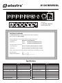
INTRODUCTION
A mixer amplifier with 6 selectable microphone or line inputs and phantom power, chime
function on CH1 and VOX priority on CH1 & CH2. Provision for the connection of 100V line or
low impedance loudspeakers. It also features a slave output and send/return for connection of
an effects unit. The amplifier can be powered from either 230Vac or a 24Vdc power source.
WARNING: THIS APPLIANCE MUST BE EARTHED
1. Channel ( 1-6 ) volume controls.
2. Bass and treble cut & boost controls
3. Master volume control
4. Power, Signal and Peak LED indicators
5. Power ON / OFF switch
6. Fused IEC mains input socket
7. Ground terminal
8. DC (24V) Input terminal
9. Loudspeaker output terminal block
10. Low impedance ( 8 & 16Ω ) loudspeaker 6.3mm jack sockets
11. Send/return effects 6.3mm sockets
12. Slave out RCA phono socket
13. Channel 1 Input. Features: Combination XLR / 6.3mm socket, RCA phono sockets,
terminal block for hard wiring of microphone & chime function, DIP switch for
selection of Mic/Line, VOX, chime & phantom power
14. Channel 2 Input. Features: Combination XLR / 6.3mm socket, RCA phono sockets,
DIP switch for selection of Mic / Line, VOX & phantom power
15. Channel 3-6 Inputs. Features: Combination XLR / 6.3mm socket, RCA phono sockets,
DIP switch for selection of Mic/Line & phantom power
LOUDSPEAKERS
All connections to the loudspeaker terminals should be made using suitable connectors
crimped or soldered to the speaker cables. Any other method can give rise to short circuits.
There is provision for 70V or 100V line and low impedance loudspeakers, but different types
must not be used on the same installation. In addition to the terminal block there are two
6.3mm jack sockets for connection of low impedance ( 8 and 16 ohms) loudspeakers. Low
impedance speakers can be connected in series, parallel or a series/parallel arrangement to
give the correct loading. Care should be taken with this set up in that the volume level is
carefully controlled, as it is possible to damage speakers by using too high a volume setting.
100 volt line should be connected to the COMMON and 100V terminals taking care that the
sum of the wattage of all the loudspeakers on the line does not exceed the total power
available from the amplifier. NOTE: It is good practice to allow a headroom of 10% when doing
your calculations. With 100 volt line installation all the speakers must be wired in parallel.
Please note that the loudspeaker terminals are fully floating with respect to chassis. In the
event of cross talk to other services or instability, then it may be beneficial if the COM terminal
is strapped to the earth binding post. Also note that a low impedance system requires heavy
duty cable feeding the loudspeakers to minimise losses. For a widespread installation it is far
better to use a 100 volt line system.
INPUT/OUTPUT CONNECTIONS
Each input has both balanced ( microphone/line ) combination XLR/6.3mm
and unbalanced (line only) RCA phono with DIP switches for selection of
microphone or line and phantom power.
Channel 1 has additional 3 pole screw terminal block for hard wiring a balanced microphone.
Chime activation is also provided by a DIP switch on CH 1, as well as a 2pole terminal block.
The chime is two tone (550Hz & 650Hz) and has the highest priority (Priority 1) and on
activation mutes all input signals. (Note: for full priority the VOX switch must be in the on
position) The chime is activated by external switch closing.
Microphone 1 overrides CH 2-6 inputs when the VOX switch is on (Priority 2 )
Microphone 2 overrides CH 3-6 inputs when the VOX switch is in the on position (Priority 3)
SLAVE out RCA phono socket is for connection to an additional booster amplifier.
ADDENDUM: The marking of the CHIME dip switch is incorrect. To activate the CHIME function
the switch must be in the 'OFF' position. Any further enquires please contact our technical
department.
The SEND and RETURN 6.3mm sockets are for connection of an effects unit. Loudspeaker
outputs are via a screw terminal block or 6.3mm sockets.
A 24 volt battery can be connected using suitable connectors crimped to the battery terminals.
Observe the correct polarity. NOTE : The power switch does not control the 24V supply to the
amplifier. The mains input is a fused IEC 3 pin socket.
SETTING UP
When all connections have been made, check that all the controls are at zero then plug the
mains lead provided into the amplifier and the 13 amp plug into a suitable 230 volt socket.
Depress the power switch on the front panel and the POWER LED illuminates.
Advance the MASTER control to 6 on its scale then using a local microphone in CH 1 input
slowly advance its volume control whilst speaking into the microphone. Observe the SIGNAL
indicator. As the control is advanced the indicator will start flashing in time with the peaks of
speech. This indicates that a signal is being passed to the loudspeakers. The control should be
set so that the peaks of sound keep the SIGNAL indicator almost continuously lit but the PEAK
LED only shows on rare occasions or not at all. Continuous illumination of the PEAK LED
indicates the amplifier is being overloaded.
If the MIC 1 control is at maximum without achieving the desired output then it will be
necessary to increase the MASTER setting a little and recommence the setting up procedure
until a satisfactory level of output is achieved.
It may be that before this setting can be achieved a howl – round (feed back) point is reached
where the system appears to become unstable, if this is the case then the nearest loudspeaker
and the microphone you are using are in each others sound fields and need to be repositioned.
If a 100 volt line system is being employed you can reset the nearer loudspeaker to a lower
wattage tap to minimise the howl-round (feed back).
The object of this setting up procedure is to balance the MASTER and MIC 1 controls so neither
are at a very low or a very high setting in relation to each other. When the initial set up is
completed try the other channels in the same way.
Most tape and CD players have additional level controls of their own which can be usefully
used to fine balance their volume levels with the LINE controls.
The bass and treble controls should initially be set to their minimum (anti-clockwise) positions
for setting up. Once this has been carried out then the tone controls can be set for personal
preference.
INTERFERENCE
Whilst this equipment complies in all respects with EMC legislation its use in an industrial
environment where there are many potential sources of interference means that steps may
need to be taken to minimise any problems. Always check that the amplifier has a good earth.
In the event of interference secure the services of a qualified electrician to carry out tests on
the socket to ensure a low resistance earth path exists.
DO NOT run microphone cables near mains, data, telephone or 100V line cables
DO NOT run 100V line cables near data, telephone or other low voltage cables
DO NOT position the amplifier very close to large transformers, TV monitors and computers
AVOID jointing the microphone cable, when this is unavoidable ensure
a good screened connector is used eg. XLR
ALWAYS use a balanced microphone terminating in a
balanced input on long microphone cable runs
ALWAYS use mains grade double insulated cable for 100V line cable runs
GB
WARNING: DO NOT CONNECT THE MAINS SUPPLY TO THE AMPLIFIER UNTIL ALL THE NECESSARY
INPUT AND OUTPUT CONNECTIONS HAVE BEEN MADE.
CIRCUIT DIAGRAMS ARE AVAILABLE ON REQUEST
AMPLIFIER MANUAL
CH-1
A126 MIXER AMPLIFIER 120W
CH-1
CH-2
CH-3
CH-4
CH-5 CH-6
CH-6
L
R
PHANTOMOFF
MICLINE
+VE
-VE
SCREEN
+2
-3
CH-5
L
R
PHANTOMOFF
MICLINE
+VE
-VE
SCREEN
+2
-3
CH-4
L
R
PHANTOMOFF
MICLINE
SCREEN
+VE
-VE
+2
-3
CH-3
L
R
PHANTOMOFF
MICLINE
+VE
-VE
+2
-3
CH-2
L
R
VOXOFF
PHANTOMOFF
MICLINE
SCREEN
+VE
-VE
+2
-3
L
R
VOXOFF
CHIMEOFF
PHANTOMOFF
MICLINE
SCREEN
+VE
-VE
+2
-3
CHIME + - GND
SLAVE OUTRETURNSEND
SPEAKER
8Ω 16Ω
OUTPUT
COM 8Ω 16Ω 70V 100V
SCREEN
SIG
-
+
SPEAKER
CONNECTIONS
24Vdc
+ -
Stock code: 952.997UK
110V / T4A
240V / T2A
110V~60Hz 240V~50Hz
CAUTION
DO NOT OPEN. NO USER
SERVICABLE PARTS INSIDE.
RISK OF ELECTRIC SHOCK
1 2 3 4
5
6
7
8 9
10 11 12
131415

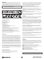
INTRODUCTION
Amplificateur/mixage avec 6 entrées micro ou ligne et alimentation fantôme. Carillon sur le
canal 1 et priorité VOX sur les canaux 1 et 2. Possibilité de connecter des haut-parleurs en ligne
100V ou basse impédance. Sortie esclave et send/return pour des effets externes.
L’amplificateur peut être alimenté par le secteur (230Vac) ou une source d’alimentation 24Vdc.
ATTENTION: CET APPAREIL DOIT ETRE RELIE A LA TERRE
1. Contrôles de volume canaux 1-6.
2. Réglages Cut & Boost des graves et aigus
3. Contrôle de volume général
4. Indicateurs de tension, signal et crête
5. Interrupteur Marche/Arrêt
6. Prise secteur IEC avec fusible
7. Borne de masse
8. Entrée d’alimentation 24Vdc
9. Bornier de sorties haut-parleurs
10. Prises jack 6,3mm pour HP basse impédance ( 8 & 16Ω )
11. Jacks 6,3 pour effets externes
12. Fiche RCA de sortie esclave
13. Entrée canal 1 Fiche combinée XLR/jack 6,3mm, fiches RCA, bornier pour la
connexion d’un micro & carillon. Commutateur DIP pour la sélection micro/ligne,
VOX, carillon & alimentation fantôme
14. Entrée canal 2 Fiche combinée XLR/jack 6,3mm, RCA, commutateur DIP
pour la sélection micro/ligne, VOX & alimentation fantôme
15. Entrées canaux 3-6 Fiche combinée XLR/jack 6,3mm, RCA, commutateur
DIP pour la sélection micro/ligne & alimentation fantôme
HAUT-PARLEURS
Effectuez toutes les connexions aux borniers de haut-parleurs avec des cosses à fourche
appropriées qui sont serties ou soudées aux câbles de haut-parleur. Toute autre méthode
risque de provoquer des courts-circuits. L’amplificateur accepte des enceintes en ligne 70V,
100V et basse impédance mais les deux types NE doivent PAS être utilisés ensemble dans la
même installation. En plus du bornier, deux fiches jack 6,3mm sont prévues pour la connexion
de HP basse impédance (8 et 16Ω). Des haut-parleurs basse impédance doivent être connectés
en série, en parallèle ou dans une configuration série/parallèle de façon à obtenir toujours la
bonne charge. Veillez dans cette configuration à ce que le volume soit strictement maîtrisé. Un
volume trop fort risque d’endommager les enceintes. Les HP 100V doivent être connectés sur le
bornier commun (COM) et ligne l00V en veillant à ce que la somme de la puissance de tous les
HP ne dépasse pas la puissance totale disponible de l’amplificateur. NOTE: Il est recommandé
de laisser une marge de manoeuvre de 10% lors des calculs. Dans une installation 100V, tous
les haut-parleurs doivent être connectés en parallèle.
Notez que tous les borniers de haut-parleurs sont isolés de la masse du châssis. En cas
d’interférences ou dans certaines circonstances, il peut être nécessaire de relier le bornier COM
au bornier de terre. N’oubliez pas qu’un système de basse impédance nécessite des câbles épais
qui alimentent les haut-parleurs afin de minimiser les pertes. Pour une installation vaste (p.ex.
dans une usine), il est vivement recommandé d’utiliser un système en ligne 100V.
CONNEXIONS D’ENTREE / SORTIE
Chaque entrée possède une entrée symétrique combinée XLR/jack 6,3mm (micro/ligne) et une
entrée asymétrique RCA (uniquement ligne avec des commutateurs DIP per-mettant de
sélectionner micro, ligne et alimentation fantôme.
Canal 1 possède par ailleurs un bornier à vis pour la connexion d’un microphone symétrique.
L’activation du carillon se fait par un commutateur DIP sur le canal 1 ainsi qu’un bornier à 2
positions. Le carillon est à 2 sons (550Hz & 650Hz) et possède la plus haute priorité (Priorité 1).
Lorsqu’il est activé, tous les signaux d’entrée sont coupés. Le carillon est activé par un
commutateur externe.
Microphone 1 est prioritaire sur les canaux 2-6 lorsque VOX est activé (Priorité 2 )
Microphone 2 est prioritaire sur les canaux 3-6 lorsque VOX est activé (Priorité 3)
Fiche RCA de sortie ESCLAVE vers un amplificateur supplémentaire.
Fiches jack 6,3mm SEND et RETURN pour la connexion à un effet externe. Les sorties HP se font
via un bornier à vis ou des jacks 6,3mm.
Branchez une batterie 24Vdc sur les borniers 24Vdc au moyen de cosses à fourches qui sont
serties sur les câbles de batterie. Respectez la bonne polarité. NOTE : L’interrupteur M/A ne
fonctionne pas avec une alimentation 24Vdc. L’entrée secteur est une fiche IEC à 3 broches.
MISE EN SERVICE
Lorsque toutes les connexions ont été effectuées, vérifiez que le contrôle MASTER se trouve sur
Zéro. Branchez le cordon secteur sur la fiche IEC au dos de l’amplificateur ainsi que dans une
prise secteur appropriée. Appuyez sur l’interrupteur ON/OFF et le voyant ‘POWER’ s’allumera.
Avancez le contrôle MASTER jusqu’à 6. Branchez un microphone sur l’entrée du canal 1 et
avancez son contrôle de volume tout en parlant dans le micro. Observez le voyant SIGNAL.
Lorsque le volume augmente, le voyant va commencer à clignoter, indiquant que le signal est
transmis aux HP. Le contrôle doit être réglé de telle manière que l’indicateur SIGNAL reste
pratiquement toujours allumé et l’indicateur PEAK ne s’allume que très peu ou pas du tout. Si
le voyant PEAK reste allumé en permanence, l’amplificateur est surchargé.
Si le contrôle MIC1 est au maximum sans atteindre la sortie souhaitée, augmentez légèrement
le réglage MASTER et recommencez jusqu’à l’obtention d’un résultat satisfaisant.
Avant d’arriver à ce réglage, il est possible qu’un effet larsen se produise et le système semble
devenir instable. Dans ce cas, le haut-parleur le plus proche et le microphone que vous utilisez
sont dans le même champ sonore et doivent être éloignés l’un de l’autre. Si vous utilisez un
système de ligne 100V, vous pouvez régler le HP le plus proche à un niveau de puissance plus
bas afin de minimiser l’effet larsen.
Le but de ce réglage est d’équilibrer les contrôles MASTER et MIC1 de façon à ce qu’aucun d’eux
ne soit à un réglage très élevé ou très bas par rapport à l’autre. Lorsque vous avez terminé la
mise en service initiale, essayez les autres canaux de la même façon.
La plupart des lecteurs CD et cassettes possèdent leurs propres contrôles de niveau qui
permettront un réglage fin de leur volume avec les contrôles LINE.
Les contrôles de graves et d’aigus doivent être réglés sur le minimum (anti-horaire) pour la
mise en service. Ensuite, ils peuvent être réglés en fonction du goût personnel.
INTERFERENCES
Bien que cet appareil soit en tous points conforme au règlement CEM, il peut être nécessaire
dans un environnement industriel en présence de nombreuses sources potentielles
d’interférences, de prendre certaines mesures afin de minimiser les difficultés éventuelles.
Vérifiez TOUJOURS la connexion à la terre. En cas d’interférences, un électricien qualifié doit
effectuer des tests sur la prise secteur pour s’assurer de la présence d’un chemin de basse
résistance.
NE PAS passer des câbles micro à proximité de câbles secteur,
informatiques, téléphone ou ligne 100V
NE PAS passer des câbles de ligne 100V à proximité de câbles
informatiques, téléphone ou autre basse tension
NE PAS placer l’amplificateur à proximité de grands transformateurs, écrans TV et ordinateurs
EVITEZ de joindre des câbles micro. Lorsque c’est inévitable
utilisez un connecteur blindé p.ex. un XLR
UTILISEZ TOUJOURS un micro symétrique avec une entrée
symétrique pour des grandes longueurs de câble
UTILISEZ TOUJOURS du câble à double isolation de qualité secteur pour les câbles 100V
AMPLIFIER MANUAL
FR
CH-1
A126 MIXER AMPLIFIER 120W
CH-1
CH-2
CH-3
CH-4
CH-5 CH-6
CH-6
L
R
PHANTOMOFF
MICLINE
+VE
-VE
SCREEN
+2
-3
CH-5
L
R
PHANTOMOFF
MICLINE
+VE
-VE
SCREEN
+2
-3
CH-4
L
R
PHANTOMOFF
MICLINE
SCREEN
+VE
-VE
+2
-3
CH-3
L
R
PHANTOMOFF
MICLINE
+VE
-VE
+2
-3
CH-2
L
R
VOXOFF
PHANTOMOFF
MICLINE
SCREEN
+VE
-VE
+2
-3
L
R
VOXOFF
CHIMEOFF
PHANTOMOFF
MICLINE
SCREEN
+VE
-VE
+2
-3
CHIME + - GND
SLAVE OUTRETURNSEND
SPEAKER
8Ω 16Ω
OUTPUT
COM 8Ω 16Ω 70V 100V
SCREEN
SIG
-
+
SPEAKER
CONNECTIONS
24Vdc
+ -
Stock code: 952.997UK
110V / T4A
240V / T2A
110V~60Hz 240V~50Hz
CAUTION
DO NOT OPEN. NO USER
SERVICABLE PARTS INSIDE.
RISK OF ELECTRIC SHOCK
1 2 3 4
5
6
7
8 9
10 11 12
131415
ATTENTION: NE PAS BRANCHER L’AMPLIFICATEUR SUR LE SECTEUR AVANT D’AVOIR

AMPLIFIER MANUAL
DE
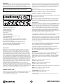
EINLEITUNG
Mischverstärker mit 6 wählbaren Mikrofon- oder Line-Eingängen, Gong auf Kanal 1 und VOX
Vorrangschaltung auf Kanal 1 & 2. Anschlussmöglichkeit für 100V Line oder niederohmige
Lautsprecher. Ausgang für einen Nebenverstärker, sowie Send/Return Schleife für
ein externes Effektgerät. Der Verstärker kann über 230V AC Netzstrom oder
eine 24V Batterie gespeist werden.
WARNUNG: DIESES GERÄT MUSS GEERDET
1. Lautstärkeregler für Kanäle 1 - 6
2. Cut und Boost Regler für Bässe und Höhen
3. Master Lautstärkeregler
4. Betrieb-, Signal- und Spitzenanzeiger
5. Ein/Aus Schalter
6. Gesicherte IEC Netzanschlussbuchse
7. Masseanschluss
8. 24V DC Stromeingang
9. Lautsprecherausgangsklemmen
10. 6,3mm Klinkenbuchsen für nieder-ohmige (8 & 16Ω) Lautsprecher
11. 6,3mm Buchsen für Send/Return
12. Cinch-Buchse für Nebenverstärker
13. Eingang Kanal 1 Kombinierte XLR/6,3mm Klinken-buchse, Cinch-Buchsen, Festan-schluss
für Mikrofon & Gong, DIP Schalter zur Wahl von Mikro/Line, VOX, Gong & Phantomspeisung
14. Eingang Kanal 2 Kombinierte XLR/6,3mm Klinken-buchse, Cinch-Buchsen,
DIP Schalter zur Wahl von Mikro/Line, VOX & Phantomspeisung
15. Eingänge Kanäle 3-6 Kombinierte XLR/6,3mm Klinken-buchse, Cinch-Buchsen,
DIP Schalter zur Wahl von Mikro/Line & Phantomspeisung
LAUTSPRECHER
Alle Anschlüsse an die Lautsprecherklemmen müssen über geeignete Flachsteckverbinder
erfolgen, die an die Lautsprecherkabel gekrimpt oder gelötet werden. Jede andere Methode
kann zu Kurzschlüssen führen. Es sind Anschlüsse sowohl für 70V oder 100V Line als auch
niederohmige Lautsprecher vorhanden. Diese beiden Typen dürfen jedoch NICHT zusammen in
derselben Anlage verwendet werden. Ausser der Klemmleiste sind noch zwei 6,3mm
Klinkenbuchsen für niederohmige (8 & 16Ω) Lautsprecher vorhanden. Niederohmige
Lautsprecher können parallel, in Serie oder in einer Serie/parallel Konfiguration angeschlossen
werden, um die richtige Belastung zu erzielen. Hierbei muss der Lautsprecherpegel sorgfältig
geprüft werden, da die Lautsprecher durch eine zu grosse Lautstärke beschädigt werden
können.100V Line Lautsprecher müssen an die gemeinsame (COM) und die 100V Line Klemme
angeschlossen werden, wobei die Leistungssumme aller Lautsprecher die gesamte Watt-zahl
des Verstärkers nicht übersteigen darf. Hinweis: Es ist ratsam, bei der Berechnung immer einen
Spielraum von 10% zu lassen. In einer 100V Line Anlage müssen alle Lautsprecher parallel
angeschlosen werden.
Alle Lautsprecherklemmen sind von der Masse isoliert. Falls Störungen auftreten, müssen
die “COM” Klemmen an eine Masseschraube angeschlossen werden. Beachten Sie bitte,
dass niederohmige Anlagen starke Lautsprecherkabel benötigen, um Verluste zu
verringern. Für weiträumige Anlagen (z.B. in einer Fabrik) ist es weitaus besser,
ein 100V Line System zu benutzen.
EIN- UND AUSGANGSVERBINDUNGEN
Jeder Eingang besitzt sowohl einen symmetrischen (Mikro/Line) kombinierten XLR/6,3mm,
als auch einen asymmetrischen (nur Line) Cinch-Eingang mit DIP Schaltern zur
Wahl von Mikrofon oder Line und Phantomspeisung.
Darüberhinaus verfügt Kanal 1 über eine zusätzliche 3-pol. Klemmleiste zum Festanschluss
eines symmetrischen Mikrofons. Die Gongaktivierung erfolgt über einen DIP-Schalter auf Kanal
1, sowie eine 2-pol. Klemmleiste. Der 2-tönige Gong (550Hz & 650Hz) besitzt den höchsten
Vorrang und unterbricht bei Aktivierung alle Eingangssignale. Der Gong wird über einen
externen Schliesskontakt aktiviert.
Mikrofon 1 hat Vorrang über Kanäle 2-6, wenn der VOX Schalter an ist (Stufe 2)
Mikrofon 2 hat Vorrang über Kanäle 3-6, wenn der VOX Schalter an ist (Stufe 3)
Die Cinch-Buchse ist der Ausgang zu einem Nebenverstärker (SLAVE).
Die 6,3mm SEND und RETURN Klinkenbuchsen sind zum Anschluss an einen Effektgenerator.
Die Lautsprecherausgänge erfolgen über eine Schraubklemmleiste oder 6,3mm
Klinkenbuchsen.
Eine 24V Batterie kann über geeignete Verbinder an die Batterieklemmen gekrimpt werden.
Beachten Sie die richtige Verpolung. HINWEIS: Der Ein/Aus Schalter regelt nicht die
24V Speisung. Der Netzeingang ist eine IEC Buchse mit Sicherung.
INBETRIEBNAHME
Wenn alle Anschlüsse durchgeführt worden sind, prüfen Sie, ob der MASTER Regler auf Null
steht. Stecken Sie das Netzkabel in die Buchse auf der Rückseite des Verstärkers und in eine
geerdete 230V AC Netzsteckdose. Drücken Sie auf den ON/OFF Schalter. Die Betriebsanzeige
leuchtet auf.
Schliessen Sie ein Mikrofon an den Eingang von Kanal 1 and und drehen Sie den MASTER
Regler auf 6. Erhöhen Sie allmählich die Lautstärke des Mikrofons, während Sie hinein
sprechen. Beobachten Sie die SIGNAL Anzeige. Bei steigender Lautstärke beginnt die Anzeige
zu blinken. Dies bedeutet, dass den Lautsprechern ein Signal zugeführt wird. Der Regler muss
so eingestellt werden, dass die Signalanzeige bei Klangspitzen fast ständig leuchtet, während
die PEAK Anzeige kaum bzw. gar nicht aufleuchten darf. Ein ständiges Leuchten der PEAK
Anzeige bedeutet, dass der Verstärker überlastet ist.
Wenn der MIC1 Regler auf die höchste Stufe eingestellt ist und der erwünschte Ausgangspegel
nicht erreicht ist, stellen Sie den MASTER Regler etwas höher und beginnen Sie von vorn bis
der gewünschte Pegel erreicht ist.
Bevor Sie diese Einstellung erreichen, kann Feedback auftreten. In diesem Fall ist der Abstand
zwischen dem Mikrofon und dem nächsten Lautsprecher zu gering. Wenn eine Anlage in 100V
Technik benutzt wird, kann der nächste Lautsprecher auf eine geringe Wattzahl eingestellt
werden, um das Feedback zu verringern.
Ziel dieses Einstellverfahrens ist es, die MASTER und MIC1 Regler so einzustellen, dass ihr
Verhältnis zueinander ausgewogen ist. Wenn die Grundeinstellung beendet ist, verfahren Sie
mit den anderen kanälen auf dieselbe Weise.
Die meisten Kassettenrekorder und CD Spieler besitzen zusätzliche Pegelregler, die benutzt
werden können, um ihre Lautstärkepegel an die LINE Regler anzupassen.
Die Bass- und Höhenregler müssen während des Einstellverfahrens auf die kleinste Einstellung
gereglet werden (gegen den Uhrzeigersinn). Danach können die Klangregler auf den
persönlichen Geschmack eingestellt werden.
STÖRUNGEN
Das Gerät entspricht den geltenden EMC Bestimmmungen. Der Einsatz in industrieller
Umgebung, wo zahlreiche Störquellen vorhanden sein können, kann die Ergreifung
bestimmter Massnahmen erfordern. Prüfen Sie IMMER den Erdanschluss des Verstärkers. Falls
Störungen auftreten sollten, ziehen Sie einen qualifizierten Elektriker zu Rate, um die nötigen
Tests an der Steckdose durchzuführen.
NIEMALS Mikrofonkabel in der Nähe von Netz-, Daten-, Telefon- oder 100V Line Kabeln
verlegen
NIEMALS 100V Line Kabel in der Nähe von Daten-, Telefon- oder Niederspannungskabeln
verlegen
NIEMALS den Verstärker in der Nähe von grossen Trafos, Fernseh- und Computerbildschirmen
aufstellen.
NIEMALS Mikrofonkabel miteinander verbinden. Wenn dies unvermeidbar ist, benutzen Sie
einen gut abgeschirmten Verbinder z.B. XLR.
IMMER bei langen Kabelführungen ein symmetrisches Mikrofon mit einem symmetrischen
Eingang benutzen.
IMMER doppelt isoliertes Kabel in Netzqualität für 100V Line Kabel verwenden.
CH-1
A126 MIXER AMPLIFIER 120W
CH-1
CH-2
CH-3
CH-4
CH-5 CH-6
CH-6
L
R
PHANTOMOFF
MICLINE
+VE
-VE
SCREEN
+2
-3
CH-5
L
R
PHANTOMOFF
MICLINE
+VE
-VE
SCREEN
+2
-3
CH-4
L
R
PHANTOMOFF
MICLINE
SCREEN
+VE
-VE
+2
-3
CH-3
L
R
PHANTOMOFF
MICLINE
+VE
-VE
+2
-3
CH-2
L
R
VOXOFF
PHANTOMOFF
MICLINE
SCREEN
+VE
-VE
+2
-3
L
R
VOXOFF
CHIMEOFF
PHANTOMOFF
MICLINE
SCREEN
+VE
-VE
+2
-3
CHIME + - GND
SLAVE OUTRETURNSEND
SPEAKER
8Ω 16Ω
OUTPUT
COM 8Ω 16Ω 70V 100V
SCREEN
SIG
-
+
SPEAKER
CONNECTIONS
24Vdc
+ -
Stock code: 952.997UK
110V / T4A
240V / T2A
110V~60Hz 240V~50Hz
CAUTION
DO NOT OPEN. NO USER
SERVICABLE PARTS INSIDE.
RISK OF ELECTRIC SHOCK
1 2 3 4
5
6
7
8 9
10 11 12
131415
WARNUNG: ERST ALLE EIN- UND AUSGÄNGE ANSCHLIESSEN,
BEVOR SIE DAS GERÄT ANS NETZ ANSCHLIESSEN
-
 1
1
-
 2
2
-
 3
3
-
 4
4


Adastra A126 Benutzerhandbuch
- Kategorie
- Audioverstärker
- Typ
- Benutzerhandbuch
in anderen Sprachen
- English: Adastra A126 User manual
- français: Adastra A126 Manuel utilisateur
Verwandte Artikel
Andere Dokumente
-
HQ HA30W Spezifikation
-
Eagle P650A Installation And Operating Instructions Manual
-
-
Ultrak KAB 2060M Benutzerhandbuch
-
 Maintronic AV32 Amplifier Remote Benutzerhandbuch
-
RCS VLA-601A-602A Bedienungsanleitung
-
-
Zeck Audio VECTOR T2A Bedienungsanleitung
-
-
