Monacor PA-1500D Benutzerhandbuch
- Kategorie
- Komponenten von Sicherheitsgeräten
- Typ
- Benutzerhandbuch

ELECTRONICS FOR SPECIALISTS ELECTRONICS FOR SPECIALISTS ELECTRONICS FOR SPECIALISTS ELECTRONICS FOR SPECIALISTS
BEDIENUNGSANLEITUNG
INSTRUCTION MANUAL
MODE D’EMPLOI
ISTRUZIONI PER L’USO
VEILIGHEIDSVOORSCHRIFTEN
CONSEJOS DE SEGURIDAD
ŚRODKI BEZPIECZEŃSTWA
SIKKERHEDSOPLYSNINGER
SÄKERHETSFÖRESKRIFTER
TURVALLISUUDESTA
ELA-Leistungsverstärker
PA Power Amplifier
PA-1500D
Bestell-Nr. • Order No. 17.7080


ELECTRONICS FOR SPECIALISTS ELECTRONICS FOR SPECIALISTS ELECTRONICS FOR SPECIALISTS ELECTRONICS FOR SPECIALISTS
3
Deutsch ...........Seite 4
English ............Page 7
Français ...........Page 10
Italiano............Pagina 13
Nederlands ........Pagina 16
Español ...........Página 16
Polski .............Strona 17
Dansk .............Sida 17
Svenska ...........Sidan 18
Suomi.............Sivulta 18

4
Deutsch
English
English Page
Français
Français Page
Italiano
Italiano Pagina
Español
Español Página
Nederlands
Nederlands Pagina
Polski
Polski Strona
CONTACT
MAX 1A
0dBu (0.775 V)
30 kΩ BAL
OFF: FAULT
ON: NORMAL
MAX 0.1A
GND
OUT PRI
CTL
24V
PA-6FD
G
0 100 10
0dBu (0.775 V)
30 kΩ BAL
G
PA-6FD
FAULT DETECTION MODULE
GND
200 Hz
SLEEP
COM
20
COM
100
V
BALANCED
OUTPUTS
24 V /35.5 A
FUSE FUSE RATING
500 WRMS
F
U
S
E
40 123
ON
230 V~/50 Hz
PA -15 0 0 D
MONO CLASS D PA MIXING
AMPLIFIER
MONACOR INTERNATIONAL • ZUM FALSCH 36 • 28307 BREMEN • GERMANY
230
V~
/
50
Hz
/
1015
VA
T6.3AL
24V /35.5 A
LEVELLEVEL
FD/PRIORITY
CONTROL
PRIORITY
INPUT
PRI
RELAY
PGM
INPUT
POWER
REMOTE
T40AL
PA-1500D
OCP RESET
FAULT
PROTECT
CLIP
SIGNAL
ON
STAND BY
PRIORITYSLEEP
POWER
4
5 6 7 8 9
10 11 13 14 15 16 18
2
19
3
1
12 17
ELA-Leistungsverstärker
Diese Anleitung richtet sich an Installateure
mit Fachkenntnissen in der 100-V-Beschal-
lungstechnik. Bitte lesen Sie die Anleitung vor
der Installation gründlich durch und heben Sie
sie für ein späteres Nachlesen auf.
1 Verwendungsmöglichkeiten
Der Verstärker PA-1500D mit einer Nenn-
ausgangsleistung von 500 W ist speziell für
den Einsatz in ELA-Anlagen konzipiert. Für
Hintergrundmusik und für normale Durch-
sagen ist ein Line-Pegel-Eingang vorhanden.
Für Notfalldurchsagen oder andere wichtige
Durchsagen ist ein zweiter Line-Pegel-Eingang
vorhanden. Mit einem separaten Schalter
oder mit einem externen Relais lässt sich auf
den zweiten Eingang umschalten.
2 Übersicht
Hinweis: Alle grünen Anschlussleisten lassen sich zur
besseren Handhabung von ihren Steckverbindungen
abziehen.
1 Anzeige-LEDs
FAULT
leuchtet, wenn ein Fehler im Verstärker
aufgetreten ist
PROTECT
leuchtet, wenn der Verstärker überhitzt
oder ein Fehler im Verstärker aufgetre-
ten ist
CLIP
leuchtet, wenn der Verstärker übersteu-
ert wird [Lautstärkeregler LEVEL (12)
oder (17) zurückdrehen]
SIGNAL
leuchtet ab einen bestimmten Signal-
pegel auf
ON Betriebsanzeige
STAND BY
leuchtet, wenn der Verstärker mit dem
230-V-Stromnetz verbunden ist, mit
dem Netzschalter (3) ausgeschaltet ist
PRIORITY
leuchtet, wenn der Verstärker über den
Anschluss PRI CTL (16) auf den Eingang
PRIORITY INPUT (18) umgeschaltet ist
SLEEP
leuchtet, wenn kein Eingangssignal vor-
handen ist und der Verstärker in den
Stromspar-Modus umgeschaltet hat
2
Rückstelltaste (versenkt) für die Schutz-
schaltung
3 Ein-Aus-Schalter POWER
4 Masseanschluss
5
Netzbuchse zum Anschluss an eine Steck-
dose (230 V/ 50 Hz) über das beiliegende
Netzkabel
6 Halterung für die Netzsicherung;
eine durchgebrannte Sicherung nur durch
eine gleichen Typs ersetzen
7
Anschluss POWER REMOTE für einen
externen Schalter zum ferngesteuerten
Ein- und Ausschalten
Hinweis: Zur Fernsteuerung darf der Verstärker
nicht mit dem Schalter POWER (3) eingeschaltet
sein.
8
Anschluss 24 V ⎓ für eine 24-V-Notstrom-
einheit
9 Sicherung für die 24-V-Versorgung;
eine durchgebrannte Sicherung nur durch
eine gleichen Typs ersetzen
10 Lautsprecheranschluss BALANCED
OUTPUTS
11
Anschluss für das interne Relais: Das Relais
schaltet, wenn der Verstärker über den
Anschluss PRI CTL (16) auf den Eingang
PRIORITY INPUT (18) umgeschaltet wird
12
Lautstärkeregler LEVEL für den Eingang
PGM INPUT (13)
13
symmetrischer Line-Pegel-Eingang PGM
INPUT für normale Durchsagen und Hin-
tergrundmusik
14 DIP-Schalter
Nr. 1 zum Ein- und Ausschalten der Strom-
spar-Automatik (Kap. 6, Schritt 6)
Nr. 2 zum Ein- und Ausschalten des
200-Hz-Hochpasses (senkt zur besse-
ren Sprachverständlichkeit die Bässe ab)
N r. 3 für Modul PA-6FD (Zubehör, Kap. 4)
untere Position ON: ohne PA-6FD
obere Position: mit PA-6FD
15
Kontroll-LED: Leuchtet, wenn der Verstär-
ker ordnungsgemäß arbeitet
16 Anschluss +24V / GND für die 24-V-Hilfs-
spannung, belastbar mit 0,1 A
Anschluss PRI CTL / GND für einen Vor-
rangschalter: Bei geschlossenem Schal
-
ter schaltet der Verstärker vom Eingang
PGMINPUT (13) auf den Eingang PRIO-
RITY INPUT(18) um.
17
Lautstärkeregler LEVEL für den Eingang
PRIORITY INPUT (18)
18
symmetrischer Line-Pegel-Eingang PRI-
ORITY INPUT für wichtige Durchsagen –
siehe auch Positionen 16 und 17
19
Abdeckblech, wird zum Einsetzen des Feh-
lerüberwachungsmoduls PA-6FD entfernt
3 Hinweise für den
sicherenGebrauch
Das Gerät entspricht allen relevanten Richtli-
nien der EU und trägt deshalb das -Zeichen.
WARNUNG Das Gerät wird mit lebensge-
fährlicher Netzspannung ver-
sorgt. Nehmen Sie deshalb
niemals selbst Eingriffe am
Gerät vor und stecken Sie nichts durch die
Lüftungsöffnungen! Es besteht die Gefahr
eines elektrischen Schlages.
Im Betrieb liegt am Lautsprecheranschluss
BALANCED
OUTPUTS
(10) berührungsgefährliche Spannung
bis 100 V an. Alle Anschlüsse nur bei aus-
geschaltetem Verstärker vornehmen oder
verändern.
•
Das Gerät ist nur zur Verwendung im In-
nenbereich geeignet. Schützen Sie es vor
Tropf- und Spritzwasser sowie hoher Luft-
feuchtigkeit. Der zulässige Einsatztempe-
raturbereich beträgt 0 – 40 °C.
•
Stellen Sie keine mit Flüssigkeit gefüllten
Gefäße, z. B. Trinkgläser, auf das Gerät.
•
Die in dem Gerät entstehende Wärme muss
durch Luftzirkulation abgegeben werden.
Decken Sie darum die Lüftungsöffnungen
des Gehäuses nicht ab.
•
Trennen Sie das Gerät sofort von der Strom-
versorgung, wenn:
1.
sichtbare Schäden am Gerät oder am
Stromversorgungskabel vorhanden sind,
2.
nach einem Sturz oder Ähnlichem der
Verdacht auf einen Defekt besteht,
3. Funktionsstörungen auftreten.
Geben Sie das Gerät in jedem Fall zur
Reparatur in eine Fachwerkstatt.
•
Ziehen Sie den Netzstecker nie am Kabel
aus der Steckdose, fassen Sie immer am
Stecker an.
•
Verwenden Sie zur Reinigung nur ein tro-
ckenes, weiches Tuch, niemals Chemikalien
oder Wasser.
•
Wird das Gerät zweckentfremdet, nicht
richtig angeschlossen, falsch bedient oder
nicht fachgerecht repariert, kann keine
Garantie für das Gerät und keine Haftung
für daraus resultierende Sach- oder Perso-
nenschäden übernommen werden.
Soll das Gerät endgültig aus dem
Betrieb genommen werden, über-
geben Sie es zur umweltgerechten
Entsorgung einem örtlichen Recy-
clingbetrieb.
Deutsch
Deutsch Seite

5
Deutsch
CONTACT
MAX 1A
0dBu (0.775 V)
30 kΩ BAL
OFF: FAULT
ON: NORMAL
MAX 0.1A
GND
OUT PRI
CTL
24V
PA-6FD
G
0 100 10
0dBu (0.775 V)
30 kΩ BAL
G
PA-6FD
FAULT DETECTION MODULE
GND
200 Hz
SLEEP
COM
20
COM
100
V
BALANCED
OUTPUTS
24 V /35.5 A
FUSE FUSE RATING
500 WRMS
F
U
S
E
40 123
ON
230 V~/50 Hz
PA -15 0 0 D
MONO CLASS D PA MIXING
AMPLIFIER
MONACOR INTERNATIONAL • ZUM FALSCH 36 • 28307 BREMEN • GERMANY
230
V~
/
50
Hz
/
1015
VA
T6.3AL
24V /35.5 A
LEVELLEVEL
FD/PRIORITY
CONTROL
PRIORITY
INPUT
PRI
RELAY
PGM
INPUT
POWER
REMOTE
T40AL
PA-1500D
OCP RESET
FAULT
PROTECT
CLIP
SIGNAL
ON
STAND BY
PRIORITYSLEEP
POWER
4
5 6 7 8 9
10 11 13 14 15 16 18
2
19
3
1
12 17
4 Fehlerüberwachungsmodul
PA-6FD
4.1 Funktion
Das als Zubehör lieferbare Fehlerüberwa-
chungsmodul PA-6FD ist speziell für die-
sen Verstärker konzipiert. Es erzeugt einen
20-kHz-Sinuston, der auf die Endstufe gege-
ben wird. Liegt dieser Testton aufgrund eines
Defekts im Verstärker nicht am Lautsprecher-
anschluss (10) an, leuchten die Anzeigen
FAULT und PROTECT (1) auf. Außerdem er-
lischt die grüne LED (15) auf der Verstärker-
rückseite. Über ein Relais lässt sich zusätzlich
ein Signalgeber aktivieren.
4.2 Einbau und Anschluss
WARNUNG
Der Einbau des Moduls darf
nur durch Fachpersonal er-
folgen. Vor dem Öffnen des
Verstärkers den Netzstecker
aus der Steckdose ziehen, an-
derenfalls besteht die Gefahr
eines elektrischen Schlages!
Falls eine Notstromeinheit angeschlossen ist,
diese von den Anschlüssen 24 V ⎓ (8) tren-
nen, damit der Verstärker auf jeden Fall außer
Betrieb ist.
SW 1
ON OFF
CN601
Fault Detector
COM HOT
Line In
Sensitivity
OSC Level
PA-6FD
PA-6FD
min. max.
Sense
a b dc e
1)
Den Gehäusedeckel des Verstärkers ab-
schrauben und das Abdeckblech (19) ent-
fernen. Die 4-polige Leitung, die am Ab-
deckblech befestigt ist, vom Blech lösen.
2) Die Steckbrücke SW 1 auf dem Modul in
die Position ON stecken.
3)
Das Modul an der Stelle des Abdeckblechs
von außen einsetzen und festschrauben.
4)
Die 4-polige Leitung, die am Abdeckblech
befestigt war, in die Buchse CN 601 des
Moduls stecken. Dabei muss der obere Pin
der Buchse frei bleiben, siehe Abbildung
des Moduls.
5) Die Anschlussleiste BALANCED
OUTPUTS (10) des Verstär-
kers wie folgt mit der Anschlussleiste „Line
In“ (b) des Moduls verbinden:
COM
100
V
BALANCED
OUTPUTS
COM HOT
PA-6FD
PA-1500D
Line In – (b)(a) –
6)
Den DIP-Schalter Nr. 3 (14) in die obere
Position OFF (= FAULT) stellen.
7) Wird von dem Modul ein Fehler erkannt,
leuchten die LEDs FAULT und PROTECT (1)
auf und der Relaiskontakt
COM
100
V
BALANCED
OUTPUTS
COM HOT
PA-6FD
PA-1500D
Line In – (b)(a) –
(a) schließt.
An den Kontakt lässt sich zur Alarmierung
ein Signalgeber anschließen. Die Belast-
barkeit des Relaiskontakts beträgt 1 A bei
max. ~ 120 V oder max. ⎓ 24 V.
Hinweis: Der Relaiskontakt schließt auch, wenn
der Verstärker ausgeschaltet wird.
4.3 Kalibrierung
Es wird ein Oszilloskop oder ein Voltmeter
benötigt, das Wechselspannungen bis min-
destens 20 kHz messen kann.
1) An den Verstärkereingängen PGM INPUT
(13) und PRIORITY INPUT (18) darf kein
Signal anliegen. Gegebenenfalls die An-
schlussleisten abziehen.
2) Den Verstärker einschalten und am Laut-
sprecheranschluss BALANCED
OUTPUTS den 20-kHz- Test-
ton messen. Mit dem Trimmregler OSC
Level (d) den Pegel auf 2 V (5,6 Vss) ein-
stellen.
3)
Den Trimmregler Sensitivity (e) soweit auf-
drehen, dass die LED Sense (c) aufleuchtet.
Den Regler dann noch zwei Skalenstriche
weiterdrehen. Die LED kann im Betrieb
flackern; dieses ist kein Fehler.
4)
Den Verstärker ausschalten, die Anschluss-
leisten wieder auf die Eingänge PGM INPUT
und PRIORITY INPUT stecken. Der Verstärker
kann jetzt in Betrieb genommen werden.
5 Verstärker aufstellen und
anschließen
Der Verstärker ist für den Einschub in ein
Rack (482 mm /19”) vorgesehen, kann aber
auch als Tischgerät verwendet werden. In
jedem Fall muss Luft ungehindert durch alle
Lüftungsöffnungen strömen können, damit
eine ausreichende Kühlung der Endstufen
gewährleistet ist.
5.1 Rackeinbau
Für die Rackmontage werden 2 HE (2 Höhen-
einheiten = 89 mm) benötigt. Damit das Rack
nicht kopflastig wird, muss der Verstärker im
unteren Bereich des Racks eingeschoben wer-
den. Für eine sichere Befestigung reicht die
Frontplatte allein nicht aus. Zusätzlich müs-
sen Seitenschienen oder eine Bodenplatte das
Gerät halten.
Die vom Verstärker erwärmte Luft muss
aus dem Rack austreten können. Anderenfalls
kommt es im Rack zu einem Hitzestau, wo-
durch nicht nur der Verstärker, sondern auch
andere Geräte im Rack beschädigt werden
können. Bei unzureichendem Wärmeabfluss
in das Rack eine Lüftereinheit (z. B. DPVEN-
04) einsetzen.
5.2 Verstärker anschließen
Alle Anschlüsse dürfen nur durch Fachper
-
sonal und bei ausgeschaltetem Verstärker
vorgenommen werden!
Hinweis: Alle grünen Anschlussleisten lassen sich zu
besseren Handhabung von ihren Steckverbindungen
abziehen.
5.2.1 Lautsprecher
Die ELA-Lautsprecher an die Anschlussleiste
BALANCED
OUTPUTS (10) anschließen. Dabei auf die gleiche
Polung aller Lautsprecher achten (z. B. COM =
Minus). Die Gesamtbelastung von 500 W darf
durch die Lautsprecher nicht überschritten
werden, sonst spricht die Schutzschaltung an
und schaltet den Verstärker stumm.
5.2.2 Line-Pegel-Eingänge
Für Durchsagen und Musikwiedergabe wird
ein ELA-Vorverstärker (z. B. PA-1414MX) oder
ein Zonen-Mischer (z. B. MPX-4PA, PMX-52PA)
benötigt, an den Mikrofone und Audiogeräte
(z. B. CD-Spieler, Radiogerät) angeschlossen
werden können. Den Ausgang dieses Geräts
mit dem Eingang PGM INPUT (13) verbinden.
Für Notfalldurchsagen oder andere wich-
tige Durchsagen ist der PA-1500D mit dem
Eingang PRIORITY INPUT (18) ausgestattet.

6
Deutsch
CONTACT
MAX 1A
0dBu (0.775 V)
30 kΩ BAL
OFF: FAULT
ON: NORMAL
MAX 0.1A
GND
OUT PRI
CTL
24V
PA-6FD
G
0 100 10
0dBu (0.775 V)
30 kΩ BAL
G
PA-6FD
FAULT DETECTION MODULE
GND
200 Hz
SLEEP
COM
20
COM
100
V
BALANCED
OUTPUTS
24 V /35.5 A
FUSE FUSE RATING
500 WRMS
F
U
S
E
40 123
ON
230 V~/50 Hz
PA -15 0 0 D
MONO CLASS D PA MIXING
AMPLIFIER
MONACOR INTERNATIONAL • ZUM FALSCH 36 • 28307 BREMEN • GERMANY
230
V~
/
50
Hz
/
1015
VA
T6.3AL
24V /35.5 A
LEVELLEVEL
FD/PRIORITY
CONTROL
PRIORITY
INPUT
PRI
RELAY
PGM
INPUT
POWER
REMOTE
T40AL
PA-1500D
OCP RESET
FAULT
PROTECT
CLIP
SIGNAL
ON
STAND BY
PRIORITYSLEEP
POWER
4
5 6 7 8 9
10 11 13 14 15 16 18
2
19
3
1
12 17
Sobald ein mit den Klemmen PRI CTL /GND
(16) verbundener Vorrangschalter oder ein
verbundenes Relais geschlossen wird, schaltet
der Verstärker vom Eingang PGM INPUT auf
den Eingang PRIORITY INPUT um und es ist
nur die Notfalldurchsage zu hören. Die Laut-
stärke für Notfalldurchsagen wird separat mit
dem Regler LEVEL (17) eingestellt.
5.2.3 Vorrangrelais und 24-V-Hilfsspannung
Wenn an den Klemmen PRI CTL /GND (16) ein
Relais oder ein Vorrangschalter angeschlos-
sen ist und dieses / dieser geschlossen wird,
schaltet auch das interne Vorrangrelais um.
Über dessen Anschlüsse PRI RELAY (11) lassen
sich weitere Vorgänge steuern. Zum Beispiel
können ELA-Lautstärkeeinsteller mit Pflicht-
empfangsrelais so auf maximale Lautstärke
geschaltet werden.
Wird zum Schalten der Pflichtempfangs-
relais eine 24-V-Spannung benötigt, kann z. B.
die Spannung von der Klemme +24 V (16)
über die Relaiskontakte geleitet werden.
CONTACT
MAX 1A
0dBu (0.775 V)
30 kΩ BAL
OFF: FAULT
ON: NORMAL
MAX 0.1A
GND
OUT PRI
CTL
24V
PA-6FD
G
0 100 10
0dBu (0.775 V)
30 kΩ BAL
G
200 Hz
SLEEP
123
ON
LEVELLEVEL
FD/PRIORITY
CONTROL
PRIORITY
INPUT
PRI
RELAY
PGM
INPUT
Vorrangschalter
Pflichtempfangsrelais
Die 24-V-Spannung ist mit 100 mA belastbar
und lässt sich auch für andere Anwendungen
nutzen.
5.2.4 Ferngesteuertes Ein- und Ausschalten
Der Verstärker lässt sich mit einem an der An-
schlussleiste POWER REMOTE (7) verbunde-
nen Schalter ferngesteuert ein- und ausschal-
ten. Dazu darf der Verstärker nicht mit dem
Netzschalter POWER (3) eingeschaltet sein.
5.2.5 Strom- und Notstromversorgung
1)
Zum Schluss das beiliegende Netzkabel
zuerst in die Netzbuchse (5) und dann in
eine Steckdose (230 V/ 50 Hz) stecken.
2) Soll der Verstärker bei einem eventuellen
Netzausfall weiterarbeiten, an die Schraub-
klemmen 24 V ⎓ (8) eine 24-V-Notstrom-
einheit (z. B. PA-24ESP von MONACOR)
anschließen. Bei einer Kabellänge bis zu
4 m ist ein Kabelquerschnitt von mindes-
tens 5 mm2 erforderlich.
6 Inbetriebnahme
Ist der Verstärker ausgeschaltet und liegt
die Netzspannung an, leuchtet die Anzeige
STANDBY (1).
1) Um Einschaltgeräusche zu vermeiden, zu-
erst alle anderen Geräte der ELA-Anlage
einschalten.
2) Um beim ersten Einschalten eine zu hohe
Anfangslautstärke zu vermeiden, die zwei
Regler LEVEL (12, 17) auf null stellen.
Dann den Verstärker mit dem Schalter
POWER(3) oder mit einem an den Klem-
men POWER REMOTE (7) angeschlossenen
Schalter einschalten. Die Betriebsanzeige
ON leuchtet. Während des Einschaltvor-
gangs ist der Verstärker stummgeschaltet
und die Anzeige PROTECT leuchtet zu-
sätzlich.
3)
Die gewünschte Lautstärke der Signal-
quelle am Anschluss PGM INPUT (13)
mit dem Regler LEVEL (12) links daneben
einstellen. Die Anzeige SIGNAL leuchtet
ab einen bestimmten Signalpegel auf. Bei
Übersteuerung leuchtet die rote Anzeige
CLIP auf. Dann die Lautstärke mit dem
Regler reduzieren.
4)
Die Lautstärke für wichtige Durchsagen,
die über den Eingang PRIORITY INPUT (18)
auf den Verstärker gegeben werden, mit
dem Regler LEVEL (17) einstellen. Dazu
muss der Vorrangschalter (oder das Relais)
an den Klemmen PRI CTL /GND (16) ge-
schlossen werden. Die Anzeige PRIORITY
leuchtet dann auf.
5)
Für eine bessere Sprachverständlichkeit
lässt sich mit dem DIP-Schalter Nr. 2 (14)
ein Hochpassfilter (200 Hz) einschalten
( Position ON). Tieffrequente Störgeräusche
werden damit unterdrückt.
6)
Um den Stromverbrauch zu reduzieren,
sind ein Schaltnetzteil und eine Klasse-D-
Endstufe verwendet worden. Um zusätz-
lich Energie zu sparen, kann der Verstärker
in den Schlafmodus schalten, wenn 10 s
lang kein Eingangssignal anliegt. Zur Kon-
trolle leuchtet dann die Anzeige SLEEP (1).
Sobald ein Signal wieder am Eingang vor-
handen ist, schaltet der Verstärker in den
Normalbetrieb zurück. Zum Einschalten
der Schlafautomatik den DIP-Schalter Nr.1
(14) in die untere Position auf ON stellen.
7 Schutzschaltung
Der Verstärker ist mit einer Schutzschaltung
gegen Überhitzung, Überlastung und Kurz-
schluss am Lautsprecherausgang ausge-
stattet. Bei einer Überhitzung leuchtet die
Anzeige PROTECT (1) auf. Bei Überlastung,
einem Kurzschluss oder einem anderen Fehler
leuchtet zusätzlich die Anzeige FAULT auf. In
jedem Fall wird der Verstärker stummgeschal-
tet. Leuchtet eine dieser Anzeigen auf, den
Verstärker ausschalten und den Fehler durch
Fachpersonal beheben lassen. Sollte sich die
Schutzschaltung nach der Fehlerbeseitigung
nicht selbsttätig zurücksetzen, die versenkte
Taste OCP RESET (2) dazu mit einem dünnen,
nichtleitenden Gegenstand betätigen.
Ist das Fehlerüberwachungsmodul PA-
6FD (Kap. 4) nicht eingesetzt, den DIP-Schal-
ter Nr. 3 (14) in die untere Position auf ON
(= normal) stellen, sonst spricht die Schutz-
schaltung an.
8 Technische Daten
Ausgangsleistung
Nennleistung: . . . . . . 500 W
Musikleistung: . . . . . 650 W
Klirrfaktor: . . . . . . . . . < 0,5 %
Ausgangsspannung
bei Nennleistung: . . . . 100 V
Lastimpedanz: . . . . . . . ≥ 20 Ω
Audio-Eingänge
Empfindlichkeit: . . . . 775 mV
Impedanz: . . . . . . . . 30 kΩ
Anschluss: . . . . . . . . symmetrisch
Frequenzbereich: . . . . 50 Hz – 18 kHz,
±3 dB
Störabstand: . . . . . . . . > 100 dB,
A-bewertet
Hochpassfilter: . . . . . . 200 Hz, 6 dB / Oktave
Stromversorgung
Netzspannung: . . . . . 230 V/ 50 Hz
Leistungsaufnahme: . 1015 VA max.,
im Schlafmodus 4 W
Notstromversorgung: ⎓ 24 V, 35,5 A,
im Schlafmodus
480 mA
Einsatztemperatur: . . . 0 – 40 °C
Abmessungen
(B × H × T): . . . . . . . . . 482 × 88 × 365 mm
2 HE
Gewicht: . . . . . . . . . . . 9 kg
Anschlüsse: . . . . . . . . . Schraubklemmen
(außer für 230 V)
Änderungen vorbehalten.
Diese Bedienungsanleitung ist urheberrechtlich für MONACOR
®
INTERNATIONAL GmbH & Co. KG
geschützt. Eine Reproduktion für eigene kommerzielle Zwecke – auch auszugsweise – ist untersagt.

7
English
Italiano
Italiano Pagina
Español
Español Página
Nederlands
Nederlands Pagina
Polski
Polski Strona
CONTACT
MAX 1A
0dBu (0.775 V)
30 kΩ BAL
OFF: FAULT
ON: NORMAL
MAX 0.1A
GND
OUT PRI
CTL
24V
PA-6FD
G
0 100 10
0dBu (0.775 V)
30 kΩ BAL
G
PA-6FD
FAULT DETECTION MODULE
GND
200 Hz
SLEEP
COM
20
COM
100
V
BALANCED
OUTPUTS
24 V /35.5 A
FUSE FUSE RATING
500 WRMS
F
U
S
E
40 123
ON
230 V~/50 Hz
PA -15 0 0 D
MONO CLASS D PA MIXING
AMPLIFIER
MONACOR INTERNATIONAL • ZUM FALSCH 36 • 28307 BREMEN • GERMANY
230
V~
/
50
Hz
/
1015
VA
T6.3AL
24V /35.5 A
LEVELLEVEL
FD/PRIORITY
CONTROL
PRIORITY
INPUT
PRI
RELAY
PGM
INPUT
POWER
REMOTE
T40AL
PA-1500D
OCP RESET
FAULT
PROTECT
CLIP
SIGNAL
ON
STAND BY
PRIORITYSLEEP
POWER
4
5 6 7 8 9
10 11 13 14 15 16 18
2
19
3
1
12 17
English
English Page
PA Power Amplifier
These instructions are intended for installers
with specific knowledge in sound reproduc-
tion using 100 V technology. Please read the
instructions carefully prior to installation and
keep them for later reference.
1 Applications
The amplifier PA-1500D with a rated output
power of 500 W is specially designed for
applications in PA systems. It is equipped with
a line level input for background music and
standard announcements. A second line level
input is provided for emergency announce-
ments or other important announcements.
A separate switch or an external relay can be
used for switching over to the second input.
2 Overview
Note: To make handling easier, all green terminal
strips can be disconnected from their plug-in con-
nections.
1 LED indicators
FAULT
will light up to indicate a fault in the
amplifier
PROTECT
will light up to indicate overheating or
a fault in the amplifier
CLIP
will light up to indicate overload
[turn back the volume control LEVEL (12)
or (17)]
SIGNAL
will light up when a specific signal level
is reached
ON power LED
STAND BY
will light up when the amplifier is
connected to the 230 V mains and is
switched off with the power switch (3)
PRIORITY
will light up when the connection
PRI CTL (16) is used to switch over
the amplifier to the input PRIORITY
INPUT(18)
SLEEP
will light up when there is no input
signal and the amplifier is in the sleep
mode to save power
2
Reset button (recessed) for the protective
circuit
3 POWER switch
4 Ground connection
5
Mains jack for connection to a mains
socket (230 V/ 50 Hz) via the mains cable
provided
6 Support for the mains fuse;
always replace a blown fuse by one of
the same type
7 Connection POWER REMOTE for an ex-
ternal switch used for remote-controlled
activation/deactivation
Note: When using the remote control feature,
make sure that the amplifier has not been
switched on with the POWER switch (3).
8 Connection 24 V ⎓ for a 24 V emergency
power supply unit
9 Fuse for the 24 V power supply;
always replace a blown fuse by one of
the same type
10 Speaker terminals
BALANCED
OUTPUTS
11
Connection for the internal relay: The
relay will respond when the connection
PRI CTL (16) is used to switch the amplifier
to the input PRIORITY INPUT (18).
12 Volume control LEVEL for the input PGM
INPUT (13)
13
Balanced line level input PGM INPUT
for standard announcements and back-
ground music
14 DIP switches
No. 1 to activate / deactivate the automatic
sleep mode to save power (chapter6,
step6)
No. 2 to activate / deactivate the 200 Hz
high-pass filter (for attenuating the low
frequencies in order to improve speech
intelligibility)
No. 3 for module PA-6FD (accessory,
chapter 4)
lower position ON: without PA-6FD
upper position: with PA-6FD
15
LED indicator: will light up to indicate cor-
rect operation of the amplifier
16
Connection +24V / GND for the 24 V aux-
iliary voltage, current rating: 0.1 A
Connection PRI CTL / GND for a prior-
ity switch: When the switch is closed,
the amplifier will switch from the input
PGM INPUT (13) to the input PRIORITY
INPUT(18)
17 Volume control LEVEL for the input PRI-
ORITY INPUT (18)
18 Balanced line level input PRIORITY INPUT
for important announcements – also see
items 16 and 17
19
Cover plate; will be removed when the
fault detection module PA-6FD is installed
3 Safety Notes
This unit corresponds to all relevant directives
of the EU and is therefore marked with .
WARNING
The unit uses dangerous
mains voltage. Leave servicing
to skilled personnel only and
never insert anything into the
air vents: Risk of electric shock!
During operation, there is a hazard of con-
tact with a dangerous voltage of up to 100 V
at the speaker terminals
BALANCED
OUTPUTS (10). Always
switch off the amplifier before making or
changing any connections.
•
The unit is suitable for indoor use only. Pro
-
tect it against dripping water, splash water
and high air humidity. The admissible ambi-
ent temperature range is 0 – 40 °C.
•
Do not place any vessel filled with liquid on
the unit, e. g. a drinking glass.
•
The heat produced inside the unit must be
dissipated by air circulation. Never cover
the air vents of the housing.
•
Immediately disconnect the mains plug
from the socket
1.
if the unit or the mains cable is visibly
damaged,
2. if a defect might have occurred after the
unit was dropped or suffered a similar
accident,
3. if malfunctions occur.
In any case, the unit must be repaired by
skilled personnel.
•
Never pull the mains cable to disconnect
the mains plug from the socket, always
seize the plug.
•
For cleaning only use a dry, soft cloth; never
use water or chemicals.
•
No guarantee claims for the unit and no
liability for any resulting personal damage
or material damage will be accepted if the
unit is used for other purposes than orig-
inally intended, if it is not correctly con-
nected or operated, or if it is not repaired
in an expert way.
If the unit is to be put out of oper-
ation definitively, take it to a local
recycling plant for a disposal which
is not harmful to the environment.

8
English
CONTACT
MAX 1A
0dBu (0.775 V)
30 kΩ BAL
OFF: FAULT
ON: NORMAL
MAX 0.1A
GND
OUT PRI
CTL
24V
PA-6FD
G
0 100 10
0dBu (0.775 V)
30 kΩ BAL
G
PA-6FD
FAULT DETECTION MODULE
GND
200 Hz
SLEEP
COM
20
COM
100
V
BALANCED
OUTPUTS
24 V /35.5 A
FUSE FUSE RATING
500 WRMS
F
U
S
E
40 123
ON
230 V~/50 Hz
PA -15 0 0 D
MONO CLASS D PA MIXING
AMPLIFIER
MONACOR INTERNATIONAL • ZUM FALSCH 36 • 28307 BREMEN • GERMANY
230
V~
/
50
Hz
/
1015
VA
T6.3AL
24V /35.5 A
LEVELLEVEL
FD/PRIORITY
CONTROL
PRIORITY
INPUT
PRI
RELAY
PGM
INPUT
POWER
REMOTE
T40AL
PA-1500D
OCP RESET
FAULT
PROTECT
CLIP
SIGNAL
ON
STAND BY
PRIORITYSLEEP
POWER
4
5 6 7 8 9
10 11 13 14 15 16 18
2
19
3
1
12 17
4 Fault detection module
PA-6FD
4.1 Function
The fault detection module PA-6FD (available
as an accessory) is specially designed for this
amplifier. It will generate a 20 kHz sinusoidal
test tone which is fed to the power ampli-
fier. If there is a fault in the amplifier and
the test tone is not applied to the speaker
terminals(10), the LEDs FAULT and PROTECT
(1) will light up. Furthermore, the green LED
(15) on the rear of the amplifier will go out.
A relay can be used to additionally activate
a signal device.
4.2 Installation and connection
WARNING The module must be installed
by skilled personnel. Always
disconnect the mains plug
from the socket before you
open the amplifier; otherwise,
you will risk an electric shock!
If an emergency power supply unit is con-
nected, disconnect it from the terminals
24 V ⎓ (8) to make sure that the amplifier is
not in operation.
SW 1
ON OFF
CN601
Fault Detector
COM HOT
Line In
Sensitivity
OSC Level
PA-6FD
PA-6FD
min. max.
Sense
a b dc e
1)
Unscrew the housing cover of the amplifier
and remove the cover plate (19). Discon-
nect the 4-pole cable that is fixed to the
cover plate.
2)
Set the jumper SW 1 on the module to the
position ON.
3)
Insert the module at the position of the
cover plate from the outside and screw
it on.
4) Connect the 4-pole cable that was fixed
to the cover plate to the jack CN 601 of
the module. Make sure that the upper pin
of the jack is not connected, see figure of
the module.
5)
Connect the terminal strip
BALANCED
OUTPUTS
(10) of the
amplifier to the terminal strip “Line In” (b)
of the module as follows:
COM
100
V
BALANCED
OUTPUTS
COM HOT
PA-6FD
PA-1500D
Line In – (b)(a) –
6)
Set DIP switch No. 3 (14) to the upper
position OFF (= FAULT).
7)
When the module detects a fault, the LEDs
FAULT and PROTECT (1) will light up and
the relay contact
COM
100
V
BALANCED
OUTPUTS
COM HOT
PA-6FD
PA-1500D
Line In – (b)(a) –
(a) will close. The con
-
tact can be used to connect a signal device
for triggering an alarm. The current rating
of the relay contact is 1 A at ~ 120 V max.
or ⎓ 24 V max.
Note: The relay contact will also close when the
amplifier is switched off.
4.3 Calibration
An oscilloscope or a voltmeter is required
which is able to measure alternating voltage
up to 20 kHz min.
1)
Make sure that there is no signal at the
amplifier inputs PGM INPUT (13) and PRI-
ORITY INPUT (18). Disconnect the terminal
strips, if necessary.
2) Switch on the amplifier and measure the
20 kHz test tone at the speaker terminals
BALANCED
OUTPUTS
. Use the trimmer potentiometer OSC
Level (d) to set the level to 2 V (5.6 Vpp).
3) Turn up the trimmer potentiometer Sensi-
tivity (e) until the LED Sense (c) lights up.
From this position, turn the potentiometer
to the scale mark after the next. The LED
may flicker during operation; this is not
a fault.
4)
Switch off the amplifier. Reconnect the
terminal strips to the inputs PGM INPUT
and PRIORITY INPUT. The amplifier is now
ready for operation.
5 Setting up and Connecting
the Amplifier
The amplifier is designed for installation into a
rack (482 mm / 19”), but it can also be placed
on a table. To ensure sufficient cooling of the
power amplifiers, air must always be able to
flow freely through all air vents.
5.1 Rack installation
For installation into a rack, 2 RS (2 rack spaces
= 89 mm) are required. To prevent the rack
from becoming top-heavy, insert the amplifier
into the lower section of the rack. The front
panel alone is not sufficient for fixing the
amplifer safely; additionally use lateral rails or
a bottom plate to secure it.
The heat produced by the amplifier must
be dissipated from the rack; otherwise, heat
will accumulate in the rack which may not
only damage the amplifier but also other units
in the rack. In case of insufficient heat dissipa-
tion, install a ventilation unit (e. g. DPVEN-04)
into the rack.
5.2 Connecting the amplifier
Connections must be made by skilled per-
sonnel only. Always switch off the amplifier
before connecting!
Note: To make handling easier, all green terminal
strips can be disconnected from their plug-in con-
nections.
5.2.1 Speakers
Connect the PA speakers to the terminal strip
BALANCED
OUTPUTS (10). Make sure that the polarity is the
same for all speakers (e. g. COM = negative
terminal). The speakers must not exceed the
total load of 500 W; otherwise, the protective
circuit will respond and mute the amplifier.
5.2.2 Line signal inputs
For announcements and music reproduction,
a PA preamplifier (e. g. PA-1414MX) or a zone
mixer (e. g. MPX-4PA, PMX-52PA) is required
which can be used to connect microphones
and audio units (e. g. CD player, radio set).
Connect the output of this unit to the input
PGM INPUT (13).
For emergency announcements or other
important announcements, PA-1500D is
equipped with the input PRIORITY INPUT(18).
As soon as a priority switch or a relay con-
nected to the terminals PRI CTL / GND (16) is
closed, the amplifier will switch over from
the input PGM INPUT to the input PRIORITY

9
English
CONTACT
MAX 1A
0dBu (0.775 V)
30 kΩ BAL
OFF: FAULT
ON: NORMAL
MAX 0.1A
GND
OUT PRI
CTL
24V
PA-6FD
G
0 100 10
0dBu (0.775 V)
30 kΩ BAL
G
PA-6FD
FAULT DETECTION MODULE
GND
200 Hz
SLEEP
COM
20
COM
100
V
BALANCED
OUTPUTS
24 V /35.5 A
FUSE FUSE RATING
500 WRMS
F
U
S
E
40 123
ON
230 V~/50 Hz
PA -15 0 0 D
MONO CLASS D PA MIXING
AMPLIFIER
MONACOR INTERNATIONAL • ZUM FALSCH 36 • 28307 BREMEN • GERMANY
230
V~
/
50
Hz
/
1015
VA
T6.3AL
24V /35.5 A
LEVELLEVEL
FD/PRIORITY
CONTROL
PRIORITY
INPUT
PRI
RELAY
PGM
INPUT
POWER
REMOTE
T40AL
PA-1500D
OCP RESET
FAULT
PROTECT
CLIP
SIGNAL
ON
STAND BY
PRIORITYSLEEP
POWER
4
5 6 7 8 9
10 11 13 14 15 16 18
2
19
3
1
12 17
INPUT and only the emergency announce-
ment will be reproduced. To adjust the vol-
ume for emergency announcements, use the
separate volume control LEVEL (17).
5.2.3 Priority relay and 24 V auxiliary voltage
When a relay or a priority switch is connected
to the terminals PRI CTL / GND (16) and the
relay or switch is closed, the internal priority
relay will also switch over. Its terminals PRIOR-
ITY RELAY (11) can be used to control further
actions, e. g. to set PA attenuators with emer-
gency priority relay to the maximum volume.
If a 24 V voltage is required for switch-
ing the emergency priority relays, the voltage
from the terminal +24 V (16), for example,
may be routed via the relay contacts.
CONTACT
MAX 1A
0dBu (0.775 V)
30 kΩ BAL
OFF: FAULT
ON: NORMAL
MAX 0.1A
GND
OUT PRI
CTL
24V
PA-6FD
G
0 100 10
0dBu (0.775 V)
30 kΩ BAL
G
200 Hz
SLEEP
123
ON
LEVELLEVEL
FD/PRIORITY
CONTROL
PRIORITY
INPUT
PRI
RELAY
PGM
INPUT
Priority switch
Emergency
priority relay
The 24 V voltage has a current rating of
100 mA and can also be used for other
applications.
5.2.4 Remote-controlled
activation /deactivation
A switch connected to the terminal strip
POWER REMOTE (7) can be used for re-
mote-controlled activation / deactivation of
the amplifier. When using the remote control
feature, make sure that the amplifier has not
been switched on with the POWER switch (3).
5.2.5 Power supply and
emergencypowersupply
1) Finally, connect the mains cable provided
to the mains jack (5) first and then to a
socket (230 V/ 50 Hz).
2)
To ensure continued operation of the
amplifier in case of mains failure, connect
a 24 V emergency power supply unit (e. g.
PA-24ESP from MONACOR) to the screw
terminals 24 V⎓ (8). For a cable length of
up to 4 m, a minimum cable cross section
of 5 mm2 is required.
6 Operation
When the amplifier is switched off and mains
voltage is applied, the LED STANDBY (1) will
light up.
1) To prevent switching noise, switch on all
other units of the PA system before switch-
ing on the amplifier.
2) Before switching on the amplifier for the
first time, set the two controls LEVEL (12,
17) to zero to make sure that the initial
volume will not be too high. To switch on
the amplifier, use the POWER switch (3)
or a switch connected to the terminals
POWER REMOTE (7). The power LED ON
will light up. During the switch-on process,
the amplifier will be muted and the LED
PROTECT will light up in addition.
3)
Use the control LEVEL (12) on the left
of the input PGM INPUT (13) to set the
desired volume of the signal source. The
LED SIGNAL will light up when a specific
signal level is reached. In case of overload,
the red LED CLIP will light up. In this case,
turn back the volume with the control
accordingly.
4) Use the control LEVEL (17) to set the vol-
ume for important announcements fed
to the amplifier via the input PRIORITY
INPUT (18). For this purpose, close the
priority switch (or the relay) connected to
the terminals PRI CTL / GND (16). The LED
PRIORITY will light up.
5)
To improve speech intelligibility, use DIP
switch No. 2 (14) to activate (position ON)
a high-pass filter (200 Hz). This will sup-
press low-frequency noise.
6)
To reduce the power consumption, a switch-
mode power supply unit and a classD
power amplifier have been used. To save
even more power, the amplifier can be set
to sleep mode after 10seconds without
any input signal. To indicate this mode, the
LED SLEEP (1) will light up. As soon as there
is a signal at the input again, the amplifier
will return to normal mode. To activate
the automatic sleep mode, set DIP switch
No.1 (14) to the lower position (ON).
7 Protective Circuit
The amplifier is equipped with a protective cir-
cuit against overheating, overload and short
circuit at the speaker outputs. In case of over-
heating, the LED PROTECT (1) will light up.
In case of overload, short circuit or another
fault, the LED FAULT will additionally light
up. In any case, the amplifier will be muted.
If one of these LEDs lights up, switch off the
amplifier and have the fault eliminated by
skilled personnel. If the protective circuit is not
automatically reset after the fault has been
eliminated, use a thin, non-conductive object
to actuate the recessed button OCP RESET (2).
If the fault detection module PA-6FD
(chapter 4) has not been installed, set DIP
switch No. 3 (14) to the lower position ON
(= normal); otherwise, the protective circuit
will respond.
8 Specifications
Output power
Rated power: . . . . . . 500 W
Music power: . . . . . . 650 W
THD: . . . . . . . . . . . . . . < 0.5 %
Output voltage at
rated power: . . . . . . . . 100 V
Load impedance: . . . . ≥ 20 Ω
Audio inputs
Sensitivity: . . . . . . . . 775 mV
Impedance: . . . . . . . 30 kΩ
Connection: . . . . . . . balanced
Frequency range: . . . . 50 Hz – 18 kHz,
±3 dB
S/N ratio: . . . . . . . . . . > 100 dB,
A weighted
High-pass filter: . . . . . . 200 Hz, 6 dB / octave
Power supply
Mains voltage: . . . . . 230 V/ 50 Hz
Power consumption: . 1015 VA max.,
in sleep mode: 4 W
Emergency
power supply: . . . . . . ⎓ 24 V, 35.5 A,
in sleep mode:
480 mA
Ambient temperature: 0 – 40 °C
Dimensions
(W × H × D): . . . . . . . . 482 × 88 × 365 mm
2 RS
Weight: . . . . . . . . . . . 9 kg
Connections: . . . . . . . screw terminals
(except for 230 V)
Subject to technical modification.
All rights reserved by MONACOR
® INTERNATIONAL GmbH & Co. KG. No part of this instruction manual
may be reproduced in any form or by any means for any commercial use.

10
Français
Deutsch
Deutsch Seite
English
English Page
Italiano
Italiano Pagina
Español
Español Página
Nederlands
Nederlands Pagina
Polski
Polski Strona
CONTACT
MAX 1A
0dBu (0.775 V)
30 kΩ BAL
OFF: FAULT
ON: NORMAL
MAX 0.1A
GND
OUT PRI
CTL
24V
PA-6FD
G
0 100 10
0dBu (0.775 V)
30 kΩ BAL
G
PA-6FD
FAULT DETECTION MODULE
GND
200 Hz
SLEEP
COM
20
COM
100
V
BALANCED
OUTPUTS
24 V /35.5 A
FUSE FUSE RATING
500 WRMS
F
U
S
E
40 123
ON
230 V~/50 Hz
PA -15 0 0 D
MONO CLASS D PA MIXING
AMPLIFIER
MONACOR INTERNATIONAL • ZUM FALSCH 36 • 28307 BREMEN • GERMANY
230
V~
/
50
Hz
/
1015
VA
T6.3AL
24V /35.5 A
LEVELLEVEL
FD/PRIORITY
CONTROL
PRIORITY
INPUT
PRI
RELAY
PGM
INPUT
POWER
REMOTE
T40AL
PA-1500D
OCP RESET
FAULT
PROTECT
CLIP
SIGNAL
ON
STAND BY
PRIORITYSLEEP
POWER
4
5 6 7 8 9
10 11 13 14 15 16 18
2
19
3
1
12 17
Amplificateur de puissance
Public Adress
Cette notice s’adresse aux installateurs de
systèmes de sonorisation avec des connais-
sances techniques en sonorisation ligne 100 V.
Veuillez lire la présente notice avec attention
avant l’installation et conservez-la pour pou-
voir vous y reporter ultérieurement.
1 Possibilités d’utilisation
L’amplificateur PA-1500D avec une puissance
nominale de sortie de 500 W est spécialement
conçu pour une utilisation dans des instal-
lations Public Adress. Pour de la musique
d’ambiance ou pour des annonces normales,
une entrée niveau ligne est prévue. Pour les
annonces d’urgence ou d’autres annonces
importantes, une seconde entrée ligne est
prévue. Avec un interrupteur distinct ou avec
un relais externe, vous pouvez commuter sur
la seconde entrée.
2 Présentation
Remarque : Pour une meilleure accessibilité et
manipulation, les barrettes vertes de branchement
peuvent être déconnectées.
1 LEDs affichage
FAULT
brille si une erreur est survenue dans
l’amplificateur
PROTECT
brille en cas de surchauffe de l’ampli-
ficateur ou si une erreur est survenue
CLIP
brille lorsque l’amplificateur est en sur-
charge [diminuez le réglage de volume
LEVEL (12) ou (17)]
SIGNAL
brille à partir d’un niveau de signal défini
ON témoin de fonctionnement
STAND BY
brille lorsque l’amplificateur est relié au
secteur 230 V, est éteint avec l’interrup-
teur secteur (3)
PRIORITY
brille lorsque l’amplificateur est com-
muté sur l’entrée PRIORITY INPUT (18)
via la borne PRI CTL (16)
SLEEP
brille si aucun signal d’entrée n’existe et
si l’amplificateur a commuté sur le mode
d’économie d’énergie
2
Touche (encastrée) de réinitialisation pour
le circuit de protection
3 Interrupteur POWER marche / arrêt
4 Borne de mise à la terre
5
Prise secteur pour brancher l’amplifica-
teur à une prise 230 V/ 50 HZ via le cordon
secteur livré
6 Porte-fusible
Tout fusible fondu doit impérativement
être remplacé par un fusible de même
type.
7
Branchement POWER REMOTE pour un
interrupteur externe pour une marche /
arrêt gérés à distance
Remarque : Pour une gestion à distance, l’am-
plificateur ne doit pas être allumé avec l’inter-
rupteur POWER (3)
8
Branchement 24 V ⎓ pour une unité d’ali-
mentation de secours 24 V
9 Fusible pour l’alimentation 24 V :
Tout fusible fondu doit impérativement
être remplacé par un fusible de même
type.
10 Branchement haut-parleur BALANCED
OUTPUTS
11
Branchement pour le relais interne : le
relais déclenche lorsque l’amplificateur est
commuté via la connexion PRI CTL (16) sur
l’entrée PRIORITY INPUT (18)
12
Réglage de volume LEVEL pour l’entrée
PGM INPUT (13)
13
Entrée niveau ligne symétrique PGM
INPUT pour des annonces normales et
musique d’ambiance
14 Interrupteurs DIP
N
o
1 pour allumer et éteindre le mode
automatique d’économie d’énergie
(chapitre 6, point 6)
N
o
2 pour activer et désactiver le filtre
passe-haut 200 Hz (diminue les graves
pour une meilleure compréhension des
paroles)
No 3 pour le module PA-6FD (accessoire,
chapitre 4)
position inférieure ON : sans PA-6FD
position supérieure : avec PA-6FD
15 LED de contrôle ; brille lorsque l’amplifi-
cateur fonctionne correctement
16
Branchement +24V / GND pour la tension
de secours 24 V, puissance : 0,1 A
Branchement PRI CTL / GND pour un
interrupteur de priorité : Lorsque le
contact est fermé, l’amplificateur com
-
mute de l’entrée PGM IN PUT (13) sur
l’entrée PRIORITY INPUT (18).
17
Réglage de volume LEVEL pour l’entrée
PRIORITY INPUT (18)
18 Entrée niveau ligne symétrique PRIORITY
INPUT pour des annonces importantes,
voir également positions 16 et 17
19 Cache : à retirer pour insérer le module
de surveillance d’erreurs PA-6FD
3 Conseils d’utilisation et
desécurité
L’appareil répond à toutes les directives néces-
saires de l’Union européenne et porte donc
le symbole .
AVERTISSEMENT
L’appareil est alimenté par
une tension dangereuse.
Ne touchez jamais l’inté-
rieur de l’appareil et ne
faites rien tomber dans
les ouïes de ventilation. Il y a risque de dé-
charge électrique !
Pendant le fonctionnement, une tension
dangereuse jusqu’à 100 V est présente au
branchement haut-parleur BALANCED
OUTPUTS (10). Etei-
gnez toujours l’amplificateur avant d’effec-
tuer les branchements ou de les modifier.
•
L’appareil n’est conçu que pour une utilisa-
tion en intérieur. Protégez-le des éclabous-
sures, de tout type de projections d’eau et
d’une humidité élevée de l’air. La tempé-
rature ambiante admissible est 0 – 40 °C.
•
En aucun cas, vous ne devez pas poser
d’objet contenant du liquide ou un verre
sur l’appareil.
•
La chaleur dégagée par l’appareil doit être
évacuée par une circulation correcte de l’air.
En aucun cas, les ouïes de ventilation ne
doivent être obturées.
•
Débranchez le cordon secteur immédiate-
ment dans les cas suivants :
1. l’appareil ou le cordon secteur présente
des dommages visibles.
2.
a
près une chute ou accident similaire,
vous avez un doute sur l’état de l’appareil.
3. des dysfonctionnements apparaissent.
Dans tous les cas, les dommages doivent
être réparés par un technicien spécialisé.
•
Ne débranchez jamais l’appareil en tirant
sur le cordon secteur ; retirez toujours le
cordon secteur en tirant la fiche.
•
Pour le nettoyage, utilisez uniquement un
chiffon sec et doux, en aucun cas de pro-
duits chimiques ou d’eau.
•
Nous déclinons toute responsabilité en
cas de dommages corporels ou matériels
résultants si l’appareil est utilisé dans un
but autre que celui pour lequel il a été
conçu, s’il n’est pas correctement branché
ou utilisé ou s’il n’est pas réparé par une
personne habilitée ; en outre, la garantie
deviendrait caduque.
Lorsque l’appareil est définitivement
retiré du service, vous devez le dé-
poser dans une usine de recyclage
de proximité pour contribuer à son
élimination non polluante.
Français
Français Page

11
Français
CONTACT
MAX 1A
0dBu (0.775 V)
30 kΩ BAL
OFF: FAULT
ON: NORMAL
MAX 0.1A
GND
OUT PRI
CTL
24V
PA-6FD
G
0 100 10
0dBu (0.775 V)
30 kΩ BAL
G
PA-6FD
FAULT DETECTION MODULE
GND
200 Hz
SLEEP
COM
20
COM
100
V
BALANCED
OUTPUTS
24 V /35.5 A
FUSE FUSE RATING
500 WRMS
F
U
S
E
40 123
ON
230 V~/50 Hz
PA -15 0 0 D
MONO CLASS D PA MIXING
AMPLIFIER
MONACOR INTERNATIONAL • ZUM FALSCH 36 • 28307 BREMEN • GERMANY
230
V~
/
50
Hz
/
1015
VA
T6.3AL
24V /35.5 A
LEVELLEVEL
FD/PRIORITY
CONTROL
PRIORITY
INPUT
PRI
RELAY
PGM
INPUT
POWER
REMOTE
T40AL
PA-1500D
OCP RESET
FAULT
PROTECT
CLIP
SIGNAL
ON
STAND BY
PRIORITYSLEEP
POWER
4
5 6 7 8 9
10 11 13 14 15 16 18
2
19
3
1
12 17
4 Module de surveillance
d’erreurs PA-6FD
4.1 Fonction
Le module de surveillance d’erreurs PA-6FD,
disponible comme accessoire, est spéciale-
ment conçu pour cet amplificateur. Il produit
un son pur (sinusoïdal) 20 kHz appliqué sur
l’étage final. Si ce son test n’est pas présent au
branchement haut-parleur (10) à cause d’un
défaut sur l’amplificateur, les LEDs FAULT et
PROTECT (1) brillent. De plus, la LED verte(15)
sur la face arrière de l’amplificateur s’éteint.
Il est possible d’activer en plus un émetteur
de signal via un relais.
4.2 Installation et branchement
AVERTISSEMENT Seul un personnel qualifié
peut effectuer l’installa-
tion du module. Avant
d’ouvrir l’amplificateur,
débranchez la fiche sec-
teur, sinon, il y a risque de
décharge électrique !
Si une unité d’alimentation de secours est re-
liée, débranchez-la des connexions 24 V ⎓(8)
pour que dans tous les cas, l’amplificateur soit
hors fonction.
SW 1
ON OFF
CN601
Fault Detector
COM HOT
Line In
Sensitivity
OSC Level
PA-6FD
PA-6FD
min. max.
Sense
a b dc e
1)
Dévissez le couvercle du boîtier de l’ampli-
ficateur et retirez le cache (19). Retirez le
câble 4 conducteurs fixé au cache.
2) Mettez le cavalier SW 1 sur le module sur
la position ON.
3)
Placez le module à la place du cache depuis
l’extérieur et vissez.
4) Reliez le câble 4 conducteurs qui était fixé
au cache, à la prise CN 601 du module.
Pour ce faire, le pin supérieur de la prise
doit rester libre, voir schéma du module.
5)
Reliez la barrette de branchement
BALANCED
OUTPUTS (10) de l’amplificateur à la barrette
de branchement «Line In» (b) du module,
comme suit :
COM
100
V
BALANCED
OUTPUTS
COM HOT
PA-6FD
PA-1500D
Line In – (b)(a) –
6) Mettez l’interrupteur DIP N° 3 (14) sur la
position supérieure OFF (= FAULT).
7) Si un problème est détecté par le module,
les LEDs FAULT et PROTECT (1) brillent, le
contact du relais
COM
100
V
BALANCED
OUTPUTS
COM HOT
PA-6FD
PA-1500D
Line In – (b)(a) –
(a) se ferme. Pour don-
ner l’alarme, un émetteur de signal peut
être branché au contact. La puissance du
contact du relais est de 1 A pour ~120 V
max. ou ⎓ 24 V max.
Remarque : Le contact de relais ferme également
lorsque l’amplificateur est éteint.
4.3 Calibrage
Un oscilloscope ou un voltmètre est nécessaire
pour pouvoir mesurer les tensions alternatives
jusqu’à 20 kHz minimum.
1)
Aucun signal ne doit être présent aux
entrées de l’amplificateur PGM INPUT (13)
et PRIORITY INPUT (18). Si besoin, décon-
nectez les barrettes de branchement.
2) Allumez l’amplificateur et sur le branche-
ment haut-parleur BALANCED
OUTPUTS , mesurez le son
test 20 kHz. Avec le réglage trimmer OSC
Level (d), réglez le niveau sur 2 V (5,6 Vcc).
3)
Tournez le réglage trimmer Sensitivity
(e) jusqu’à ce que la LED Sense (c) brille.
Ensuite, tournez encore le réglage de deux
crans. La LED peut scintiller pendant le
fonctionnement; ce n’est pas un défaut.
4) Eteignez l’amplificateur, replacez les bar-
rettes de branchement sur les entrées PGM
INPUT et PRIORITY INPUT. L’amplificateur
peut maintenant être utilisé.
5 Positionnement et branche-
ment de l’amplificateur
L’amplificateur est prévu pour être placé dans
un rack (482 mm / 19”), mais il peut égale-
ment être placé directement sur une table.
Dans tous les cas, l’air doit pouvoir circuler
librement via toutes les ouïes de ventilation
afin de garantir un refroidissement suffisant
des étages finaux.
5.1 Installation en rack
Pour un montage en rack, 2 unités sont né-
cessaires (2 unités = 89 mm). Afin que le rack
ne se renverse pas, vous devez placer l’ampli
-
ficateur dans la partie inférieure du rack. Pour
une fixation solide la plaque avant ne suffit
pas. Utilisez également des rails latéraux ou
une plaque inférieure pour maintenir l’appa-
reil correctement en place.
La chaleur produite par l’amplificateur
doit être évacuée du rack, sinon, la chaleur
accumulée dans le rack peut endommager
l’amplificateur et les autres appareils présents
dans le rack. En cas de dissipation insuffisante
de la chaleur, installez une unité de ventilation
(par exemple DPVEN-04) dans le rack.
5.2 Branchements amplificateur
Seul un personnel qualifié peut effectuer les
branchements, l’amplificateur doit impérati-
vement être éteint.
Remarque : Pour une meilleure accessibilité et
manipulation, les barrettes vertes de branchement
peuvent être déconnectées.
5.2.1 Haut-parleurs
Reliez les haut-parleurs PA à la barrette de
branchement
BALANCED
OUTPUTS
(10). Veillez à ce que tous
les haut-parleurs aient la même polarité (par
exemple COM = moins). La puissance totale
de 500 W ne doit pas être dépassée par les
haut-parleurs, sinon, le circuit de protection
déclenche et coupe le son de l’amplificateur.
5.2.2 Entrées niveau ligne
Pour des annonces et restitution de musique,
un préamplificateur PA (par exemple PA-
1414MX) ou un mixeur à zones (par exemple
MPX-4PA, PMX-52PA) est nécessaire, on peut
y relier des microphones et appareils audio
(par exemple lecteur CD, radio). Reliez la sor-
tie de cet appareil à l’entrée PGM INPUT (13).
Pour des annonces d’urgence ou d’autres
annonces importantes, le PA-1500D est doté
de l’entrée PRIORITY INPUT (18). Dès qu’un
interrupteur prioritaire ou un relais, relié aux
bornes PRI CTL / GND (16), est fermé, l’ampli-
ficateur commute de l’entrée PGM INPUT sur
l’entrée PRIORITY INPUT et seule l’annonce

12
Français
CONTACT
MAX 1A
0dBu (0.775 V)
30 kΩ BAL
OFF: FAULT
ON: NORMAL
MAX 0.1A
GND
OUT PRI
CTL
24V
PA-6FD
G
0 100 10
0dBu (0.775 V)
30 kΩ BAL
G
PA-6FD
FAULT DETECTION MODULE
GND
200 Hz
SLEEP
COM
20
COM
100
V
BALANCED
OUTPUTS
24 V /35.5 A
FUSE FUSE RATING
500 WRMS
F
U
S
E
40 123
ON
230 V~/50 Hz
PA -15 0 0 D
MONO CLASS D PA MIXING
AMPLIFIER
MONACOR INTERNATIONAL • ZUM FALSCH 36 • 28307 BREMEN • GERMANY
230
V~
/
50
Hz
/
1015
VA
T6.3AL
24V /35.5 A
LEVELLEVEL
FD/PRIORITY
CONTROL
PRIORITY
INPUT
PRI
RELAY
PGM
INPUT
POWER
REMOTE
T40AL
PA-1500D
OCP RESET
FAULT
PROTECT
CLIP
SIGNAL
ON
STAND BY
PRIORITYSLEEP
POWER
4
5 6 7 8 9
10 11 13 14 15 16 18
2
19
3
1
12 17
d’urgence est audible. Le volume pour les
annonces d’urgence se règle séparément avec
le réglage LEVEL (17).
5.2.3 Relais prioritaire et
tensionauxiliaire24 V
Si un relais ou un interrupteur prioritaire est
relié aux bornes PRI CTL/GND (16) et si celui-ci
est fermé, le relais prioritaire interne commute
également. Via ses branchements PRI RELAY
(11), on peut gérer d’autres processus. Par
exemple, on peut commuter les réglages de
volumes PA avec relais prioritaire d’urgence
sur le volume maximal.
Si une tension de 24 V est nécessaire pour
connecter le relais prioritaire d’urgence, on
peut par exemple diriger la tension de la
borne +24 V (16) via les contacts du relais.
CONTACT
MAX 1A
0dBu (0.775 V)
30 kΩ BAL
OFF: FAULT
ON: NORMAL
MAX 0.1A
GND
OUT PRI
CTL
24V
PA-6FD
G
0 100 10
0dBu (0.775 V)
30 kΩ BAL
G
200 Hz
SLEEP
123
ON
LEVELLEVEL
FD/PRIORITY
CONTROL
PRIORITY
INPUT
PRI
RELAY
PGM
INPUT
interrupteur
prioritaire
relais prioritaire
d
’urgence
La tension 24 V a une puissance admissible
de 100 mA et peut être utilisée pour d’autres
applications.
5.2.4 Marche et arrêt gérés à distance
L’amplificateur peut être allumé et éteint à
distance avec un interrupteur relié à la bar-
rette de branchement POWER REMOTE (7).
Dans ce cas, l’amplificateur ne peut pas être
allumé avec l’interrupteur secteur POWER (3).
5.2.5 Alimentation secteur et
alimentationde secours
1)
Pour terminer, reliez le cordon secteur livré
à la prise secteur (5) et ensuite à une prise
230 V/ 50 Hz.
2)
Si l’amplificateur doit continuer à fonction-
ner en cas de coupure de courant, reliez
une unité d’alimentation de secours 24 V
(par exemple PA-24ESP de MONACOR) aux
bornes à vis 24 V ⎓ (8). Pour une longueur
de câble jusqu’à 4 m, une section de câble
de 5 mm2 au moins est nécessaire.
6 Fonctionnement
Si l’amplificateur est éteint et si une tension
secteur est présente, la LED STANDBY (1)
brille.
1)
Pour éviter tout bruit fort à l’allumage,
allumez tout d’abord tous les autres ap-
pareils de l’installation PA.
2) Pour éviter un volume de démarrage trop
élevé lors du premier allumage, réglez les
deux réglages LEVEL (12, 17) sur zéro.
Ensuite allumez l’amplificateur avec l’inter-
rupteur POWER (3) ou avec un interrupteur
relié aux bornes POWER REMOTE (7). Le
témoin de fonctionnement ON brille. Pen-
dant le processus d’allumage, le son de
l’amplificateur est coupé, la LED PROTECT
brille en plus.
3)
Réglez le volume souhaité de la source
de signal à la borne PGM INPUT (13) avec
le réglage LEVEL (12) situé à gauche. La
LED SIGNAL brille à partir d’un niveau si-
gnal donné. En cas de surcharge, la LED
rouge CLIP brille ; dans ce cas, diminuez le
volume.
4)
Avec le réglage LEVEL (17), réglez le
volume pour des annonces importantes
qui sont dirigées sur l’amplificateur via
l’entrée PRIORTY INPUT (18). L’interrup-
teur (ou le relais) prioritaire relié aux bornes
PRI CTL /GND(16) doit être fermé. La LED
PRIOIRTY brille alors.
5)
Pour une meilleure compréhension des
paroles, il est possible d’activer un filtre
passe-haut (200 Hz) avec l’interrupteur
DIP N° 2 (14) (position ON). Les bruits per-
turbateurs à fréquences basses sont alors
supprimés.
6) Pour diminuer la consommation, une ali-
mentation à découpage et un étage final
classe D sont utilisés. Pour économiser
encore plus d’énergie, l’amplificateur
peut être commuté sur le mode sommeil
si aucun signal n’est présent pendant
10secondes. La LED SLEEP (1) brille et sert
de témoin. Dès qu’un signal est présent à
l’entrée, l’amplificateur revient en mode
normal. Pour activer le mode sommeil
automatique, mettez l’interrupteur DIP
N° 1 (14) sur la position inférieure ON.
CARTONS ET EMBALLAGE
PAPIER À TRIER
7 Circuit de protection
L’amplificateur est équipé d’un circuit de pro-
tection contre les surchauffe, surcharge et
court-circuit à la sortie haut-parleur. En cas
de surchauffe, la LED PROTECT (1) brille. En
cas de surcharge, court-circuit ou autre er-
reur, la LED FAULT brille en plus. Dans tous
les cas, le son de l’amplificateur est coupé. Si
une des LEDs brille, éteignez l’amplificateur
et demandez à un technicien spécialisé de ré-
soudre le problème. Si le circuit de protection
ne se réinitialise pas tout seul une fois le pro-
blème résolu, activez la touche encastrée OCP
RESET(2) avec un objet fin, non conducteur.
Si le module de surveillance d’erreurs
PA-6FD (chapitre 4) n’est pas inséré, mettez
l’interrupteur DIP N° 3 (14) sur la position in-
férieure sur ON (= normal), sinon, le circuit de
protection déclenche.
8 Caractéristiques techniques
Puissance de sortie
Puissance nominale : 500 W
Puissance musique : . 650 W
Taux de distorsion : . . . < 0,5 %
Tension de sortie pour
puissance nominale . . . 100 V
Impédance de charge : ≥ 20 Ω
Entrées audio
Sensibilité : . . . . . . . 775 mV
Impédance : . . . . . . . 30 kΩ
Branchement : . . . . . symétrique
Bande passante : . . . . . 50 Hz – 18 kHz,
±3 dB
Rapport signal
sur bruit : . . . . . . . . . . > 100 dB,
A pondéré
Filtre passe-haut : . . . . 200 Hz, 6 dB / octave
Alimentation
Tension secteur : . . . . 230 V/ 50 Hz
Consommation : . . . . 1015 VA max.,
en mode sommeil
4 W
Alimentation
de secours : . . . . . . . ⎓ 24 V, 35,5 A,
en mode sommeil
480 mA
Température fonc. : . . . 0 – 40 °C
Dimensions
(l × h × p) : . . . . . . . . . 482 × 88 × 365 mm
2 U
Poids : . . . . . . . . . . . . . 9 kg
Connexions : . . . . . . . . bornes à vis
(sauf pour 230 V)
Tout droit de modification réservé.
Notice d’utilisation protégée par le copyright de MONACOR
® INTERNATIONAL GmbH & Co. KG. Toute
reproduction même partielle à des fins commerciales est interdite.

13
Italiano
Español
Español Página
Nederlands
Nederlands Pagina
Polski
Polski Strona
CONTACT
MAX 1A
0dBu (0.775 V)
30 kΩ BAL
OFF: FAULT
ON: NORMAL
MAX 0.1A
GND
OUT PRI
CTL
24V
PA-6FD
G
0 100 10
0dBu (0.775 V)
30 kΩ BAL
G
PA-6FD
FAULT DETECTION MODULE
GND
200 Hz
SLEEP
COM
20
COM
100
V
BALANCED
OUTPUTS
24 V /35.5 A
FUSE FUSE RATING
500 WRMS
F
U
S
E
40 123
ON
230 V~/50 Hz
PA -15 0 0 D
MONO CLASS D PA MIXING
AMPLIFIER
MONACOR INTERNATIONAL • ZUM FALSCH 36 • 28307 BREMEN • GERMANY
230
V~
/
50
Hz
/
1015
VA
T6.3AL
24V /35.5 A
LEVELLEVEL
FD/PRIORITY
CONTROL
PRIORITY
INPUT
PRI
RELAY
PGM
INPUT
POWER
REMOTE
T40AL
PA-1500D
OCP RESET
FAULT
PROTECT
CLIP
SIGNAL
ON
STAND BY
PRIORITYSLEEP
POWER
4
5 6 7 8 9
10 11 13 14 15 16 18
2
19
3
1
12 17
Italiano
Italiano Pagina
Amplificatore di potenza PA
Queste istruzioni sono rivolte agli installa-
tori con conoscenze nella tecnica di sono-
rizzazione a 100 V. Vi preghiamo di leggerle
attentamente prima dell’installazione e di
conservarle per un uso futuro.
1 Possibilità d’impiego
L’amplificatore PA-1500D con potenza d’u-
scita nominale di 500 W è previsto special-
mente per l’impiego in impianti PA. Per la
musica di sottofondo e per avvisi normali è
presente un ingresso con livello di linea. Per
avvisi d’emergenza o per altri avvisi importanti
è presente un secondo ingresso con livello di
linea. Con un selettore separato o con un relè
esterno si può attivare il secondo ingresso.
2 Panoramica
N.B.: Per facilitare l’uso, tutte le morsettiere verdi si
possono staccare dalle connessioni.
1 LED segnalatori
FAULT
è acceso se nell’amplificatore si è creato
un difetto
PROTECT
è acceso se l’amplificatore è surriscal-
dato o se nell’amplificatore si è creato
un difetto
CLIP
è acceso se l’amplificatore è sovrapi-
lotato [ridurre il regolatore del livello
LEVEL(12) o (17)]
SIGNAL
è acceso a partire da un determinato
livello del segnale
ON Spia di funzionamento
STAND BY
è acceso se l’amplificatore è collegato
con la rete 230 V ed è stato spento con
l’interruttore di rete (3)
PRIORITY
è acceso se l’amplificatore è collegato
con l’ingresso PRIORITY INPUT (18) per
mezzo del contatto PRI CTL (16)
SLEEP
è acceso se manca un segnale d’ingresso
e se l’amplificatore ha attivato il modo
di risparmio energia
2
Tasto di reset (abbassato) per il circuito
di protezione
3 Interruttore on / off POWER
4 Contatto di massa
5 Presa per il collegamento con una presa
di rete (230 V/ 50 Hz) tramite il cavo in
dotazione
6 Supporto per il fusibile;
sostituire un fusibile difettoso solo con
uno dello stesso tipo
7 Contatto POWER REMOTE per un inter-
ruttore esterno per l’accensione e lo spe-
gnimento telecomandati
N. B.: Per il telecomando, l’amplificatore non
deve essere stato acceso con l’interruttore
POWER (3).
8 Contatto 24 V ⎓ per un gruppo di conti-
nuità a 24 V
9 Fusibile per l’alimentazione a 24 V;
sostituire un fusibile difettoso solo con
uno dello stesso tipo
10 Contatto per altoparlanti
BALANCED
OUTPUTS
11
Contatto per il relè interno: il relè rea-
gisce se tramite il contatto PRI CTL (16),
sull’amplificatore viene attivato l’ingresso
PRIORITY INPUT (18)
12
Regolatore livello LEVEL per l’ingresso
PGM INPUT (13)
13
ingresso bilanciato con livello di linea PGM
INPUT per avvisi normali e per musica di
sottofondo
14 DIP-switch
N. 1 per attivare e disattivare l’automati-
smo di risparmio energia
(cap. 6, numero 6)
N. 2 per attivare e disattivare il filtro pas-
sa-alto 200 Hz (riduce i bassi per una mi-
gliore comprensione della lingua parlata)
N. 3 per il modulo PA-6FD (accessorio,
Cap. 4)
posizione inferiore ON: senza PA-6FD
posizione superiore: con PA-6FD
15 LED di controllo: è acceso se l’amplifica-
tore funziona regolarmente
16 Contatto +24V / GND per la tensione au-
siliare di 24 V, potenza massima di 0,1 A
Contatto PRI CTL / GND per un inter-
ruttore prioritario: con l’interruttore
chiuso, l’amplificatore passa dall’ingresso
PGMINPUT (13) all’ingresso PRIORITY
INPUT (18).
17 Regolatore livello per l’ingresso PRIORITY
INPUT (18)
18
Ingresso bilanciato con livello di linea
PRIORITY INPUT per avvisi importanti –
vedi anche le posizioni 16 e 17
19
Lamiera di copertura, si toglie per inse-
rire il modulo di monitoraggio degli errori
PA-6FD
3 Avvertenze per l’uso sicuro
Quest’apparecchio è conforme a tutte le di-
rettive rilevanti dell’UE e pertanto porta la
sigla .
AVVERTIMENTO
L’apparecchio è alimentato
con pericolosa tensione di
rete. Non intervenire mai
personalmente al suo in-
terno e non inserire niente
nelle fessure di aerazione! Esiste il pericolo
di una scossa elettrica.
Durante il funzionamento, al contatto
per altoparlanti
BALANCED
OUTPUTS
(10) è presente una
tensione fino a 100 V pericolosa in caso di
contatto. Eseguire o modificare tutti i col-
legamenti solo con l’amplificatore spento.
•
Lo strumento è previsto solo per l’uso
all’interno di locali. Proteggerlo dall’acqua
gocciolante e dagli spruzzi d’acqua nonché
da alta umidità dell’aria. La temperatura
d’esercizio ammessa è 0 – 40 °C.
•
Non depositare sull’apparecchio dei con-
tenitori riempiti di liquidi, p. es. bicchieri.
•
Dev’essere garantita la libera circolazione
dell’aria per dissipare il calore che viene pro-
dotto all’interno dell’apparecchio. Perciò
non coprire le fessure d’aerazione.
•
Staccare l’apparecchio subito dall’alimen-
tazione se:
1.
l’apparecchio o il cavo rete presentano
dei danni visibili;
2.
dopo una caduta o dopo eventi simili
sussiste il sospetto di un difetto;
3.
l’apparecchio non funziona corretta-
mente.
Per la riparazione rivolgersi sempre ad
un’officina competente.
•
Non staccare mai il cavo rete tirando il cavo,
ma afferrare sempre la spina
•
Per la pulizia usare solo un panno morbido,
asciutto; non impiegare mai prodotti chi-
mici o acqua.
•
Nel caso d’uso improprio, di collegamenti
sbagliati, d’impiego scorretto o di ripara-
zione non a regola d’arte dell’apparecchio,
non si assume nessuna responsabilità per
eventuali danni consequenziali a persone
o a cose e non si assume nessuna garanzia
per l’apparecchio.
Se si desidera eliminare l’apparec-
chio definitivamente, consegnarlo
per lo smaltimento ad un’istituzione
locale per il riciclaggio.

14
Italiano
CONTACT
MAX 1A
0dBu (0.775 V)
30 kΩ BAL
OFF: FAULT
ON: NORMAL
MAX 0.1A
GND
OUT PRI
CTL
24V
PA-6FD
G
0 100 10
0dBu (0.775 V)
30 kΩ BAL
G
PA-6FD
FAULT DETECTION MODULE
GND
200 Hz
SLEEP
COM
20
COM
100
V
BALANCED
OUTPUTS
24 V /35.5 A
FUSE FUSE RATING
500 WRMS
F
U
S
E
40 123
ON
230 V~/50 Hz
PA -15 0 0 D
MONO CLASS D PA MIXING
AMPLIFIER
MONACOR INTERNATIONAL • ZUM FALSCH 36 • 28307 BREMEN • GERMANY
230
V~
/
50
Hz
/
1015
VA
T6.3AL
24V /35.5 A
LEVELLEVEL
FD/PRIORITY
CONTROL
PRIORITY
INPUT
PRI
RELAY
PGM
INPUT
POWER
REMOTE
T40AL
PA-1500D
OCP RESET
FAULT
PROTECT
CLIP
SIGNAL
ON
STAND BY
PRIORITYSLEEP
POWER
4
5 6 7 8 9
10 11 13 14 15 16 18
2
19
3
1
12 17
4 Modulo di monitoraggio
degli errori PA-6FD
4.1 Funzione
Il modulo di monitoraggio degli errori PA-6FD,
disponibile come accessorio, è stato realiz-
zato specialmente per questo amplificatore.
Genera un tono sinusoidale di 20 kHz por
-
tato sullo stadio finale. Se in seguito a un
difetto nell’amplificatore, tale tono test non
è presente al contatto per altoparlanti (10),
si accendono le spie FAULT e PROTECT (1).
Inoltre si spegne il LED verde (15) sul retro
dell’amplificatore. Tramite un relè è possibile
attivare anche un segnalatore.
4.2 Montaggio e collegamento
AVVERTIMENTO
Il montaggio del modulo
deve essere fatto solo da
personale specializzato.
Prima di aprire l’amplifica-
tore staccare la spina dalla
presa di rete, altrimenti esi-
ste il pericolo di una scarica
elettrica!
Se è collegato un gruppo di continuità, se-
pararlo dai contatti 24 V ⎓ (8) per mettere
l’amplificatore sicuramente fuori uso.
SW 1
ON OFF
CN601
Fault Detector
COM HOT
Line In
Sensitivity
OSC Level
PA-6FD
PA-6FD
min. max.
Sense
a b dc e
1)
Svitare il coperchio dell’amplificatore e
togliere la lamiera di copertura (19). Stac-
care il conduttore a 4 poli dalla lamiera di
copertura.
2) Mettere il ponticello SW 1 sul modulo in
posizione ON.
3)
Inserire il modulo dall’esterno, al posto
della lamiera di copertura, e avvitarlo.
4) Inserire il conduttore a 4 poli, che era fis-
sato sulla lamiera di copertura, nella presa
CN 601 del modulo, lasciando libero il pin
superiore della presa come dall’illustra-
zione.
5)
Collegare la morsettiera
BALANCED
OUTPUTS
(10) dell’am-
plificatore come segue con la morsettiera
“Line In” (b) del modulo:
COM
100
V
BALANCED
OUTPUTS
COM HOT
PA-6FD
PA-1500D
Line In – (b)(a) –
6) Mettere il dip-switch n. 3 (14) in posizione
superiore OFF (= FAULT).
7)
Se il modulo riconosce un errore, si ac-
cendono i LED FAULT e PROTECT (1) e il
contatto per relè
COM
100
V
BALANCED
OUTPUTS
COM HOT
PA-6FD
PA-1500D
Line In – (b)(a) –
(a) chiude. A questo
contatto si può collegare un segnalatore
per allarmi. La potenza massima del relè è
1 A con max. ~ 120 V oppure max. ⎓ 24 V.
N. B.: Il contatto relè chiude anche quando si
spegne l’amplificatore.
4.3 Calibrazione
Per la calibrazione è richiesto un oscilloscopio
o un voltmetro che è in grado di misurare
delle tensioni alternate fino a 20 kHz min.
1)
Agli ingressi dell’amplificatore PGM INPUT
(13) e PRIORITY INPUT (18) non deve essere
presente nessun segnale. Eventualmente
staccare le morsettiere.
2)
Accendere l’amplificatore e al contatto per
altoparlanti BALANCED
OUTPUTS misurare il tono test di
20 kHz. Con il regolatore trim OSC Level
(d) impostare il livello a 2 V (5,6 Vpp).
3) Aprire il regolatore trim Sensitivity (e) fino
all’accensione del LED Sense (c). Aprire poi
il regolatore ancora per altri due segni della
scala. Durante il funzionamento è possibile
che il LED sfarfalli; non è un errore.
4)
Spegnere l’amplificatore, rimettere le
morsettiere sugli ingressi PGM INPUT e
PRIORITY INPUT. Ora l’amplificatore è
pronto per l’uso.
5 Collocare e collegare
l’amplificatore
L’amplificatore è previsto per il montaggio in
un rack (482 mm /19”), ma può essere usato
anche posto su un tavolo. In ogni caso deve
essere possibile che l’aria circoli liberamente
attraverso tutte le fessure di aerazione, per
garantire un raffreddamento sufficiente degli
stadi finali.
5.1 Montaggio in un rack
Per il montaggio in un rack sono richieste 2 U
(2 unità di altezza = 89 mm). Per evitare che il
rack risulti squilibrato con troppi pesi in alto, è
necessario che l’amplificatore venga montato
nella parte bassa del rack. Per un fissaggio
sicuro non è sufficiente il pannello frontale.
L’apparecchio deve essere tenuto in più da
guide laterali oppure essere appoggiato su
un piano.
L’aria riscaldata dall’amplificatore deve
poter uscire dal rack. Altrimenti si può pro-
vocare un accumulo di calore nel rack con
possibili danni non solo all’amplificatore ma
anche ad altri apparecchi presenti nel rack.
Se la dissipazione del calore è insufficiente
occorre montare un ventilatore nel rack (p. es.
DPVEN-04).
5.2 Collegare l’amplificatore
Tutti i collegamenti devono essere eseguiti
solo da personale specializzata e con l’am-
plificatore spento!
N. B.: Per facilitare l’uso, tutte le morsettiere verdi si
possono staccare dalle connessioni.
5.2.1 Altoparlanti
Collegare gli altoparlanti PA con la morsettiera
BALANCED
OUTPUTS (10) rispettando la medesima polarità
di tutti gli altoparlanti (p. es. COM = nega-
tivo). Gli altoparlanti non devono superare la
potenza globale di 500 W; altrimenti reagi-
sce il circuito di protezione e mette in muto
l’amplificatore.
5.2.2 Ingressi con livello di linea
Per gli avvisi e per la riproduzione di musica
è richiesto un preamplificatore PA (p. es.
PA-1414MX) oppure un mixer a zone (p. es.
MPX-4PA, PMX-52PA) ai quali si possono col-
legare dei microfoni e apparecchi audio (p. es.
lettori CD, radio). Collegare l’uscita dell’appa-
recchio con l’ingresso PGM INPUT (13).
Per avvisi d’emergenza o per altri avvisi
importanti, il PA-1500D è equipaggiato con
l’ingresso PRIORITY INPUT (18). Quando un
interruttore prioritario o un relè collegato con
i morsetti PRI CTL / GND (16) viene chiuso,
l’amplificatore passa dall’ingresso PGM INPUT
all’ingresso PRIORITY INPUT e si sente solo
l’avviso d’emergenza. Il volume per gli avvisi
d’emergenza viene impostato separatamente
con il regolatore LEVEL (17).
5.2.3 Relè prioritario e
tensioneausiliaredi24 V
Se ai morsetti PRI CTL / GND (16) è collegato
un relè o un interruttore prioritario e se questo
viene chiuso, cambia anche il relè prioritario
interno. Con i suoi contatti PRI RELAY(11) si
possono comandare ulteriori funzioni. È pos-

15
Italiano
CONTACT
MAX 1A
0dBu (0.775 V)
30 kΩ BAL
OFF: FAULT
ON: NORMAL
MAX 0.1A
GND
OUT PRI
CTL
24V
PA-6FD
G
0 100 10
0dBu (0.775 V)
30 kΩ BAL
G
PA-6FD
FAULT DETECTION MODULE
GND
200 Hz
SLEEP
COM
20
COM
100
V
BALANCED
OUTPUTS
24 V /35.5 A
FUSE FUSE RATING
500 WRMS
F
U
S
E
40 123
ON
230 V~/50 Hz
PA -15 0 0 D
MONO CLASS D PA MIXING
AMPLIFIER
MONACOR INTERNATIONAL • ZUM FALSCH 36 • 28307 BREMEN • GERMANY
230
V~
/
50
Hz
/
1015
VA
T6.3AL
24V /35.5 A
LEVELLEVEL
FD/PRIORITY
CONTROL
PRIORITY
INPUT
PRI
RELAY
PGM
INPUT
POWER
REMOTE
T40AL
PA-1500D
OCP RESET
FAULT
PROTECT
CLIP
SIGNAL
ON
STAND BY
PRIORITYSLEEP
POWER
4
5 6 7 8 9
10 11 13 14 15 16 18
2
19
3
1
12 17
sibile, per esempio, regolare degli attenuatori
PA con relè prioritari al volume massimo.
Se per attivare i relè prioritari è richiesta
una tensione di 24 V, è possibile per esempio
far passare la tensione dal morsetto +24 V
(16) attraverso i contatti relè.
CONTACT
MAX 1A
0dBu (0.775 V)
30 kΩ BAL
OFF: FAULT
ON: NORMAL
MAX 0.1A
GND
OUT PRI
CTL
24V
PA-6FD
G
0 100 10
0dBu (0.775 V)
30 kΩ BAL
G
200 Hz
SLEEP
123
ON
LEVELLEVEL
FD/PRIORITY
CONTROL
PRIORITY
INPUT
PRI
RELAY
PGM
INPUT
Interruttore prioritario
Relè prioritario
La tensione 24 V supporta una potenza di
100 mA e può essere sfruttata anche per altri
scopi.
5.2.4 Accensione e
spegnimentotelecomandati
L’amplificatore può essere acceso e spento in
modo telecomandato per mezzo di un inter-
ruttore collegato con la morsettiera POWER
REMOTE (7). In questo caso non deve essere
stato acceso tramite l’interruttore di rete
POWER (3).
5.2.5 Alimentazione normale e
d’emergenza
1) Alla fine inserire il cavo in dotazione nella
presa (5) e quindi in una presa di rete
(230 V/ 50 Hz).
2) Se l’amplificatore deve continuare a fun-
zionare in caso di un’eventuale caduta di
rete, collegare un gruppo di continuità di
24 V (p. es. PA-24ESP di MONACOR) ai
morsetti 24 V ⎓ (8). Per una lunghezza del
cavo fino a 4 m è necessaria una sezione
del cavo 5 mm2 min.
6 Messa in funzione
Se l’amplificatore è spento e se è presente la
tensione di rete, è accesa la spia STANDBY (1).
1)
Per escludere rumori di commutazione,
accendere prima tutti gli altri apparecchi
dell’impianto PA.
2)
Per escludere un volume iniziale troppo
alto alla prima accensione, portare i due
regolatori LEVEL (12, 17) sullo zero. Quindi
accendere l’amplificatore con l’interruttore
POWER (3) oppure con un interruttore col-
legato ai morsetti POWER REMOTE (7). Si
accende la spia di funzionamento ON. Du-
rante l’accensione, l’amplificatore è messo
in muto e in più è accesa la spia PROTECT.
3)
Impostare il volume della fonte di segnali al
contatto PGM INPUT (13) con il regolatore
LEVEL (12) alla sua sinistra. La spia SIGNAL
si accende da un determinato livello del se-
gnale. In caso di sovrapilotaggio si accende
la spia rossa CLIP. Quindi ridurre il volume
con il regolatore.
4)
Con il regolatore LEVEL (17), impostare
il volume per avvisi importanti fatti attra-
verso l’ingresso PRIORITY INPUT (18). Per
fare ciò, l’interruttore prioritario (o il relè)
ai morsetti PRI CTL /GND (16) deve essere
chiuso. Si accende la spia PRIORITY.
5) Per aumentare la comprensione della lin-
gua parlata, con il dip-switch n. 2 (14) si
può attivare un filtro passa-alto (200 Hz)
(posizione ON). In questo modo si soppri-
mono i rumori a bassa frequenza.
6)
Per ridurre il consumo di corrente, sono
stati utilizzati un alimentatore switching
e uno stadio finale di classe D. Per rispar-
miare ancora dell’energia, è possibile
mettere l’amplificatore nello stato di
sleeping se per 10 s non è presente nessun
segnale all’ingresso. Per il controllo si ac-
cende allora la spia SLEEP (1). Non appena
è presente un nuovo segnale all’ingresso,
l’amplificatore ritorna al funzionamento
normale. Per attivare lo sleeping automa-
tico, portare il dip-switch n. 1 (14) in posi-
zione inferiore ON.
7 Circuito di protezione
L’amplificatore è equipaggiato con un circu-
ito di protezione contro surriscaldamento,
sovraccarico e cortocircuito all’uscita per
altoparlanti. In caso di surriscaldamento
si accende la spia PROTECT (1). In caso di
sovraccarico, cortocircuito o di un altro difetto
si accende in più la spia FAULT. In ogni caso,
l’amplificatore viene messo in muto. Se si ac-
cende una di queste spia occorre spegnere
l’amplificatore e fare eliminare il difetto da
personale specializzato. Se dopo l’elimina-
zione del difetto, il circuito di protezione non
dovesse fare un reset automatico, azionare il
tasto abbassato OCP RESET (2) servendosi di
un oggetto sottile, non conducente.
Se non è inserito il modulo di monito-
raggio degli errori PA-6FD (cap. 4), portare il
dip-switch n. 3 (14) in posizione inferiore su
ON (= normale), altrimenti reagisce il circuito
di protezione.
8 Dati tecnici
Potenza d’uscita
Potenza nominale: . . 500 W
Potenza musicale: . . . 650 W
Fattore di distorsione: . < 0,5 %
Tensione d’uscita
con potenza nominale: 100 V
Impedenza di carico: . . ≥ 20 Ω
Ingressi audio
Sensibilità: . . . . . . . . 775 mV
Impedenza: . . . . . . . 30 kΩ
Contatto: . . . . . . . . . bilanciato
Banda passante: . . . . . 50 Hz – 18 kHz,
±3 dB
Rapporto S / R: . . . . . . . > 100 dB, valutatoA
Filtro passa-alto: . . . . . 200 Hz, 6 dB / ottava
Alimentazione
Tensione di rete: . . . . 230 V/ 50 Hz
Potenza assorbita: . . 1015 VA max.,
nel modo sleeping
4 W
Alimentazione
d’emergenza: . . . . . . ⎓ 24 V, 35,5 A,
nel modo sleeping
480 mA
Temperatura
d’esercizio: . . . . . . . . . 0 – 40 °C
Dimensioni
(l × h × p): . . . . . . . . . 482 × 88 × 365 mm
2 U
Peso: . . . . . . . . . . . . . . 9 kg
Contatti: . . . . . . . . . . . Morsetti a vite
(eccetto per 230 V)
Con riserva di modifiche tecniche.
La MONACOR ® INTERNATIONAL GmbH & Co. KG si riserva ogni diritto di elaborazione in qualsiasi forma
delle presenti istruzioni per l’uso. La riproduzione – anche parziale – per propri scopi commerciali è vietata.

16
NederlandsEspañol
Dansk
Dansk Sida
Svenska
Svenska Sidan
Suomi
Suomi Sivulta
Polski
Polski Strona
Por favor, antes del uso del aparato ob servar
en todo caso los consejos de seguridad si-
guientes. Si informaciones ad icionales son
necesarias para la operación del aparato,
estas se encuentran en los otros idiomas de
estas instrucciones.
Notas de Seguridad
Este aparato cumple con todas las directivas
relevantes de la UE y por lo tanto está mar-
cado con el símbolo .
ADVERTENCIA
El aparato está alimentado
con un voltaje peligroso.
Deje el mantenimiento en
manos del personal cualifi-
cado. No inserte nada en las rejillas de venti-
lación, el manejo inexperto o la modificación
del aparato pueden provocar una descarga.
Durante el funcionamiento, existe el peligro
de contacto con un voltaje de hasta 100 V
en el terminal de altavoz BALANCED
OUTPUTS (10). Haga
o cambie todas las conexiones con el am-
plificador desconectado.
•
El aparato está adecuado sólo para utilizarlo
en interiores. Protéjalo de goteos y salpi-
caduras, elevada humedad del aire y calor
(temperatura ambiente admisible: 0 – 40 ºC).
•
No coloque ningún recipiente con líquido
en cima del aparato, p. ej. un vaso.
•
El calor generado dentro del aparato tiene
que disiparse mediante la circulación del
aire; no tape nunca las rejillas de la carcasa.
•
Desconecte inmediatamente el aparato de
la alimentación si:
1. El aparato o el cable de corriente están
visiblemente dañados.
2. El aparato ha sufrido daños después de
una caída o accidente similar.
3. No funciona correctamente.
Sólo el personal cualificado puede reparar
el aparato bajo cualquier circunstancia.
•
No tire nunca del cable de corriente para
desconectarlo de la toma, tire siempre del
en chufe.
•
Utilice sólo un paño suave y seco para la
limpieza; no utilice nunca ni agua ni pro-
ductos químicos.
•
No podrá reclamarse garantía o responsa-
bilidad alguna por cualquier daño personal
o material resultante si el aparato se utiliza
para otros fines diferentes a los original-
mente concebidos, si no se conecta o se
utiliza adecuadamente o no se repara por
expertos.
Si va a poner el aparato definitiva-
mente fuera de servicio, llévelo a la
planta de reciclaje más cercana para
que su eliminación no sea perjudicial
para el medioambiente.
Manual de instrucciones protegido por el copyright
de MONACOR
® INTERNATIONAL GmbH & Co. KG.
Toda reproducción mismo parcial para fines comer-
ciales está prohibida.
Lees aandachtig de onderstaande veiligheids-
voorschriften, alvorens het apparaat in ge-
bruik te nemen. Voor meer informatie over
de bediening van het apparaat raadpleegt u
de anderstalige handleidingen.
Veiligheidsvoorschriften
Het apparaat is in overeenstemming met alle
relevante EU-Richtlijnen en is daarom geken-
merkt met .
WAARSCHUWING
De netspanning van het
apparaat is levensgevaar-
lijk. Open het apparaat
niet, en zorg dat u niets in
de ventilatieopeningen steekt! U loopt het
risico van een elektrische schok.
Tijdens het gebruik staan de luidsprekeraan-
sluiting
BALANCED
OUTPUTS (10) onder een levensgevaar-
lijke spanning tot 100 V. De in- en uitgangen
mogen enkel aangesloten en gewijzigd wor-
den, wanneer de versterker uitgeschakeld is.
•
Het apparaat is enkel geschikt voor gebruik
binnenshuis. Vermijd druip- en spatwater,
uitzonderlijk warme plaatsen en plaatsen
met een hoge vochtigheid (toegestaan
omgevingstemperatuurbereik: 0 – 40 °C).
•
Plaats geen bekers met vloeistof zoals
drinkglazen etc. op het apparaat.
•
De warmte die in het apparaat ontstaat,
moet door ventilatie worden afgevoerd.
Dek daarom de ventilatieopeningen van de
behuizing niet af.
•
Koppel het apparaat onmiddellijk van de
voeding, wanneer:
1. het apparaat of het netsnoer zichtbaar
beschadigd is,
2.
er een defect zou kunnen optreden nadat
het apparaat bijvoorbeeld is gevallen,
3. het apparaat slecht functioneert.
Het apparaat moet in elk geval worden
hersteld door een gekwalificeerd vakman.
•
Trek de stekker nooit met het snoer uit het
stopcontact, maar met de stekker zelf.
•
Verwijder het stof met een droge, zachte
doek. Gebruik zeker geen water of che-
micaliën.
•
In geval van ongeoorloofd of verkeerd ge-
bruik, verkeerde aansluiting, foutieve be-
diening of van herstelling door een niet-ge-
kwalificeerd persoon vervalt de garantie en
de verantwoordelijkheid voor hieruit resul-
terende materiële of lichamelijke schade.
Wanneer de apparaten definitief uit
bedrijf worden genomen, bezorg ze
dan voor verwerking aan een plaat-
selijk recyclagebedrijf.
Deze gebruiksaanwijzing is door de auteurswet be-
schermd eigendom van MONACOR
®
INTERNATIONAL
GmbH& Co. KG. Een reproductie – ook gedeeltelijk –
voor eigen commerciële doeleinden is verboden.
Español
Español Página
Nederlands
Nederlands Pagina

17
Polski
Suomi
Suomi Sivulta
Dansk
Læs nedenstående sikkerhedsoplysninger
op-mærksomt igennem før ibrugtagning
af enheden. Bortset fra sikkerhedsoplys-
ningerne henvises til den engelske tekst.
Vigtige sikkerhedsoplysninger
Denne enhed overholder alle relevante EU-
direktiver og er som følge deraf mærket .
ADVARSEL Das Gerät wird mit lebensge-
fährlicher Netzspannung ver-
sorgt. Nehmen Sie deshalb
niemals selbst Eingriffe am
Gerät vor und stecken Sie nichts durch die
Lüftungsöffnungen! Es besteht die Gefahr
eines elektrischen Schlages.
Im Betrieb liegt am Lautsprecheranschluss
BALANCED
OUTPUTS
(10) berührungsgefährliche Spannung
bis 100 V an. Alle Anschlüsse nur bei aus-
geschaltetem Verstärker vornehmen oder
verändern.
•
Enheden er kun beregnet til indendørs
brug. Beskyt den mod vanddråber og
-stænk, høj luftfugtighed og varme (tilladt
omgivelsestemperatur 0 – 40 °C).
•
Undgå at placere væskefyldte genstande,
som f. eks. glas, ovenpå enheden.
•
Varmen, der udvikles i enheden, skal kunne
slippe ud ved hjælp af luftcirkulation. En-
hedens ventilationshuller må derfor aldrig
tildækkes.
•
Tag ikke enheden i brug og tag straks stik-
ket ud af stikkontakten i følgende tilfælde:
1. hvis der er synlig skade på enheden eller
netkablet,
2.
hvis der kan være opstået skade, efter at
enheden er tabt eller lignende,
3. hvis der forekommer fejlfunktion.
Enheden skal altid repareres af autoriseret
personel.
•
Tag aldrig netstikket ud af stikkontakten
ved at trække i kablet, tag fat i selve stikket.
•
Til rengøring må kun benyttes en tør, blød
klud; der må under ingen omstændigheder
benyttes kemikalier eller vand.
•
Hvis enheden benyttes til andre formål, end
den oprindeligt er beregnet til, hvis den
ikke er korrekt tilsluttet, hvis den betjenes
forkert, eller hvis den ikke repareres af auto-
riseret personel, omfattes eventuelle skader
ikke af garantien.
Hvis enhederne skal tages ud af
drift for bestandigt, skal de brin-
ges til en lokal genbrugsstation for
bortskaffelse.
Alle rettigheder til denne brugsvejledning tilhører
MONACOR ® INTERNATIONAL GmbH & Co. KG. Ingen
dele af denne vejledning må reproduceres under ingen
omstændigheder til kommerciel anvendelse.
Przed użyciem urządzenia należy przeczytać
uważnie poniższą instrukcję obsługi i za-
chować tekst do wglądu. Więcej informacji
dotyczących obsługi urządzenia znajduje się
w innych wersjach językowych niniejszej in-
strukcji obsługi.
Środki bezpieczeństwa
Urządzenie spełnia wszystkie wymagania
norm UE, dzięki czemu zostało oznaczone
symbolem .
UWAGA Urządzenie jest zasilane niebez-
piecznym napięciem. Wszelkie
naprawy należy zlecić osobie
przeszkolonej. Nie wolno wkładać
niczego do otworów wentylacyjnych. Samo-
dzielne naprawy lub modyfikacje mogą spo-
wodować porażenie prądem elektrycznym.
Samodzielne naprawy lub modyfikacje
mogą spowodować porażenie prądem elek-
trycznym. Podczas pracy urządzenia, na ter-
minalu głośnikowym
BALANCED
OUTPUTS (10) występuje
wysokie napięcie do 100 V. Wszystkie połą-
czenia należy wykonywać przy wyłączonym
wzmacniaczu.
•
Urządzenie przeznaczone jest tylko do
użytku wewnątrz pomieszczeń; należy
chronić je przed dostaniem się jakiejkolwiek
cieczy do środka urządzenia, dużą wilgot-
nością oraz ciepłem (temperatura otoczenia
powinna wynosić od 0 – 40 °C).
•
Nie wolno stawiać na urządzeniu żadnych
pojemników z cieczą np. szklanek.
•
Ciepło wytwarzane podczas pracy urządze-
nia musi być odprowadzane przez otwory
wentylacyjne. W związku z tym nie wolno
ich nigdy zasłaniać.
•
Nie wolno używać urządzenia lub na-
tychmiast odłączyć wtyczkę zasilającą z
gniazdka
1. jeżeli stwierdzono istnienie widocznego
uszkodzenia urządzenia lub kabla zasi-
lającego,
2.
jeżeli uszkodzenie urządzenia mogło
nastąpić w wyniku upadku lub innego
podobnego zdarzenia,
3. jeżeli urządzenie działa nieprawidłowo.
Naprawą urządzenia może zajmować się
wyłącznie przeszkolony personel.
•
Nie wolno odłączać urządzenia z gniazdka
sieciowego ciągnąc za kabel zasilania, na-
leży zawsze chwytać za wtyczkę.
•
Do czyszczenia urządzenia należy używać
suchej, miękkiej tkaniny. Nie stosować
wody ani środków chemicznych.
•
Producent ani dostawca nie ponoszą od-
powiedzialności za wynikłe szkody (uszko-
dzenie sprzętu lub obrażenia użytkownika),
jeśli urządzenie było używane niezgodnie
z ich przeznaczeniem, nieprawidłowo za-
montowane, podłączone lub obsługiwane
bądź poddane nieautoryzowanej naprawie.
Po całkowitym zakończeniu eksplo-
atacji urządzenia, należy oddać je do
punktu recyklingu, aby nie zaśmie-
cać środowiska.
Instrukcje obsługi są chronione prawem copyright
for MONACOR
®
INTERNATIONAL GmbH & Co. KG.
Przetwarzanie całości lub części instrukcji dla osobistych
korzyści finansowych jest zabronione.
Dansk
Dansk Sida
Polski
Polski Strona

18
SvenskaSuomi
Dansk
Dansk Sida
Español
Español Página
Nederlands
Nederlands Pagina
Polski
Polski Strona
Ole hyvä ja huomioi joka tapauksessa seu-
raavat turvallisuuteen liittyvät seikat ennen
laitteen käyttöä. Laitteen toiminnasta saa
lisätietoa tarvittaessa tämän laitteen muun-
kielisistä käyttöohjeista.
Turvallisuudesta
Tämä laite täyttää kaikki siihen kohdistuvat
EU-direktiivit ja sille on myönnetty hyväk-
syntä.
VAROITUS
Tämä laite toimii vaarallisella
jännitteellä. Älä koskaan tee
mitään muutoksia laitteeseen
taikka asenna mitään ilman-
vaihto aukkoihin, koska siitä
saattaa seurata sähköisku.
Käytön aikana kaiutinterminaaleissa
BALANCED
OUTPUTS
(10) on vaarallinen jopa 100 V jännite. Sam-
muta aina PA-laitteisto kaikkien kytkentöjen
suorittamisen ajaksi.
•
Tämä laite soveltuu vain sisätilakäyttöön.
Suojele laitetta kosteudelta, vedeltä ja
kuumuudelta (sallittu ympäröivä lämpötila
0 – 40 °C).
•
Älä sijoita laitteen päälle mitään nestettä
sisältävää, kuten vesilasia tms.
•
Laitteessa kehittyvä lämpö poistetaan il
-
manvaihdolla. Tämän vuoksi laitteen tuu-
letusaukkoja ei saa peittää.
•
Irrota virtajohto pistorasiasta, äläkä käyn-
nistä laitetta jos:
1. virtajohdossa on havaittava vaurio
2.
putoaminen tai muu vastaava vahinko
on saattanut aiheuttaa vaurion
3. laitteessa esiintyy toimintahäiriöitä
Kaikissa näissä tapauksissa laite tulee toimit-
taa valtuutettuun huoltoliikkeeseen.
•
Älä koskaan irrota virtajohtoa pistorasias ta
johdosta vetämällä.
•
Käytä puhdistamiseen pelkästään kuivaa,
pehmeää kangasta. Älä käytä kemikaaleja
tai vettä.
•
Laitteen takuu raukeaa, eikä valmistaja,
maahantuoja tai myyjä ota vastuuta mah-
dollisista välittömistä tai välillisistä vahin-
goista, jos laitetta on käytetty muuhun kuin
alkuperäiseen käyttötarkoitukseen, laitetta
on taitamattomasti käytetty tai kytketty tai
jos laitetta on huollettu muussa kuin valtuu-
tetussa huollossa.
Kun laite poistetaan lopullisesti käy-
tösta, vie se paikalliseen kierrätys-
keskukseen jälkikäsittelyä varten.
Kaikki oikeudet pidätetään MONACOR
®
INTERNATIONAL
GmbH & Co. KG. Mitään tämän käyttöohjeen osaa ei
saa jäljentää miltään osin käytettäväksi mihinkään kau-
pallisiin tarkoituksiin.
Ge akt på säkerhetsinformationen innan en-
heten tas i bruk. Skulle ytterliggare informa-
tion behövas kan den återfinnas i Manualen
för andra språk.
Säkerhetsföreskrifter
Enheten uppfyller relevanta Eu-direktiv och
har därför försett med symbolen .
VARNING
Enheten använder högspänning
internt. Gör inga modifieringar
i enheten eller stoppa föremål
i ventilhålen. Risk för elskador
föreligger.
Vid drift så finns det mycket farliga spän-
ningar, upp till 100 V förekommer på hög-
talarterminalen
BALANCED
OUTPUTS
(10). Stäng alltid av PA
systemet innan man gör några inkopplings
förändringar.
•
Enheten är endast avsedd för inomhusbruk.
Skydda enheten mot vätskor, hög luftfuk-
tighet och hög värme (tillåten omgivnings-
temperatur 0 – 40 °C).
•
Placera inte föremål innehållande vätskor,
t. ex. dricksglas, på enheten.
•
Värmen som alstras skall ledas bort genom
cirkulation. Täck därför aldrig över hålen i
chassiet.
•
Använd inte enheten och ta omedelbart
kontakten ur eluttaget om något av föl-
jande fel uppstår:
1. Enheten eller elsladden har synliga ska-
dor.
2. Enheten är skadad av fall e. d.
3. Enheten har andra felfunktioner.
Enheten skall alltid lagas på verkstad av ut-
bildad personal.
•
Drag aldrig ut kontakten genom att dra
i elsladden utan ta tag i kontaktkroppen.
•
Rengör endast med en mjuk och torr trasa,
använd aldrig kemikalier eller vatten vid
rengöring.
•
Om enheten används för andra ändamål
än avsett, om den kopplas in felaktigt, om
den an vänds på fel sätt eller inte repare-
ras av auktoriserad personal upphör alla
garantier att gälla och inget ansvar tas he-
ller för uppkommen skada på person eller
materiel.
Om enheten ska tas ur drift slutgil-
tigt, ta den till en lokal återvinnings-
anläggning för en avyttring som inte
är skadligt för miljön.
Alla rättigheter är reserverade av MONACOR
®
INTERNA-
TIONAL GmbH & Co. KG. Ingen del av denna instruk-
tionsmanual får eftertryckas i någon form eller på något
sätt användas i kommersiellt syfte.
Suomi
Suomi Sivulta
Svenska
Svenska Sidan


-
 1
1
-
 2
2
-
 3
3
-
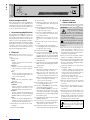 4
4
-
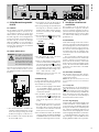 5
5
-
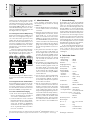 6
6
-
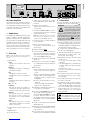 7
7
-
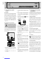 8
8
-
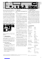 9
9
-
 10
10
-
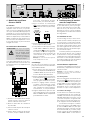 11
11
-
 12
12
-
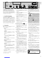 13
13
-
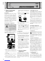 14
14
-
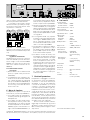 15
15
-
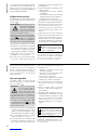 16
16
-
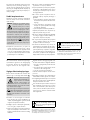 17
17
-
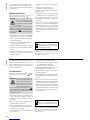 18
18
-
 19
19
-
 20
20


Monacor PA-1500D Benutzerhandbuch
- Kategorie
- Komponenten von Sicherheitsgeräten
- Typ
- Benutzerhandbuch
in anderen Sprachen
- English: Monacor PA-1500D User manual
- français: Monacor PA-1500D Manuel utilisateur
- italiano: Monacor PA-1500D Manuale utente
Andere Dokumente
-
RCS BAN-120 Bedienungsanleitung
-
-
RCS VLZ-6120A-6240A-6480A-6600A Bedienungsanleitung
-
-
RCS BA-4120-4240DP Bedienungsanleitung
-
-
-
-