
OPERATING INSTRUCTIONS / BEDIENUNGSANLEITUNG
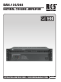
BAN-120/240
NATURAL COOLING AMPLIFIER
- ENGLISH
- DEUTSCH
120 W
240 W
fanless-cooling

2
SAFETY INSTRUCTIONS BAN-120/240
Electromagnetic compatibility and low-voltage guidelines: RC S leaves all devices and products, which are subject to the CE guidelines by certified test laboratories test.
By the fact it is guaranteed that you may sell our devices in Germany and in the European Union domestic market without additional checks.
Elektromagnetische Verträglichkeit und Niederspannungsrichtlinien: RC S läßt alle Geräte und Produkte, die den CE-Richtlinien unterliegen durch zertifizierte Prüflabors
testen. Dadurch ist sichergestellt, dass Sie unsere Geräte in Deutschland und im EU-Binnenmarkt ohne zusätzliche Prüfungen verkaufen dürfen.
AUSPACKEN UND KONTROLLE DES PRODUKTS
Bitte überprüfen Sie das Gerät sofort auf evtl. Transportschä-
den. Jedes RCS Produkt wird vor dem Verpacken sorgfältig
überprüft und in einem speziell dafür vorgesehenen Karton
geliefert.
Alle Transportschäden müssen sofort bei der Transport-
firma reklamiert werden!
Rücksendung: Wenn es nötig sein sollte ein defektes Gerät
zurückzusenden, nehmen Sie bitte Kontakt mit Ihrem Händ-
ler auf. Bitte versenden sie alle Rücksendungen in der Origi-
nalverpackung.
INSPECTION AND INVENTORY OF THE PRODUCT
Check unit carefully for damage which may have occurred
during transport. Each RCS product is carefully inspected
at the factory and packed in a special carton for safe
transport.
Notify the freight carrier immediately if you observe any
damage to the shipping carton or product!
Return: Repack the unit in the carton and await inspection
by the carrier’s claim agent. Notify your dealer of the pending
freight claim. Returning your unit for service or repairs.
Should your unit require service, contact your dealer.
WICHTIGE SICHERHEITSHINWEISE
Bitte lesen Sie die Sicherheitsanweisungen, bevor Sie
das Gerät in Betrieb nehmen.
1. Installation nach folgenden Richtlinien:
• StellenSiedasGerätimmeraufeineebeneundstabile
Unterfläche.
• WählenSieeinetrockeneUmgebungundvermeidenSie
Aufstellungsorte mit geringer Luftzufuhr.
• VermeidenSiediedirekteNähezuHeizungenundande-
ren Hitzequellen.
• Bei Einbau in einen19“ Gestellschrank ordnen Sie die
Geräte so an, daß eine ausreichende Belüftung gewähr-
leistet wird.
2. Bitte beachten Sie folgendes, wenn Sie das Gerät
anschließen:
• UmBedienfehlerzuvermeiden,lesenSiebittezuerstdie
Anleitung sorgfältig.
• ÖffnenSieniemalsdasGehäuse,ohnevorherdenNetz-
stecker zu ziehen.
• SchließenSiedasGerätnuran230VNetzspannung.
SAFETY INSTRUCTION
Please read all safety instructions before operating the
Device.
1. Installation according to the following guidelines:
• Installthedevicealwaysonaflatandevensurface.
• The device should not be exposed to damp or wet
surroundings. Please keep away from water.
• Pleaseavoidusingthedevicenearheatsources,suchas
radiators or other devices which produce heat.
• Toinstallthedeviceina19”rackpleasenotethattheap-
pliance should be situated, that the location or position
does not interfere with an adequate ventilation.
2. Keep in mind the following when connecting the
device:
• Connect the amplifier after reading the manuals.
• Topreventelectricshock,donotopentopcover.
• Connectonlyto230V
CAUTION / ACHTUNG
Caution: to reduCe the risk of eleCtriC shoCk do not remove
Cover (or BaCk) no user-serviCeaBle parts inside refer ser-
viCiing to qualified personnel.
aChtung: Zur vermeidung von stromsChlägen gehäuseaB-
deCkung oder rüCkseite niCht entfernen. keine vom Benut-
Zer Wartenden teile im inneren. Wartung nur durCh qualifi-
Ziertem personal.

3
BAN-120/240 CONTENTS
BAN-120/240
GENERAL REFERENCES / Allgemeine HinWeiSe
.......................................... 2
BAN-120/240 FRONT PANEL / FrontAnSiCHt
......................................... 4
BAN-120/240 REAR VIEW / rÜCKAnSiCHt............................................. 5
FD-20 PILOTTONE-MODULE / Pilotton-moDUl
................................ 6
FM-30 ERROR MONITORING MODULE / FeHler melDe-moDUl .................. 7
BAN-120/240 CONNECTING THE AMPLIFIER / VerStÄrKer AnSCHlieSSen
............. 8
BAN-120/240 OPERATION / inBetrieBnAHme ........................................11
BAN-120/240 SPECIFICATIONS / teCHniSCHe DAten
.................................11
CONTENTS / INHALT

4
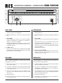
OPERATING ELEMENTS / CONNECTIONS BAN-120/240
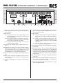
FRONT PANEL
1. Level indication for the power amplifier in case of over-
load, the red LED CLIP will light up
2. Volume control for the signal at the input PGM INPUT
(11)
3. Status LEDs
FAULT will light up if a fault has occurred in the amplifier
PROTECT will light up if the amplifier is overheated or a
fault has occurred in the amplifier
PRIORITY will light up if the amplifier is switched over to
thePRIORITYINPUT(16)viatheterminalPRICTL(14)
POWER power LED
4. POWER switch
Note: If a 24 V voltage from an emergency power supply
unitisappliedtotheterminalDCPOWER(6),itwillnotbe
possible to switch off the amplifier.
FRONTANSICHT
1. Pegelanzeige für die Endstufe bei Übersteuerung leuchtet
die rote LED CLIP
2. Lautstärkeregler für das Signal am Eingang PGM INPUT
(11)
3. Status-LEDs
FAULT leuchtet, wenn ein Fehler im Verstärker aufgetreten
ist
PROTECT leuchtet, wenn der Verstärker überhitzt oder
ein Fehler im Verstärker aufgetreten ist
PRIORITY leuchtet, wenn der Verstärker über den An-
schlussPRICTL(14)aufdenEingangPRIORITYINPUT
(16)umgeschaltetist
POWER Betriebsanzeige
4. Ein-/Ausschalter POWER
Hinweis: Liegt eine 24-V-Spannung von einer Notstrom-
einheitamAnschlussDCPOWER(6)an,lässtsichder
Verstärker nicht ausschalten.
RüCKANSICHT
Hinweis: Alle grünen Anschlussleisten lassen sich zu besseren
Handhabung beim Festschrauben der Anschlussleitungen von
ihren Steckverbindungen abziehen.
5. NetzbuchsezumAnschlussaneineSteckdose(230V/50Hz)
über das beiliegende Netzkabel
6. Anschlüsse DC POWER für eine 24-V-Notstromeinheit
7. Abdeckblech, wird beim Einsetzen des Fehlerüberwa-
chungsmodulsFM-30entfernt
8. Die Relaiskontakte schalten um, wenn der Verstärker über
denAnschlussPRICTL(14)aufdenEingangPRIORITY
INPUT(16)umgeschaltetwird
9. Lautsprecheranschlüsse
10. Abdeckblech, wird beim Einsetzen des Fehlerüberwa-
chungsmodulsFD-20entfernt
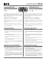
REAR PANEL
Note: To facilitate handling when screwing on the connection
cables, all green terminal strips can be disconnected from
their plug-in connections.
5. Mainsjackforconnectiontoasocket(230V/50Hz)viathe
mains cable supplied
6. Terminals DC POWER for a 24 V emergency power supply
7. Cover plate, to be removed when inserting the fault de-
tectionmoduleFM-30
8. The relay contacts will switch over if the amplifier is swit-
chedovertothePRIORITYINPUT(16)viatheterminal
PRICTL(14)
9. Speaker terminals
10. Cover plate, to be removed when inserting the fault de-
tectionmoduleFD-20
G
SPEAKER
OUTPUT
COM
25 V
50 V
100 V
PGM
INPUT
OUT
PRI
CTL
GND+24V
G
SPEAKER
OUTPUT
COM
25 V
50 V
100 V
PGM
INPUT
OUT
PRI
CTL
GND+24V
AMP 1
G
PRIORITY
INPUT
G
PRIORITY
INPUT
AMP 2
PGM
INPUT
PRIORITY
INPUT
. . . . . . .
max.
240W
RMS
PRIORITY
CONTROL
123 4
OUTPUT LEVEL LEVEL STATUS
FA ULT
PROTECT
PRIORITY
POWER
010
CLIP
0
-3
-8
-13
BAN-120
NATURAL COOLING P.A. AMPLIFIER
POWER
G
230 V~/50 Hz DC POWER
24 V4 /10A
PRIORITY
RELAY
CONTACT
MAX 3A
SPEAKER
OUTPUT
COM
25 V
50 V
100 V
COM
5.2
20.8
83.3
PGM
INPUT
0dBu (0.775V)
60 kΩ BAL
OFF
ON
400 Hz
FD-20
NORMAL
PILOT TONE
ON:NORMAL
OFF: FAULT
MAX 0.5A
G
0dBu (0.775 V)
60 kΩ BAL
PRIORITY
INPUT
LEVEL
SLAV E
INPUT
100V 0
010
OUT
PRI
CTL
GND+24V
5678 91011121314151617
Fault Detector
COM HOT
Line In
Test
RMS 2Vac
Sensitivity
maxmin
OSC Level
FD-20
18 19 20 21 22 23
SW1
ON OFF
CN601
G
SPEAKER
OUTPUT
COM
25 V
50 V
100 V
PGM
INPUT
OUT
PRI
CTL
GND+24V
G
SPEAKER
OUTPUT
COM
25 V
50 V
100 V
PGM
INPUT
OUT
PRI
CTL
GND+24V
G
SPEAKER
OUTPUT
COM
25 V
50 V
100 V
PGM
INPUT
OUT
PRI
CTL
GND+24V
G
SPEAKER
OUTPUT
COM
25 V
50 V
100 V
PGM
INPUT
G
PRIORITY
INPUT
OUT
PRI
CTL
GND+24V
AMP 1
G
PRIORITY
INPUT
G
PRIORITY
INPUT
G
PRIORITY
INPUT
AMP 2
AMP 3
AMP 4
PGM
INPUT
PRIORITY
INPUT
. . . . . . .
max.
480W
RMS
PRIORITY
CONTROL
AC DC FAN
FM-30 FAULT MONITOR MODULE
24 25

5
BAN-120/240 OPERATING ELEMENTS / CONNECTIONS
G
SPEAKER
OUTPUT
COM
25 V
50 V
100 V
PGM
INPUT
OUT
PRI
CTL
GND+24V
G
SPEAKER
OUTPUT
COM
25 V
50 V
100 V
PGM
INPUT
OUT
PRI
CTL
GND+24V
AMP 1
G
PRIORITY
INPUT
G
PRIORITY
INPUT
AMP 2
PGM
INPUT
PRIORITY
INPUT
. . . . . . .
max.
240W
RMS
PRIORITY
CONTROL
123 4
OUTPUT LEVEL LEVEL STATUS
FA ULT
PROTECT
PRIORITY
POWER
010
CLIP
0
-3
-8
-13
BAN-120
NATURAL COOLING P.A. AMPLIFIER
POWER
G
230 V~/50 Hz DC POWER
24 V4 /10A
PRIORITY
RELAY
CONTACT
MAX 3A
SPEAKER
OUTPUT
COM
25 V
50 V
100 V
COM
5.2
20.8
83.3
PGM
INPUT
0dBu (0.775V)
60 kΩ BAL
OFF
ON
400 Hz
FD-20
NORMAL
PILOT TONE
ON:NORMAL
OFF: FAULT
MAX 0.5A
G
0dBu (0.775 V)
60 kΩ BAL
PRIORITY
INPUT
LEVEL
SLAV E
INPUT
100V 0
010
OUT
PRI
CTL
GND+24V
5678 91011121314151617
Fault Detector
COM HOT
Line In
Test
RMS 2Vac
Sensitivity
maxmin
OSC Level
FD-20
18 19 20 21 22 23
SW1
ON OFF
CN601
G
SPEAKER
OUTPUT
COM
25 V
50 V
100 V
PGM
INPUT
OUT
PRI
CTL
GND+24V
G
SPEAKER
OUTPUT
COM
25 V
50 V
100 V
PGM
INPUT
OUT
PRI
CTL
GND+24V
G
SPEAKER
OUTPUT
COM
25 V
50 V
100 V
PGM
INPUT
OUT
PRI
CTL
GND+24V
G
SPEAKER
OUTPUT
COM
25 V
50 V
100 V
PGM
INPUT
G
PRIORITY
INPUT
OUT
PRI
CTL
GND+24V
AMP 1
G
PRIORITY
INPUT
G
PRIORITY
INPUT
G
PRIORITY
INPUT
AMP 2
AMP 3
AMP 4
PGM
INPUT
PRIORITY
INPUT
. . . . . . .
max.
480W
RMS
PRIORITY
CONTROL
AC DC FAN
FM-30 FAULT MONITOR MODULE
24 25
11. Symmetrischer Line-Signaleingang für normale Durchsa-
gen und Hintergrundmusik Empfindlichkeit für Vollaus-
steuerung0,775V(0dBu)
12. DIP-Schalter
Nr.1zumEin-undAusschaltendes400-Hz-Hochpasses
(senkt zur besseren Sprachverständlichkeit die Bäs-
seab)
Nr.2untere Position ON (Werkseinstellung), wenn das
Fehlerüberwachungsmodul FD-20 (Zubehör) nicht
eingebaut ist obere Position OFF, wenn das Modul
eingebaut ist
Nr.3zum Ein- und Ausschalten des 20-kHz-Testtons,
wenndasModulFD-20eingebautist
13. Kontroll-LED: leuchtet, wenn der Verstärker ordnungsge-
mäß arbeitet
14. Anschlüsse OUT für den 24-V-Ausgang (Spannung liegt
bei eingeschaltetem Verstärker immer an; belastbar mit
0,5A)undAnschlüssePRICTLfüreinenVorrangschalter:
bei geschlossenem Vorrangschalter schaltet der Verstärker
vomEingangPGMINPUT(11)aufdenEingangPRIORITY
INPUT(16)um
15. Lautstärkeregler für das Signal am Eingang PRIORITY
INPUT(16)
16. Symmetrischer Line-Signaleingang für wichtige Durchsa-
gen–sieheauchPositionen14und15;Empfindlichkeit
fürVollaussteuerung0,775V(0dBu)
17. Alternativer Eingang SLAVE INPUT zum Anschluss an eine
100-V-Lautsprecherleitung
11. Balanced line signal input for ordinary announcements
and background music; sensitivity for rated output power
0.775V(0dBu)
12. DIP switches
No.1to activate/deactivate the 400Hz highpass filter
(will attenuate the bass frequencies to improve the
speechintelligibility)
No.2lowerpositionON(factorysetting)ifthefaultdetec-
tionmoduleFD-20(accessory)isnotinstalledupper
position OFF if the module is installed
No.3to activate/deactivate the 20kHz test tone if the
moduleFD-20isinstalled
13. Indicating LED; will light up if the amplifier operates cor-
rectly
14. Terminals OUT for the 24 V output (voltage is always
applied when the amplifier is switched on; current rating
0.5A)andterminalsPRICTLforapriorityswitch:ifthe
priority switch is closed, the amplifier will switch over from
thePGMINPUT(11)tothePRIORITYINPUT(16)
15. Volume control for the signal at the PRIORITY INPUT
(16)
16. Balanced line signal input for important announcements.
alsoseeitems14and15;sensitivityforratedoutputpower
0.775V(0dBu)
17. AlternativeSLAVEINPUTforconnectiontoa100Vspeaker
cable

6
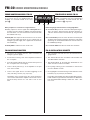
PILOTTONE-MODULE FD-20
PILOTTONE-MODULE (FD-20)
The Pilottone module is available as an ac-
cessory and is not supplied with the am-
plifier. It is inserted instead of the cover
plate
G.
The fault detection mudule of power amplifier checks ope-
rating conditions of amplifier and disconnection of speaker
wiringbygivingoutthesinewaveof20kHzatanouputlevel
of2Vrms(at70or100Vline).
Terminals for connection of signal devices:
18. Relay output to connect a signal device
19. Terminals COM and HOT; connect to the terminals
SPEAKER OUTPUT (9): HOT to 100 V and COM to
COM
20. Measuring points to adjust the response sensitivity
21. Controlforthe20kHztesttonelevel22Controlforthe
response sensitivity
FD-20 INSTALLATION STEPS
1. UnplugthepowercablefromaACoutlet.
2. Remove the rear mounted black panel, and mount the
FD-20intheresultantholeusingscrewssupplied with
the module.
3. Set„ON“positionMS1ontheFD-20moduleaftercon-
nectionofCN601ontheFD-20.
4. SettheFD-20switchbesidetheprogramentryofposi-
tion„FD-20“.
5. Connect„COM“ofAMPoutputterminaland100Vtermi-
naltothe„COM“and„HOT“.
6. Connect relay contact of FD-20 to the input terminal
of relay contact of FS-381. (FAULT STAND-BY AMP
SWITCH)
CALIBRATING FD-20 ON POWER AMPLIFIERS
Ensure amplifier to be adjusted in not being used, I.e. Un-
plug the PGM and PRIORITY input screw terminals.
1. Set Digital Portable Multimeter to measure AC voltage
andconnectacrosspoweramplifierCOMand70V/100V
terminals. Confirm output of power amplifiers is 2VAC
rms at 20 kHz. Adjust „OSC LEVEL“ potentiometer
(VR602),ifnecessary.
2. Set Digital Portable Multimeter to measure AC voltage
andconnect„TEST“connector.Confirmreadingof2VAC
rmsat20kHz.Adjust„Sensitivity“potetiometer(VR601),
if necessary. Insert PGM and PRIORITY inputt screw ter-
minals if removed.
PILOTTON-MODULE (FD-20)
DasPilottoneistalsZubehörerhältlichund
gehört nicht zum Lieferumfang des Verstär-
kers. Es wird anstelle des Abdeckbleches
eingesetzt
G.
Das Überwachungsmodul überprüft die Funktion des Ver-
stärkers und das Fehlen der Lautsprecherleitung, indem es
ein20kHzSinussignalmiteinerSpannungvon2V(bei70or
100VLinie)ausgibt.
Anschlüsse zum Anschluss von Signalgebern:
18. Relaisausgang zum Anschluss eines Signalgebers
19. Anschlüsse COM und HOT; mit den Anschlüssen SPEA-
KEROUTPUT(9)verbinden:HOTan100VundCOMan
COM
20. Messpunkte zum Einstellen der Ansprechempfindlichkeit
21.Reglerfürden20-kHz-Testtonpegel22ReglerfürdieAn-
sprechempfindlichkeit
FM-20 INSTALLATIONS SCHRITTE
1. TrennenSiedasGerätvomNetz.
2. Entfernen Sie die Blende auf der Rückseite und befesti-
genSiedasFD-20ModulmitdenbeigefügtenSchrau-
ben.
3. SetzenSiedenJumperSW1aufONundverbindendas
angehängte Kabel von der Leerblende mit dem Steck-
platzCN601.
4. SetzenSiedenFD-20-SchalternebendemProgrammein-
gangaufdie„FD-20“-Position.
5. VerbindenSieden„LineIn“KontaktamFD-20mitdem
100VAusgangderjeweiligenEndstufe.
6. Verbinden Sie den Störmeldeausgang des FD-20 mit
demStörmeldeeingangdesFS-381.(Havarieumschalter)
KALIBRIERUNG DES FD-20 MODULS
Stellen Sie sicher dass die Endstufe in Ordnung ist und kei-
ne Signale anliegen. Stecken sie sicherheitshalber die Pro-
gramm- und Priritätseingänge ab.
1. SellenSieIhrDigitalmultimeteraufACundschließenSie
esparallelaufdie100V-LeitungderEndstufe.
JustierenSiemitdem„OSCLEVEL“Potentiometer(VR
602)dieSpannungauf2VACRMSbei20kHz.
2. SchließenSienun das Multimeteranden„TEST“-Aus-
gangdesFD-20Modulsundjustierensiegegebennen-
falls die Spannung an dem „Sensitivity“ Potentiometer
auf 2 VAC RMS. Als letzten Schritt schließen Sie die Ein-
gangssignale wieder an die Endstufe.
G
SPEAKER
OUTPUT
COM
25 V
50 V
100 V
PGM
INPUT
OUT
PRI
CTL
GND+24V
G
SPEAKER
OUTPUT
COM
25 V
50 V
100 V
PGM
INPUT
OUT
PRI
CTL
GND+24V
AMP 1
G
PRIORITY
INPUT
G
PRIORITY
INPUT
AMP 2
PGM
INPUT
PRIORITY
INPUT
. . . . . . .
max.
240W
RMS
PRIORITY
CONTROL
123 4
OUTPUT LEVEL LEVEL STATUS
FA ULT
PROTECT
PRIORITY
POWER
010
CLIP
0
-3
-8
-13
BAN-120
NATURAL COOLING P.A. AMPLIFIER
POWER
G
230 V~/50 Hz DC POWER
24 V4 /10A
PRIORITY
RELAY
CONTACT
MAX 3A
SPEAKER
OUTPUT
COM
25 V
50 V
100 V
COM
5.2
20.8
83.3
PGM
INPUT
0dBu (0.775V)
60 kΩ BAL
OFF
ON
400 Hz
FD-20
NORMAL
PILOT TONE
ON:NORMAL
OFF: FAULT
MAX 0.5A
G
0dBu (0.775 V)
60 kΩ BAL
PRIORITY
INPUT
LEVEL
SLAV E
INPUT
100V 0
010
OUT
PRI
CTL
GND+24V
5678 91011121314151617
Fault Detector
COM HOT
Line In
Test
RMS 2Vac
Sensitivity
maxmin
OSC Level
FD-20
18 19 20 21 22 23
SW1
ON OFF
CN601
G
SPEAKER
OUTPUT
COM
25 V
50 V
100 V
PGM
INPUT
OUT
PRI
CTL
GND+24V
G
SPEAKER
OUTPUT
COM
25 V
50 V
100 V
PGM
INPUT
OUT
PRI
CTL
GND+24V
G
SPEAKER
OUTPUT
COM
25 V
50 V
100 V
PGM
INPUT
OUT
PRI
CTL
GND+24V
G
SPEAKER
OUTPUT
COM
25 V
50 V
100 V
PGM
INPUT
G
PRIORITY
INPUT
OUT
PRI
CTL
GND+24V
AMP 1
G
PRIORITY
INPUT
G
PRIORITY
INPUT
G
PRIORITY
INPUT
AMP 2
AMP 3
AMP 4
PGM
INPUT
PRIORITY
INPUT
. . . . . . .
max.
480W
RMS
PRIORITY
CONTROL
AC DC FAN
FM-30 FAULT MONITOR MODULE
24 25

7
FM-30 ERROR MONITORING MODULE
FEHLER MELDE-MODUL FM-30
Das Fehlermeldemodul ist als Zubehör er-
hältlich und gehört nicht zum Lieferumfang
des Verstärkers. Es wird anstelle des Ab-
deckbleches
J eingesetzt.
Relaisausgänge zum Anschluss von Signalgebern:
23. Das Relais AC spricht an, wenn keine Netzspannung an-
liegt, die interne Netzsicherung durchgeschmolzen ist
oderdasGerät mit demNetzschalter(4)ausgeschaltet
ist.
24. Das Relais DC spricht an, wenn die interne Sicherung für
die Notstromversorgung durchgeschmolzen ist oder keine
Spannung von einer Notstromeinheit an den Anschlüssen
DCPOWER(6)anliegt.
25. Das Relais FAN ist bei diesem Gerät ohne Funktion.
FM-30 INSTALLATIONS SCHRITTE
1. Den Verstärker vom Netzund von der Notstromversor-
gung trennen.
2. Den Gehäusedeckel des Verstärkers abschrauben und
das Abdeckblech entfernen.
3. DasModulFM-30anderStelledesAbdeckblechsvon
außen einsetzen und festschrauben.
4. Die 6-poligeLeitung (C) des Verstärkers in die Buchse
CN5desModulsstecken.
5. DieSignalgeberzurAlarmierungandieRelaisumschalt-
kontakte(23),(24) oder(25) anschließen.
Der Aufdruck am Modul zeigt die Kontaktstellung im Feh-
lerfall und bei ausgeschaltetem Verstärker. Die Belastbar-
keitderRelaiskontaktebeträgt1Abeimax.120V~oder
max.24V.
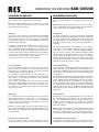
ERROR MONITORING MODULE FM-30
The fault monitoring module is available as
an accessory and is not supplied with the
amplifier. It is inserted instead of the cover
plate
J.
Relay outputs for connection of signal devices:
23. Relay outputs to connect signal devices Relay AC will re-
spond if no mains voltage is applied, if the internal mains
fuse has blown, or if the unit has been switched off with
thePOWERswitch(4).
24. Relay DC will respond if the internal fuse for the emer-
gency power supply has blown or if no voltage from an
emergency power supply unit is applied to the terminals
DCPOWER(6).
25. Relay FAN is without function on this unit.
FM-30 INSTALLATION STEPS
1. Disconnect the amplifier from the mains and from the
emergency power supply.
2. Screw off the housing cover of the amplifier and remove
the cover plate.
3. InsertthemoduleFM-30fromtheoutsideattheplaceof
the cover plate and screw it tightly.
4. Connect the 6-poleline(C) of the amplifierto the jack
CN5ofthemodule.
5. Connect the signal devices for alarm triggering to the
relayswitchingcontacts(23),(24) or(25).
The imprint on the module shows the contact position in
cause of fault and with the amplifier switched off. The ra-
tingoftherelaycontactsis1Aat120V~max.or24V
max.
G
SPEAKER
OUTPUT
COM
25 V
50 V
100 V
PGM
INPUT
OUT
PRI
CTL
GND+24V
G
SPEAKER
OUTPUT
COM
25 V
50 V
100 V
PGM
INPUT
OUT
PRI
CTL
GND+24V
AMP 1
G
PRIORITY
INPUT
G
PRIORITY
INPUT
AMP 2
PGM
INPUT
PRIORITY
INPUT
. . . . . . .
max.
240W
RMS
PRIORITY
CONTROL
123 4
OUTPUT LEVEL LEVEL STATUS
FA ULT
PROTECT
PRIORITY
POWER
010
CLIP
0
-3
-8
-13
BAN-120
NATURAL COOLING P.A. AMPLIFIER
POWER
G
230 V~/50 Hz DC POWER
24 V4 /10A
PRIORITY
RELAY
CONTACT
MAX 3A
SPEAKER
OUTPUT
COM
25 V
50 V
100 V
COM
5.2
20.8
83.3
PGM
INPUT
0dBu (0.775V)
60 kΩ BAL
OFF
ON
400 Hz
FD-20
NORMAL
PILOT TONE
ON:NORMAL
OFF: FAULT
MAX 0.5A
G
0dBu (0.775 V)
60 kΩ BAL
PRIORITY
INPUT
LEVEL
SLAV E
INPUT
100V 0
010
OUT
PRI
CTL
GND+24V
5678 91011121314151617
Fault Detector
COM HOT
Line In
Test
RMS 2Vac
Sensitivity
maxmin
OSC Level
FD-20
18 19 20 21 22 23
SW1
ON OFF
CN601
G
SPEAKER
OUTPUT
COM
25 V
50 V
100 V
PGM
INPUT
OUT
PRI
CTL
GND+24V
G
SPEAKER
OUTPUT
COM
25 V
50 V
100 V
PGM
INPUT
OUT
PRI
CTL
GND+24V
G
SPEAKER
OUTPUT
COM
25 V
50 V
100 V
PGM
INPUT
OUT
PRI
CTL
GND+24V
G
SPEAKER
OUTPUT
COM
25 V
50 V
100 V
PGM
INPUT
G
PRIORITY
INPUT
OUT
PRI
CTL
GND+24V
AMP 1
G
PRIORITY
INPUT
G
PRIORITY
INPUT
G
PRIORITY
INPUT
AMP 2
AMP 3
AMP 4
PGM
INPUT
PRIORITY
INPUT
. . . . . . .
max.
480W
RMS
PRIORITY
CONTROL
AC DC FAN
FM-30 FAULT MONITOR MODULE
24 25

8
CONNECTING THE AMPLIFIER BAN-120/240
VERSTäRKER ANSCHLIESSEN
Alle Anschlüsse sollten nur durch Fachpersonal und unbe-
dingt bei ausgeschaltetem Verstärker vorgenommen wer-
den!
Hinweis: Alle grünen Anschlussleisten lassen sich zu bes-
seren Handhabung beim Festschrauben der Anschlusslei-
tungen von ihren Steckverbindungen abziehen.
Lautsprecher
Die 100-V-Lautsprecher mit der Anschlussleiste SPEAKER
OUTPUT(9)verbinden:dieMinuspolemitdemKontaktCOM
unddiePluspolemitdemKontakt100V.Hierbeidarfeine
Gesamtbelastung von 120 WRMS durch die Lautsprecher
nicht überschritten werden, sonst wird der Verstärker be-
schädigt.
Um die Verstärkerleistung zu verdoppeln oder zu vervierfa-
chen,lassensichzweibzw.vierBAN-120inSerieschalten,
siehe Abb. 5 und6. Dabei jeweils alle Eingänge PGM IN-
PUT(11)parallelschalten,alleEingängePRIORITYINPUT
(16) und alle Steuereingänge PRI CTL (14). Damit die Ver-
stärker untereinander gleich belastet werden, die Lautstär-
kereglerLEVEL(2)aufdenFrontseitenindiegleichePosition
stellen.DieLautstärkereglerLEVEL(15)aufdenRückseiten
ebenfalls in die gleiche Position stellen.
Line-Signaleingänge
Für Durchsagen und Musikwiedergabe wird ein ELA-Vorver-
stärker benötigt, an den Mikrofone und Audiogeräte (z. B.
CD-Spieler,Radiogerät)angeschlossenwerdenkönnen.Den
Ausgang des Vorverstärkers mit dem Eingang PGM INPUT
(11)verbinden.
Für Notfalldurchsagen oder andere wichtige Durchsagen ist
derBAN-120mitdemEingangPRIORITYINPUT(16)ausge-
stattet.SobaldeinmitdenKlemmenPRICTL(14)verbun-
dener Vorrangschalter oder verbundenes Relais geschlos-
sen wird, schaltet der Verstärker vom Eingang PGM INPUT
auf den Eingang PRIORITY INPUT um und es ist nur die Not-
falldurchsage zu hören. Die Lautstärke für Notfalldurchsagen
wirdseparatmitdemReglerLEVEL(15)aufderRückseite
eingestellt.
100-V-Eingang
Alternativ zu den Line-Signaleingängen (11) und (16) kann
der 100-V-Eingang SLAVE INPUT (17) verwendet werden,
um z. B. bei einer bestehenden ELA-Anlage zusätzliche Lei-
stung für weitere Lautsprecher zu erhalten. Die Klemmen
SLAVE INPUT an die 100-V-Lautsprecherleitung der ELA-
Anlage anschließen.
Hinweis: DieReglerLEVEL(2) und (15) beeinflussen nicht
die Lautstärke des Signals, das am Eingang SLAVE INPUT
anliegt. Die Signallautstärke an dem Verstärker einstellen,
vondemdas100-V-SignalaufdenBAN-120gegebenwird.
Vorrangrelais und 24-V-Ausgang
SobaldeinmitdenKlemmenPRICTL(14)verbundenerVor-
rangschalter oder verbundenes Relais geschlossen wird,
CONNECTING THE AMPLIFIER
Any connection should only be made by skilled personnel;
always switch off the amplifier before connecting!
Note: To facilitate handling when screwing on the connec-
tion cables, all green terminal strips can be disconnected
from their plug-in connections.
Speakers
Connectthe100VspeakerstotheterminalstripSPEAKER
OUTPUT(9):connectthenegativepolestothecontactCOM
andthepositivepolestothecontact100V.Thetotalload
bythespeakersmustnotexceed120WRMS,otherwisethe
amplifier will be damaged.
To double or quadruple the amplifier power, connect two or
fourBAN-120unitsinseries,seefigs.5and6.Respectively
connectinparallelallinputsPGMINPUT(11),allinputsPRI-
ORITYINPUT(16),andallcontrolinputsPRICTL(14).Toen-
sure that the load is uniformly distributed on the amplifiers,
setthevolumecontrolsLEVEL(2)onthefrontpanelstothe
same position. Set the volume controls LEVEL
(15)ontherearsidesalsotothesameposition.
Line signal inputs
For announcements and music reproduction, a PA pream-
plifier is required which allows to connect microphones and
audiounits(e.g.CDplayer,radioset).Connecttheoutputof
thepreamplifiertothePGMINPUT(11).
For emergency announcements or other important an-
nouncements,theBAN-120isequippedwiththePRIORITY
INPUT(16).Assoonasapriorityswitchorarelayconnected
to the terminals PRI CTL
(14)isclosed, the amplifierwillswitchover fromthePGM
INPUT to the PRIORITY INPUT and only the emergency an-
nouncement will be audible. The volume for emergency an-
nouncements is separately adjusted with the control LEVEL
(15)ontherearside.
100 V input
Asanalternativetothelinesignalinputs(11)and(16),the
100VSLAVEINPUT(17)canbeused,e.g.toprovidead-
ditionalpowerforfurtherspeakersincaseofanexistingPA
system.ConnecttheterminalsSLAVEINPUTtothe100V
speaker cable of the PA system.
Note: ThecontrolsLEVEL(2)and(15)willnotaffectthevo-
lume of the signal applied to the SLAVE INPUT. Adjust the si-
gnalvolumeontheamplifierwhichwillfeedthe100Vsignal
totheBAN-120.
Priority relay and 24 V output
As soon as a priority switch or a relay connected to the ter-
minalsPRICTL(14)isclosed,theinternalpriorityrelaywill

9
BAN-120/240 CONNECTING THE AMPLIFIER
schaltet das interne Vorrangrelais um. Über dessen An-
schlüssePRIORITYRELAY(8)lassensichweitereVorgänge
steuern, z. B. können ELA-Lautstärkeeinsteller mit Pflicht-
empfangsrelaisaufmaximaleLautstärkegeschaltetwerden.
Wird zum Schalten der Pflichtempfangsrelais eine 24-V-
Spannung benötigt, kann z. B. die Spannung von der Klem-
me+24V(14)überdieRelaiskontaktegeleitetwerden.Die
24-V-Spannungistmit500mAbelastbarundlässtsichauch
für andere Anwendungen nutzen.
Strom- und Notstromversorgung
1) SollderVerstärkerbeieinemNetzausfallweiterarbeiten,
dieAnschlüsseDCPOWER(6)miteiner24-V-Notstrom-
einheit(z.B.ESP-500vonRCS)verbinden.BeieinerKa-
bellänge bis 4m ist ein Kabelquerschnitt von mindestens
5mm2erforderlich.
Hinweis: Liegt die 24-V-Spannung von der Notstromein-
heit an den Anschlüssen DC POWER an, lässt sich der
VerstärkermitdemSchalterPOWER(4)nichtausschal-
ten. Es wird lediglich zwischen Netz- und Notstromver-
sorgung umgeschaltet.
2) Zum Schluss das beiliegende Netzkabel zuerst in die
Netzbuchse(5)unddannineineSteckdose(230V~/50Hz)
stecken.
switchover.ItsterminalsPRIORITYRELAY(8)allowtocon-
trol further actions, e. g. switching PA attenuators with emer-
gencypriorityrelaytomaximumvolume.
If a 24 V voltage is required for switching the emergency pri-
orityrelays,e.g.thevoltagefromtheterminal+24(14)may
be fed to the relay contacts. The 24 V voltage has a current
rating of 500 mAand can alsobe used for otherapplica-
tions.
Power supply and emergency power supply
1) Forcontinuedoperationoftheamplifierincaseofmains
failure,connecttheterminalsDCPOWER(6)toa24V
emergencypowersupplyunit(e.g.ESP-500fromRCS).
Withamaximumcablelengthof4m,aminimumcable
crosssectionof5mm2isrequired.
Note: If the 24 V voltage from the emergency power sup-
ply unit is applied to the terminals DC POWER, it will not
be possible to switch off the amplifier with the POWER
switch(4);itisonlyswitchedoverbetweenmainssupply
and emergency power supply.
2) Finally connect the mains cable supplied to the mains
jack(5)firstandthentoasocket(230V~/50Hz).

10
NATURAL COOLING AMPLIFIER BAN-120/240
INBETRIEBNAHME
1) UmEinschaltgeräuschezuvermeiden,zuerstalleande-
ren Geräte der ELA-Anlage einschalten.
2) Vor dem ersten Einschalten desVerstärkers dieRegler
LEVEL(2)und(15)aufNullstellen,umzuAnfangeinezu
hohe Lautstärke zu vermeiden. Dann den Verstärker mit
demSchalterPOWER(4)einschalten.DieBetriebsanzei-
gePOWER(3)leuchtet.
3) Den Regler LEVEL (2) auf die gewünschte Lautstärke
einstellen. Bei Übersteuerung leuchtet die rote Anzeige
CLIPderPegelanzeige(1).DanndieLautstärkemitdem
Regler reduzieren.
4) Die Lautstärke für wichtige Durchsagen, die über den
EingangPRIORITYINPUT(16)aufdenVerstärkergege-
benwerden,mitdemReglerLEVEL(15)aufderGeräte-
rückseite einstellen. Dazu muss der Vorrangschalter (oder
dasRelais),der(das)mitdenKlemmenPRICTL(14)ver-
bunden ist, geschlossen werden. Die Anzeige PRIORITY
(3)leuchtetdannauf.
5) Für eine bessere Sprachverständlichkeit lässt sich mit
demDIP-SchalterNr.1(12)einHochpass(400Hz)ein-
schalten(PositionON).TieffrequenteStörgeräuschewer-
den damit unterdrückt.
6) DerVerstärkeristmiteinerSchutzschaltunggegenÜber-
hitzung, Überlastung und Kurzschluss an den Lautspre-
cherausgängen ausgestattet.
BeieinerÜberhitzungleuchtetdieAnzeigePROTECT(3)
auf. Bei Überlastung, einem Kurzschluss oder einem an-
deren Fehler leuchtet zusätzlich die Anzeige FAULT auf. In
jedem Fall wird der Verstärker stumm geschaltet. Leuch-
tet eine dieser Anzeigen auf, den Verstärker ausschalten
und den Fehler durch Fachpersonal beheben lassen.
IstdasFehlerüberwachungsmodulFD-20(Abb.3)nicht
eingesetzt,denDIP-SchalterNr.2(12)aufderVerstärker-
rückseite in die untere Position ON stellen, sonst spricht
die Schutzschaltung an.
OPERATION
1) To prevent switching noise, switch on all other units of
the PA system first.
2) Priortoswitchingontheamplifierforthefirsttime,set
thecontrolsLEVEL(2)and(15)tozerotopreventanex-
cessive volume at the beginning. Then switch on the am-
plifierwiththePOWERswitch(4).ThePOWERLED(3)
will light up.
3) SetthecontrolLEVEL(2)tothedesiredvolume.Incase
ofoverload,theredLEDCLIPofthelevelindication(1)
will light up. Then reduce the volume with the control.
4) Adjustthevolumeforimportantannouncements fedto
theamplifierviathePRIORITYINPUT(16)withthecon-
trolLEVEL(15)ontherearsideoftheunit.Forthispurpo-
se,thepriorityswitch(ortherelay)connectedtotheter-
minalsPRICTL(14)mustbeclosed.TheLEDPRIORITY
(3)willlightup.
5) Toimprovethespeechintelligibility,switchonahigh-pass
filter(400 Hz)withDIPswitchNo.1(12) [positionON].
Thus, low-frequency interference will be suppressed.
6) Theamplifierisequippedwithaprotectivecircuitagainst
overheating, overload, and short circuit at the speaker
outputs.Incase of overheating, the LED PROTECT(3)
will light up; in case of overload, a short circuit or another
defect, the LED FAULT will additionally light up. In any
case, the amplifier will be muted. If one of these LEDs
light up, switch off the amplifier and have the fault elimi-
nated by skilled personnel.
If the fault detection module PA-6FD (fig. 3) is not in-
serted,setDIPswitchNo.2(12)ontherearsideofthe
amplifier to the lower position ON, otherwise the protec-
tive circuit will respond.

11
TECHNICAL DATA / TECHNISCHE DATEN BAN-120 / 240
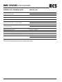
IRated Output (RMS) / BAN-120: 120W
Ausgangsleistung(RMS) BAN-240: 240W
Frequency Response / Frequenzgang Lessthan: -3dB(35-20.000Hz)
T.H.D / Klirrfaktor Lessthan0,5%(1kHz)
Signal to Noise Ratio / Rauschpegel Morethan95dB
Input Sensitivity - impedance (PGM) / 0dB(0,775V),60kOhm,symmetr.fürPGMundPRIO
Eingangsempfindlichkeit-Impedanz(PGM)
Power Consumption / BAN-120: 335W
Leistungsaufnahme BAN-240: 735W
Speaker Output / AusgängeLautsprecher 25V,50V,100V
Input Filter /Eingangsfilter 400Hz,-3dBHPF
Power Source / Spannungsversorgung AC/DCAC230V(50/60Hz),DC24V
Dimensions (WxHxD) / Abmessungen(BxHxT) 483x133x379mm;
Weight / Gewicht BAN-120: 15,5kg
BAN-240: 16,5kg
Specifications and Hardware design subject to change without notice.
Technische Änderungen der Hardware und des Gerätedesigns sind vorbehalten.
BAN-120/240 SPECIFICATIONS

© Copyright by RCS AUDIO-SYSTEMS GmbH.
Publication and duplication of the contained data only allowed with our strict permission. Veröffentlichung und Vervielfältigung der enthaltenen Daten, auch auszugsweise, nur mit unserer ausdrücklichen Genehmigung.
RCS19.10.2009
Hardware and Software specifications subject to change without notice.
Techische Änderungen in Hardware und Software vorbehalten.
NATURAL COOLING AMPLIFIER BAN-120/240
-
 1
1
-
 2
2
-
 3
3
-
 4
4
-
 5
5
-
 6
6
-
 7
7
-
 8
8
-
 9
9
-
 10
10
-
 11
11
-
 12
12


RCS BAN-120 Bedienungsanleitung
- Typ
- Bedienungsanleitung
- Dieses Handbuch eignet sich auch für
in anderen Sprachen
- English: RCS BAN-120 Owner's manual
Verwandte Artikel
-
RCS BA-2120-2240DP Bedienungsanleitung
-
RCS BA-4120-4240DP Bedienungsanleitung
-
-
RCS BA-600 DP Bedienungsanleitung
-
-
-
RCS VLZ-6120A-6240A-6480A-6600A Bedienungsanleitung
-
-
-