Airwell CD50 Installation and Maintenance Manual
- Kategorie
- Split-System-Klimaanlagen
- Typ
- Installation and Maintenance Manual
Seite wird geladen ...
Seite wird geladen ...
Seite wird geladen ...

2
Split system gainable à pression -
Ductable pressurized split system -
Split-system für Kanalanschluß unter Druck
MISE HORS TENSION
OBLIGATOIRE AVANT
TOUTES INTERVENTIONS
DANS LES BOITIERS
ELECTRIQUES
- Les informations contenues dans cette notice sont
sujettes à modifications sans préavis.
ECOMMANDATIONS
GENERALES
- Avant tout, merci d'avoir porté votre choix
sur un matériel A
irwell.
CONSEILS DE SECURITE
- Lorsque vous intervenez sur votre maté-
riel : suivez les règles de sécurité en vi-
gueur.
- L’installation et l’entretien du matériel de-
vront être effectués exclusivement par du
personnel qualifié selon les règles de l'art,
les normes et instructions en vigueur.
- Assurez-vous que l'alimentation électrique
disponible et la fréquence du réseau sont
adaptées au courant de fonctionnement né-
cessaire compte tenu des conditions spé-
cifiques de l’emplacement, et du courant
nécessaire à tout autre appareil branché
sur le même circuit.
AVERTISSEMENT
- Couper l'alimentation électrique générale
avant toute intervention ou opération d’en-
tretien.
- Le fabricant décline toute responsabilité et
la garantie ne sera plus valable si ces ins-
tructions d’installation ne sont pas respec-
tées.
- Si vous avez des difficultés, faites appel
au Service Technique de votre zone.
- Avant la mise en place, procédez si pos-
sible au montage des accessoires obliga-
toires ou non. (Voir notice livrée avec cha-
que accessoire) .
R
- Pour une meilleure connaissance du pro-
duit, nous vous conseillons de consulter
également notre notice technique .
ENERAL
RECOMMENDATIONS
- Congratulations for having selected an
A
irwell air conditioner.
SAFETY DIRECTIONS
- Follow the safety rules in force when you
are working on your appliance.
- Installation and maintenance of the
equipment must only be performed by
qualified specialists in accordance with the
rules of good workmanship and prevailing
standards and instructions.
- Make sure that the power supply and its
frequency are adapted to the required
electric current of operation, taking into
account specific conditions of the location
and the current required for any other
appliance connected with the same circuit.
WARNING
- Cutoff power supply before starting to work
on the appliance.
- The manufacturer declines any
responsibility and the warranty becomes
void if these instructions are not respected.
- If you meet a problem, please call the
Technical Department of your area.
- If possible, assemble the mandatory or
optional accessories before placing the
appliance on its final location.(see instruc-
tions provided with each accessory)
In order to become fully familiar with the
appliance, we suggest to read also our
Technical Instructions .
- The information contained in these Instructions are
subject to modification without advance notice.
G
IT IS MANDATYORY TO
CUTOFF POWER SUPPLY
BEFORE STARTING TO
WORK IN THE ELECTRIC
CASING BOXES.
VOR JEDEM EINGRIFF IN
DEN SCHALTSCHRÄNKEN
UNBEDINGT NETZSTECKER
ZIEHEN
A
LLGEMEINE
EMPFEHLUNGEN
- Zunächst danken wir Ihnen, daß Sie sich für
ein A
irwell Klimagerät entschieden haben.
SICHERHEITSANWEISUNGEN
- Bei Eingriffen an Ihrem Gerät sind die
geltenden Sicherheitsvorschriften zu
befolgen.
- Installation und Wartung der Ausrüstung
dürfen nur von qualifiziertem Personal
fachgemäß und entsprechend den
geltenden Normen und Vorschriften
vorgenommen werden.
- Vergewissern Sie sich, daß
Stromversorgung und Netzfrequenz dem
erforderlichen Betriebsstrom entsprechen,
wobei die spezifischen Bedingungen des
Aufstellungsorts und der erforderliche Strom
für die anderen, an den gleichen Stromkreis
angeschlossenen Geräte zu berücksichtigen
sind.
WARNUNG
- Vor jedem Eingriff oder vor Wartungsarbeiten
an dem Gerät muß der Strom abgeschaltet
werden. Bei Nichtbefolgen dieser
Anweisungen lehnt der Hersteller jede
Verantwortung ab, und die Garantie wird
ungültig. Bei Schwierigkeiten wenden Sie
sich bitte an den für Ihren Bezirk
zuständigen Technischen Kundendienst.
- Vor dem Aufstellen falls möglich die
vorgeschriebenen oder wahlfreien
Zubehörteile montieren. (Siehe die mit den
jeweiligen Zubehörteilen gelieferte
Anleitung).
Um mit dem Gerät besser vertraut zu
werden, empfehlen wir, auch unsere
Technische Beschreibung durchzulesen.
- Die in der vorliegenden Beschreibung enthaltenen
Informationen können ohne vorherige Mitteilung geändert
werden.

3
Split system gainable à pression -
Ductable pressurized split system -
Split-system für Kanalanschluß unter Druck
SOMMAIRE
DESCRIPTION
Généralités .............................................. 5-6
Caractéristiques générales ...................... 7-8
Dimensions des unités intérieures ........ 9-12
Dimensions des unités extérieures ... 13-15
INSTALLATION
Emplacement de l’unité extérieure .......... 16
Emplacement de l’unité intérieure ....... 17-18
Liaison frigorifique ............................... 19-22
Connexions électriques ...................... 23-25
Raccordements "display" ........................ 26
FONCTIONNEMENT
Maintenance ............................................. 27
SUMMARY
DESCRIPTION
General .................................................... 5-6
General Specifications ............................ 7-8
Dimensions of Indoor Units ................... 9-12
Dimensions of Outdoor Units ............. 13-15
INSTALLATION
Location of the Outdoor Unit .................... 16
Location of the Indoor Unit .................. 17-18
Refrigerant Line ................................... 19-22
Electrical Connections ........................ 23-25
Display Connections ................................ 26
MAINTENANCE
Scheduled Maintenance .......................... 27
INHALT
BESCHREIBUNG
Allgemeines ............................................. 5-6
Technische Daten .................................... 7-8
Abmessungen Innenteile ....................... 9-12
Abmessungen Außenteile ................... 13-15
INSTALLATION
Aufstellungsort Außenteil ......................... 16
Aufstellungsort Innenteil ...................... 17-18
Kältemittelverbindungsleitung ............. 19-22
Stromanschlüsse ................................ 23-25
«Display» Anschlüsse ............................. 26
WARTUNG
Wartung .................................................... 27

4
Split system gainable à pression -
Ductable pressurized split system -
Split-system für Kanalanschluß unter Druck
N° PRODUITS FINIS END PRODUCT PART NUMBERS
serueirétnisétinU
stinuroodnI
elietnennI
-serueirétxesétinU -stinuroodtuO elietneßuA
DRADNATS-ELBISREVER -PMUPTAEH .P.W
zH05V032~N1zH05V032~N1zH05V004~N3zH05V032~N1zH05V004~N3
71DC71DC
71DC
71DC71DCA210230PS7A210230PS7
A210230PS7
A210230PS7A210230PS771CG71CG
71CG
71CG71CG301160PS7301160PS7
301160PS7
301160PS7301160PS7
CR71CGCR71CG
CR71CG
CR71CGCR71CG401160PS7401160PS7
401160PS7
401160PS7401160PS7
22DC22DC
22DC
22DC22DCA310230PS7A310230PS7
A310230PS7
A310230PS7A310230PS722CG22CG
22CG
22CG22CG501160PS7501160PS7
501160PS7
501160PS7501160PS7 CR22CGCR22CG
CR22CG
CR22CGCR22CG601160PS7601160PS7
601160PS7
601160PS7601160PS7
62DC62DC
62DC
62DC62DCA410230PS7A410230PS7
A410230PS7
A410230PS7A410230PS762CG62CG
62CG
62CG62CG701160PS7701160PS7
701160PS7
701160PS7701160PS7 CR62CGCR62CG
CR62CG
CR62CGCR62CG801160PS7801160PS7
801160PS7
801160PS7801160PS7
53DC53DC
53DC
53DC53DCA510230PS7A510230PS7
A510230PS7
A510230PS7A510230PS753CG53CG
53CG
53CG53CG901160PS7901160PS7
901160PS7
901160PS7901160PS7T53CGT53CG
T53CG
T53CGT53CG011160PS7011160PS7
011160PS7
011160PS7011160PS7CR53CGCR53CG
CR53CG
CR53CGCR53CG111160PS7111160PS7
111160PS7
111160PS7111160PS7TCR53CGTCR53CG
TCR53CG
TCR53CGTCR53CG211160PS7211160PS7
211160PS7
211160PS7211160PS7
34DC34DC
34DC
34DC34DCA610230PS7A610230PS7
A610230PS7
A610230PS7A610230PS7
T34CGT34CG
T34CG
T34CGT34CG593160PS7593160PS7
593160PS7
593160PS7593160PS7 TCR34CGTCR34CG
TCR34CG
TCR34CGTCR34CG993160PS7993160PS7
993160PS7
993160PS7993160PS7
05DC05DC
05DC
05DC05DCA710230PS7A710230PS7
A710230PS7
A710230PS7A710230PS7
T05CGT05CG
T05CG
T05CGT05CG621170PS7621170PS7
621170PS7
621170PS7621170PS7 TCR05CGTCR05CG
TCR05CG
TCR05CGTCR05CG031170PS7031170PS7
031170PS7
031170PS7031170PS7
06DC06DC
06DC
06DC06DCA230230PS7A230230PS7
A230230PS7
A230230PS7A230230PS7
T06CGT06CG
T06CG
T06CGT06CG721170PS7721170PS7
721170PS7
721170PS7721170PS7 TCR06CGTCR06CG
TCR06CG
TCR06CGTCR06CG131170PS7131170PS7
131170PS7
131170PS7131170PS7
SPÉCIFICATIONS ÉLECTRIQUES ELECTRIC SPECIFICATIONS
TEILENUMMERN DER
ENDERZEUGNISSE
ELEKTRISCHE SPEZIFKATIONEN
lierappa'depyT
71CG
CR71CG
22CG
CR22CG
62CG
CR62CG
53CG
CR53CG
ecnailppafoepyT lledoM
zH05-V032noitatnemilA
zH05-V032ylppusrewoP zH05-V032gnunnapssbeirteB
egaffuahcuo(litneV+diorF
)euqimanydomreht
elamixamétisnetnI
MaelbisuferbilaC
*EDV/ESAelbisuferbilaC
ruetcnojsiderbilaC
*elbâcednoitceS
snosiaiL
*elbâcednoitceS
dradnatSsaC
elbisrevéRsaC
A
A
A
A
²mm
²mm
71
02
02
02
5,2G3
5,2G4
5,2G5
81
02
02
02
5,2G3
5,2G4
5,2G5
02
52
52
52
4G3
5,2G4
5,2G5
82
23
23
23
6G3
5,1G4
5,1G5
pmuptaehro(naf+gnilooC
)gnitaeh
tnerrucmumixaM
MagnitaresuF
*EDV/ESAgnitaresuF
gnitarrekaerb-tiucriC
*noitceselbaC
gnikniL
*noitceselbaC
dradnatS
pmuptaeH
redo(gnutfüL+gnulhüK
)gnuzieHehcsimanydomreht
mortS.xaM
)egärt(gnurehciS
*EDV/VESgnurehciS
retlahcsztuhcSmortsnneN
*ttinhcsreuqlebaK
negnutielsgnudnibreV
*ttinhcsreuqlebaK
gnurhüfsuadradnatS
gnurhüfsuanepmupemräW
lierappa'depyT
53CG
CR53CG
34CG
CR34CG
05CG
CR05CG
06CG
CR06CG
ecnailppafoepyT lledoM
zH05-V004-N3noitatnemilA
ylppusrewoP zH05-V004-N3gnunnapssbeirteBzH05-V004-N3
egaffuahcuo(litneV+diorF
)euqimanydomreht
elamixamétisnetnI
MaelbisuferbilaC
*EDV/ESAelbisuferbilaC
ruetcnojsiderbilaC
*elbâcednoitceS
snosiaiL
*elbâcednoitceS
dradnatSsaC
elbisrevéRsaC
A
A
A
A
²mm
²mm
01
21
61
61
5,1G5
5,1G4
5,1G5
31
61
61
61
5,1G5
5,1G4
5,1G5
61
02
02
02
5,2G5
5,1G4
5,1G5
81
02
02
02
5,2G5
5,1G4
5,1G5
pmuptaehro(naf+gnilooC
)gnitaeh
tnerrucmumixaM
MagnitaresuF
*EDV/ESAgnitaresuF
gnitarrekaerb-tiucriC
*noitceselbaC
gnikniL
*noitceselbaC
dradnatS
pmuptaeH
redo(gnutfüL+gnulhüK
)gnuzieHehcsimanydomreht
mortS.xaM
)egärt(gnurehciS
*EDV/VESgnurehciS
retlahcsztuhcSmortsnneN
*ttinhcsreuqlebaK
negnutielsgnudnibreV
*ttinhcsreuqlebaK
gnurhüfsuadradnatS
gnurhüfsuanepmupemräW
eniagneegaffuahctiK
62/22/71DC
W0004
05/34/53DC
W0006
05/34/53DC
W0006
06/05/34DC
W0018
06DC
W00021
egakcapgnitaehtcuD lanakmignuziehortkeleztasuabniE
zH05-V032noitatnemilA
!!
zH05-V032ylppusrewoP zH05-V032gnunnapssbeirteB
zH05-V004-N3noitatnemilA
!!!
zH05-V004-N3ylppusrewoP zH05-V004-N3gnunnapssbeirteB
**gGelbisuferbilaC
**elbâcednoitceS
A
²mm
52
5,2G3
23
4G3
01
1G4
61
5,1G4
02
5,2G4
**gGgnitaresuF
**noitceselbaC
**gGgnurehciS
**ttinhcsreuqlebaK
IMPORTANT
* Ces valeurs sont données à titre indicatif, elles doi-
vent être vérifiées et ajustées en fonction des nor-
mes en vigueur: elles dépendent de l'installation et
du choix des conducteurs.
** Protection par fusible en amont de l'installation
obligatoire:
Fusibles non fournis
Câbles non fournis
IMPORTANT
* These values are given for guidance. They must be
checked and adjusted according to prevailing stan-
dards. They depend on the system installed and
the cables used.
** Afuse must mandatorily be provided on the system
input.
Fuses not supplied
Cables not supplied
WICHTIG
* Diese Werte dienen als Hinweis; sie müssen in
Übereinstimmung mit den geltenden Normen
überprüft und angepaßt werden: sie hängen jeweils
von der Anlage und der Wahl der Drahtarden ab.
** Vor der Anlage ist ein Schutz durch Sicherung
unbedingt erforderlich:
Sicherungennicht geliefert
Kabel nicht geliefert
COMPOSITION DU COLIS
1 CD.
1 récepteur déporté + 1 câble 7m.
1 télécommande infra-rouge.
2 prises de configuration.(carte électronique)
1 sachet documentation.
CONTENTS OF PARCEL
1 CD.
1 remote infrared received + 1 cable 7m.
1 infrered remote control.
2 configuration plugs (PC board)
1 bag with reference material.
LIEFERUMFANG
1 CD.
1 Versetzter Infrarot-Empfänger.
1 Infrarot-Fernbedienung.
2 Konfigurationsstecker (elektronische Karte).
1 Beutel mit technischen Unterlagen.

5
Split system gainable à pression -
Ductable pressurized split system -
Split-system für Kanalanschluß unter Druck
Mit den 3 Ventilatordrehzahlen des
Innenteils CD kann die Luftmenge je
nach Druckverlust in den Kanälen
geregelt werden.
Im Automatikbetrieb wird die Drehzahl
je nach der Momentananforderung
gewählt.
Un petit récepteur à infrarouge mural situé
dans la zone voulue permet, par l’intermé-
diaire de la commande infrarouge, de sé-
lectionner toutes les fonctions du climati-
seur.
A small wall-mounted infrared receiver
located where desired to allow remote
control of all the functions.
EXEMPLE D’INSTALLATION
- Equipement partagé avec distribution d’air
par gaines et reprise par grille dans faux pla-
fond.
- Unité extérieure GC placée sur une terrasse
supérieure.
- Unité intérieure CD placée dans un faux pla-
fond.
- Différence de hauteur max. entre les deux
unités (voir tableau page 18).
- Connexion entre les deux unités par 2
liasons frigorifiques (voir page 18/19).
Sans ajout de réfrigérant :
Le CD 35 peut être installé sur une longueur de 15m max.
Le CD 43 et 50 sur une longueur entre 8 et 28m.
Le CD 60 sur une longueur entre 8 et 30m.
Without addition of refrigerant:
CD 35 can be installed over a maximum length of 15 m.
CD 43 and CD 50 can be installed over a length between 8
and 28 m.
CD 60 can be installed over a length between 8 and 30m.
Les 3 vitesses du ventilateur de l’unité
intérieure CD permettent de régler le
débit en fonction de la perte de charge
des gaines.
The three fan speeds of the CD indoor
unit allow the air flow rate to be
adjusted according to the pressure
loss in the ducts.
Pour l’équipement GC35, la charge
d’origine permet un fonctionnement
jusqu’à 15 m sans ajout de frigori-
gène.
Pour des longueurs supérieures, une
quantité définie doit être ajoutée. Voir
page 19.
DESCRIPTION
Généralités
Terminal de télécommande à infrarouge
- Les climatiseurs comportent un système de
commande par microprocesseur avec pro-
grammes de fonctionnement automatique et
télécommande à infrarouge exclusive.
DESCRIPTION
General
Infrared Remote Control Unit
- Split systems include an exclusive
microprocessor control system with
automatic programs and infrared remote
control units.
EXAMPLE OF INSTALLATION
- Split system with air distribution through
ducts and recovery through grating in dou-
ble ceiling
- GC outdoor unit located at a height on a
terrace
- CD indoor unit located in a double ceiling
- Maximum difference in height between the
two units (table page 18).
- Two units interconnected by two refrigerant
lines (see page 18/19)
BESCHREIBUNG
Allgemeines
Infrarot-Fernbedienung
- Die Klimageräte verfügen über eine
Mikroprozessor-Steuerung mit
automatischen Betriebsprogrammen und
exklusiver Infrarot-Fernbedienung.
INSTALLATIONSBEISPIEL
- Split-System mit Kanal-Luftverteilung und
Ansaug über Gitter in Zwischendecke.
- Außenteil GC auf Terrassendach.
- Innenteil CD in Zwischendecke.
- Maximaler Höhenunterschied zwischen den
beiden Teilen (siehe Tabelle Seite 18).
- Verbindung der beiden Einheiten durch 2
Kältemittelleitungen (siehe Seite 18/19).
The original charge of the CG35 unit
allows operation up to 15 m without
additional refrigerant.
Refrigerant must be added for longer
distances. For quantities, see page
19.
Bei dem GC35 ist mit der ursprünglichen
Ladung ein Betrieb bis 15 m ohne Zusatz von
Kältemittel möglich.
Bei größeren Längen muß Kältemittel
hinzugefügt werden; genaue Mengen siehe
Seite 19.
En kleiner Infrarotempfänger für
Wandmontage in der gewünschten Zone
ermöglicht über eine Infrarotsteuerung, alle
Funktionen des Klimageräts anzuwählen.
Ohne Zusatz von Kältemittel:
Der CD 35 kann über eine Länge von maximal 15 m
installiert werden.
Der CD 43 und 50 kann über eine Länge zwischen 8 und
28 m installiert werden.
Der CD 60 kann über eine Länge zwischen 8 und 30 m
installiert werden.

6
Split system gainable à pression -
Ductable pressurized split system -
Split-system für Kanalanschluß unter Druck
z 50m
m
CD
Ease of Installation and Maintenance
- The low height of the CD indoor units, from
240 mm to 400 mm depending on power,
facilitates installation in a double ceiling.
- The trap door at the bottom facilitates
internal access.
- The terminal box on the left side is readily
accessible from the bottom.
- In the case of the CD60, the electrical control
box can be located to the left or right of the
unit (internal modification of the motor wiring
and probe wire). The control box can also
be completely separated from the unit, if the
motor and probe wires are extended.
- The fan motors of the CD systems have
three speeds to allow accurate output
adjustment according to pressure losses in
the ducts.
Versatility
- GC/CD split systems are easy to use both
connected to a system of air distribution
ducts.
Facilité d’installation et d’entretien
- La faible hauteur des unités intérieures CD
(240 mm à 400 mm selon la puissance) per-
met de les insérer facilement dans un faux-
plafond.
- Le couvercle de service situé dans la partie
inférieure permet d’accéder facilement à
l’unité.
- Le tableau électrique situé sur le côté droit
est facilement accessible.
- Dans le cas du CD60, le coffret électrique
peut être placé à droite ou à gauche de l'ap-
pareil (intervention interne sur les fils mo-
teur et sur le fil de sonde). Il peut egalement
être déporté, en rallongant les fils moteur et
les fils de sonde.
- Les moteurs des ventilateurs des climati-
seurs CD ont 3 vitesses, ce qui permet un
réglage du débit, selon les pertes de charge
des conduites.
Souplesse de l’application
- Les équipements composés GC/CD permet-
tent des applications simples de distribution
d'air.
POSE ET DÉPOSE DU FILTRE A AIR INSTALLING / REMOVING THE FILTER MONTAGE, DEMONTAGE DES FILTERS
Trap door
Servicedeckel
Couvercle de service
Einfache Installation und bequeme Wartung
- Wegen der geringen Höhe der Innenteile CD
(240 mm bis 400 mm je nach Leistung)
können sie problemlos in eine
Zwischendecke eingefügt werden.
- Über den Servicedeckel am Boden ist das
Gerät bequem zugänglich.
- Die seitlich angebrachte Schalttafel ist leicht
zugänglich.
- Bei dem CD60 kann der Schaltkasten rechts
oder links von dem Gerät angebracht
werden (interner Eingriff an den
Motordrähten und dem
Temperaturfühlerdraht). Er kann auch weiter
versetzt werden, indem man die Motordrähte
und den Temperaturfühlerdraht verlängert.
- Die Ventilatormotoren der Klimageräte CD
haben 3 verschiedene Drehzahlen, mit
denen die Luftmenge entsprechend den
Druckverlusten in den Leitungen präzise
eingestellt werden kann.
Anwendungsflexibilität
- Mit den Split-Klimageräten GC/CD sind
unkomplizierte Lösungen bei der
Luftverteilung möglich.
Filtre
Filter
Filter
Filtre
Filter
Filter
CD17->50 CD60
- Dans le cas d'une installation en faux pla-
fond, prévoir un grugeage d'enviro 50mm
sous le coffret de départ de gaine afin de
pouvoir oter le filtre a air sans intervention
sur l'installation.
Plaque de fermeture
Coffret de départ de gaine

7
Split system gainable à pression -
Ductable pressurized split system -
Split-system für Kanalanschluß unter Druck
GENERAL SPECIFICATIONS
Indoor Units
CARACTÉRISTIQUES GÉNÉRALES
Unités intérieures
NOTES:
* 1 - Cooling test conditions
Indoor unit inlet temperature: 27°C bs / 19°C
bh (bs: dry bulb, bh: wet bulb)
Outdoor unit inlet temperature: 35°C bs /
24°C bh.
* 2 - Heating test conditions
Indoor unit inlet temperature: 20°C bs / 15°C
bh. Outdoor unit inlet temperature: 7°C bs /
6°C bh
* 3 - Global acoustic pressure in dBA (4m)
under nominal conditions:
Outdoor unit: in a free field against a
reflective background.
Indoor unit: installation in an average sized
room (PV - 0.5 s of reverberation)
3 Coupling diameter 3/4".
To be increased to 7/8" after the connection.
NOTES :
* 1 - Conditions d’essai pour fonctionnement
en réfrigération. Température d’entrée à la
batterie de l’unité intérieure : 27°C bs / 19°C
bh
Température d’entrée à la batterie de l’unité
extérieure : 35°C bs / 24°C bh.
* 2 - Conditions d’essai pour fonctionnement
en chauffage. Température d’entrée à la bat-
terie de l’unité intérieure : 20°C bs / 15°C bh
Température d’entrée à la batterie de l’unité
extérieure : 7°C bs / 6°C bh
* 3 - Pression acoustique globale en dBA (4m)
aux conditions nominales :
Groupe extérieure : en champ libre sur plan
réfléchissant
Unité intérieure : installation dans un local
de dimension moyenne (PV - 0,5 s de ré-
verbération)
3 La dimension de l'accouplement est de
3/4". Une fois réalisé le raccordement, pro-
céder à un agrandissement de celui-ci à
7/8".
noitpircseDnoitpircseD
noitpircseD
noitpircseDnoitpircseD
sétinUsétinU
sétinU
sétinUsétinU
stinUstinU
stinU
stinUstinU
etäreGetäreG
etäreG
etäreGetäreG
-elèdoM-elèdoM
-elèdoM
-elèdoM-elèdoM -ledoM-ledoM
-ledoM
-ledoM-ledoM lledoMlledoM
lledoM
lledoMlledoM noitpircseDnoitpircseD
noitpircseD
noitpircseDnoitpircseD gnubierhcseBgnubierhcseB
gnubierhcseB
gnubierhcseBgnubierhcseB
erueirétniétinUerueirétniétinU
erueirétniétinU
erueirétniétinUerueirétniétinU 71DC71DC
71DC
71DC71DC 22DC22DC
22DC
22DC22DC 62DC62DC
62DC
62DC62DC 53DC53DC
53DC
53DC53DC 34DC34DC
34DC
34DC34DC 05DC05DC
05DC
05DC05DC 06DC06DC
06DC
06DC06DC tinuroodnItinuroodnI
tinuroodnI
tinuroodnItinuroodnI lietnennIlietnennI
lietnennI
lietnennIlietnennI
etnadnopserrocerueirétxeétinU
71CG
CR71CG
22CG
CR22CG
62CG
CR62CG
53CG
CR53CG
34CG
CR34CG
05CG
CR05CG
06CG
CR06CG
tinuroodtuognidnopserroC lietneßuAsednessaP
)1*(elanimoneuqifirogirféticapaC
eébrosbaelatotecnassiuP
W
W
000.5
522.2
032.6
537.2
055.7
064.3
001.01
032.4
005.21
001.5
005.41
067.5
062.81
005.6
)1*(yticapacgnilooclanimoN
tupnirewoplatoT
)1*(gnutsiellhüknneN
tmasegsniemhanfuasgnutieL
)2*(elanimoneuqifirolacéticapaC
eébrosbaelatotecnassiuP
W
W
050.5
069.1
053.6
073.2
017.7
089.2
005.9
004.3
002.21
945.4
003.41
033.5
052.81
001.6
)2*(yticapacgnitaehlanimoN
tupnirewoplatoT
)2*(gnutsielziehnneN
tmasegsniemhanfuasgnutieL
erdnalaC -ésinavlagreicA leetSdezinavlaG esaC rettigrelhüK
selarénégsnoisnemiD
ruetuaH
ruegraL
ruednoforP
mm
mm
mm
042
009
576
042
009
576
582
009
576
043
009
547
043
0511
547
043
0531
547
004
0531
007
snoisnemidllarevO
thgieH
htdiW
htpeD
negnussembAeniemegllA
ehöH
etierB
efeiT
tensdioP gk 33 33 93 05 85 56 5,17 thgiewteN hctiwegotteN
)3*(euqitsuocanoisserP )A(Bd 84 54 64 64
eérusemnon
derusaemtoN
nessemegthciN
eérusemnon
derusaemtoN
nessemegthciN
eérusemnon
derusaemtoN
nessemegthciN
)3*(erusserpdnuoS )3*(legepkcurdllahcS
tnarégirféR
etnetédedemètsyS
22-R
-erialipacebuT rhorrallipaK-yrallipaC
naregirfeR
ecivednoisnapxE
lettimetläK
metsyssgnunnapstnE
rueirétniruetalitneV
lanimontibéD
elbinopsideuqitatsnoisserP
m
3
h/
aP
0001
04
0001
04
0531
05
0022
06
0062
07
0082
08
0053
051
naflanretnI
tuptuodetaR
erusserpcitatselbaliavA
rotalinevnennI
egnemredröfnneN
kcurDrehcsitatsrerabgüfreV
ecnassiuP:ruetoM W 061 061 523 064 005 566 037 rewoprotoM gnutsieLrotoM
snoixennoC
seuqifirogirfsebuT
"zag"sebutsedertèmaiD
"ediuqil"sebutsedertèmaiD
stasnednocsednoitaucavE
ertèmaiD
étitnauQ
"
"
mm
2/1
8/3
02
2
8/5
8/3
02
2
8/5
8/3
02
2
4/3
8/3
02
2
4/3
8/3
02
2
)3(8/7
2/1
02
2
8/7
8/5
"4/3
2
snoitcennoC
eniltnaregirfeR
retemaidenilsaG
retemaidenildiuqiL
enileganiardetasnednoC
retemaiD
rebmuN
essülhcsnA
negnutiellettimetläK
"negnutielsaG"redressemhcruD
"negnutielstiekgissülF"redressemhcruD
negnutielßulfbatasnednoK
ressemhcruD
lhaznA
egallabme'ledsnoisnemiD
ruetuaH
ruegraL
ruednoforP
turbsdioP
m
m
m
gK
552
5201
047
63
552
5201
047
63
592
5201
047
34
553
5201
508
45
553
0721
508
26
553
0741
508
07
034
5741
567
57
snoisnemidegakap
thgieH
htdiW
htpeD
thgiewturB
negnussembasgnukcapreV
ehöH
etierB
efeiT
thciwegotturB
euqirtcelénoitatnemilA zH05V032~N1 ylppusrewopcirtcelE gnugrosrevmortS
TECHNISCHE DATEN
Innenteile
ANMERKUNGEN:
* 1 - Betriebsbedingungen bei Kühlbetrieb.
Einlaßtemperatur am Innenteil: 27°C bs /
19°C bh (bs = Trockenthermometer / bh =
Verdunstungsthermometer)
Einlaßtemperatur am Außenteil: 35°C bs /
24°C bh.
* 2 - Versuchsbedingungen bei Heizbetrieb.
Einlaßtemperatur am Innenteil: 20°C bs /
15°C bh. Einlaßtemperatur am Außenteil:
7°C bs / 6°C bh
* 3 - Gesamtschalldruckpegel in dBA (4m) bei
den Nennbedingungen:
Außenteil: im Freifeld auf
Rückstrahlungsfläche
Innenteil: Installierung in einem Raum
mittlerer Größe (niedrige Luftmenge -
Nachhallzeit 0.5 s).
3 Der Kupplungsdurchmesser beträgt
3/4". Nach dem Anschluß ist er auf 7/8" zu
vergrößern.

8
Split system gainable à pression -
Ductable pressurized split system -
Split-system für Kanalanschluß unter Druck
CARACTÉRISTIQUES GÉNÉRALES
Unités extérieures
GENERAL SPECIFICATIONS
Outdoor Units
NOTES :
* 1 - Pression acoustique globale en dBA (4m)
aux conditions nominales :
Groupe extérieure : en champ libre sur plan
réfléchissant
Unité intérieure : installation dans un local
de dimension moyenne (PV - 0,5 s de ré-
verbération)
* 2 - La charge de réfrigérant contenue dans
les unités permet l'installations de systèmes
avec des lignes frigorifiques jusqu'à 6m de
longueur pour les GC 17-22-26 et 7.5m pour
le GC43.
Les systèmes utilisent le système
CHARGELESS qui permet leur utilisation
sans charge complémentaire avec des lon-
gueurs de lignes frigorifiques de :
- 15 m pour GC35-50-60
3 - La dimension de l'accouplement est de
3/4". Une fois réalisé le raccordement, pro-
céder à un évasement de celui-ci à 7/8".
4 - Pour faciliter le raccordement, le GC60 est
livré avec 2 tubes dudgeonnés en 7/8" + 2
écrous.
NOTES:
* 1 - Global acoustic pressure in dBA (4m)
under nominal conditions:
Outdoor unit: in a free field against a
reflective background.
Indoor unit: installation in an average sized
room (PV - 0.5 s of reverberation)
* 2 - The refrigerant load contained in the units
allows installation of a refrigerant line with a
length up to 6 m for GC17-22-26 systems
and length up to 7.5 m for GC 43 system.
GC35-50-60 systems use the
CHARGELESS system which allows
refrigerant line lengths of:
- 15 m for GC35-50-60
3 - The service valve size is 3/4". To be
increased to 7/8" after the connection.
4 - To facilitate connection, the GC60 is
supplied with two 7/8" flared pipes and two
nuts.
noitpircseDnoitpircseD
noitpircseD
noitpircseDnoitpircseD
étinUétinU
étinU
étinUétinU
stinUstinU
stinU
stinUstinU
etäreGetäreG
etäreG
etäreGetäreG
-selèdoM-selèdoM
-selèdoM
-selèdoM-selèdoM -ledoM-ledoM
-ledoM
-ledoM-ledoM lledoMlledoM
lledoM
lledoMlledoM noitpircseDnoitpircseD
noitpircseD
noitpircseDnoitpircseD gnubierhcseBgnubierhcseB
gnubierhcseB
gnubierhcseBgnubierhcseB
71CG71CG
71CG
71CG71CG
CR71CGCR71CG
CR71CG
CR71CGCR71CG
22CG22CG
22CG
22CG22CG
CR22CGCR22CG
CR22CG
CR22CGCR22CG
62CG62CG
62CG
62CG62CG
CR62CGCR62CG
CR62CG
CR62CGCR62CG
53CG53CG
53CG
53CG53CG
CR53CGCR53CG
CR53CG
CR53CGCR53CG
34CG34CG
34CG
34CG34CG
CR34CGCR34CG
CR34CG
CR34CGCR34CG
05CG05CG
05CG
05CG05CG
CR05CGCR05CG
CR05CG
CR05CGCR05CG
06CG06CG
06CG
06CG06CG
CR06CGCR06CG
CR06CG
CR06CGCR06CG
selarénégsnoisnemiD
ruetuaH
ruegraL
ruednoforP
mm
mm
mm
006
009
043
006
009
043
006
009
043
596
009
043
079
009
043
5521
009
043
5521
009
043
snoisnemidllarevO
thgieH
htdiW
htpeD
negnussembAeniemegllA
ehöH
etierB
efeiT
tensdioPgk3636767859021421 thgiewteN thciwegotteN
)1*(euqitsuocanoisserP)A(Bd74749494
264646
)*1(erusserpdnuoS )1*(legepkcurdllahcS
tnarégirféR)2*(22-R
SSELEGRAHC
METSYS
METSYSSSELEGRAHC tnaregirfeR lettimeläK
m51m5.7m51m51
ruesserpmoC
epyT
étitnauQ
-fitanretlaeuqitémreH lacorpicerdelaeS
gnurhüsuaneblokbuHni,hcsitemreh
1
llorcS
1
rosserpmoC
epyT
rebmuN
rosserpmoK
lhaznA
ruetalitneV
ruetomudecnassiuP
étitnauQ
W06
1
06
1
06
1
041/011
1
041/011
2
041/011
2
002/541
2
naF
gnitarrotoM
rebmuN
rotalitneV
gnutsielrotoM
lhaznA
tnarégirférudsnoixennoC
"zag"ebutudertèmaiD
"ediuqil"ebutudertèmaiD
"
"
2/1
8/3
8/5
8/3
8/5
8/3
4/3
8/3
4/3
8/3
)3(8/7
2/1
)4(8/7
8/5
seniltnaregirfeR
retemaidenilsaG
retemaidenildiuqiL
essülhcsnalettimetläK
"gnutielsaG"redressemhcruD
"gnutielstiekgissülF"redressemhcruD
noixennocedemètsyS
ecivresedsennaV sevlavecivreS elitnevsbeirteB
ERALF
ERALF snoitcennoC negnudnibreV
stasnednocsednoitaucavE
ertèmaiD
étitnauQ
mm 02
2
02
2
enileganiadetasnednoC
retemaiD
rebmuN
negnutielßulfbatasnednoK
ressemhcruD
lhaznA
euqirtcelénoixennoC
selbâcedegassaP
mm
-51x08elarétalelcrevuoceértnE mm51x08elohlaretalyB
mm51x08eppalKehciltiesttirtniE
yrtneelbaC
ylppusrewopcirtcelE
ßulhcsnArehcsirtkelE
gnurhüfhcrudlebaK
euqirtcelénoitatnemilAzH05V032~N1
zH05V032~N1
zH05V004~N3
zH05V004~N3 noitcennoclacirtcelE gnugrosrevmortS
egallabme'ledsnoisnemiD
ruetuaH
ruegraL
ruednoforP
mm
mm
mm
046
0001
024
537
0001
024
0201
589
534
5921
0001
024
snoisnemidegakcaP
thgieH
htdiW
htpeD
negnussembasgnukcapreV
ehöH
etierB
efeiT
TECHNISCHE DATEN
Außenteile
ANMERKUNGEN:
* 1 - Gesamtschalldruckpegel in dBA (4m) bei
den Nennbedingungen:
Außenteil: im Freifeld auf
Rückstrahlungsfläche
Innenteil: Installierung in einem Raum
mittlerer Größe (niedrige Luftmenge -
Nachhallzeit 0.5 s).
* 2 - Die Kältemittelladung in den Geräten
ermöglicht Systeme mit Kältemittelleitungen
bis 6m Länge für GC17-22-26 und 7.5m für
GC43.
Bei diesen Systemen wird das
CHARGELESS SYSTEM eingesetzt, das
ohne zusätzliches Füllen
Kältemittelleitungen mit folgenden Längen
ermöglicht:
- 15 m bei GC35-50-60
3 - Der Kupplungsdurchmesser beträgt 3/4".
Nach dem Anschluß ist er auf 7/8" zu
vergrößern.
4 - Um den Anschluß zu erleichtem, wird der
GC60 mit 2 eingewalzten Rohren, 7/8" + 2
Muttem geliefert.

9
Split system gainable à pression -
Ductable pressurized split system -
Split-system für Kanalanschluß unter Druck
1010
960
180
255527527555
25
120
280
516
930
110
350
850
900
140
90
20
60
327
650
25
20
675
230
1010
960
180
257025525570
25
110 240
516
930
110
350
850
900
140
90
20
60
327
650
675
25
20
190
DIMENSIONS DES UNITÉS
INTÉRIEURES CD
CD17/CD22
CD26
DIMENSIONS OF CD INDOOR
UNITS
CD22
Raccord Flare 5/8" et 3/8"
Flare coupling 5/8" and 3/8"
Börelanschlüsse 5/8" und 3/8"
ABMESSUNGEN DER INNENTEILE
CD17/CD22
Sortie des tubes
Exit pipes
Rohraustritt
Coffret électrique
Terminal box
Schaltschrank
Sortie des tubes
Exit pipes
Rohraustritt
Coffret électrique
Terminal box
Schaltschrank
Raccord Flare 5/8" et 3/8"
Flare coupling 5/8" and 3/8"
Börelanschlüsse 5/8" und 3/8"
CD17
Raccord Flare 1/2" et 3/8"
Flare coupling 1/2" and 3/8"
Börelanschlüsse 1/2" und 3/8"

10
Split system gainable à pression -
Ductable pressurized split system -
Split-system für Kanalanschluß unter Druck
1260
1210
180
25190225225190
25
210
340
586
1180
110
350
1100
1150
140
90
20
60
327
720
25
20
745
290
1010
960
180
255022522550
25
210
340
586
930
110
350
850
900
140
90
20
60
327
720
25
20
745
290
CD35
CD43
Sortie des tubes
Exit pipes
Rohraustritt
Coffret électrique
Terminal box
Schaltschrank
Sortie des tubes
Exit pipes
Rohraustritt
Coffret électrique
Terminal box
Schaltschrank
Raccord Flare 3/4" et 3/8"
Flare coupling 3/4" and 3/8"
Börelanschlüsse 3/4" und 3/8"
Raccord Flare 3/4" et 3/8"
Flare coupling 3/4" and 3/8"
Börelanschlüsse 3/4" und 3/8"

11
Split system gainable à pression -
Ductable pressurized split system -
Split-system für Kanalanschluß unter Druck
Raccord Flare 3/4" tube 3/4" tube 7/8"
Flare coopling 3/4" pipe 3/4" pipe 7/8"
Börelanschlüsse 3/4" Rohr 3/4" Rohr 7/8"
CD50
- La ligne d'aspiration des systèmes GC50/
CD50 doit être réalisée avec un tube Ø7/8".
- Les raccords ont un Ø 3/4" conformément à
la norme RWTÜV .
- Une fois le raccordement réalisé, le Ø de-
vra être agrandi à 7/8".
1460
1410
180
25290225225290
25
210340
586
1380
110
350
1300
1350
140
90
20
60
327
720
25
20
745
290
- Use 7/8" pipe for the suction line GC50/
CD50 units.
- The connections are 3/4" as per standard
RWTÜV.
- After the connections, the line should be
enlarged to 7/8".
Sortie des tubes
Exit pipes
Rohraustritt
Coffret électrique
Terminal box
Schaltschrank
- Für die Saugleitung der Systeme GC50/
CD50 ist ein Rohr Ø 7/8" zu verwenden.
- Gemäß der Norm RWTÜV haben die
Anschlußstutzen einen Durchmesser von 3/4".
- Nach dem Anschluß ist der Durchmesser auf
7/8" zu vergrößern.
Raccord Flare 3/4" et 1/2"
Flare coupling 3/4" and 1/2"
Börelanschlüsse 3/4" und 1/2"

12
Split system gainable à pression -
Ductable pressurized split system -
Split-system für Kanalanschluß unter Druck
CD60
Sortie des tubes
Exit pipes
Rohraustritt
Coffret électrique
Terminal box
Schaltschrank
Raccord Flare 7/8" et 5/8"
Flare coupling 7/8" and 5/8"
Börelanschlüsse 7/8" und 5/8"
- Possibilité de sortir les tubes (frigorifiques
et condensats) à droite ou à gauche.
Dans ce cas frigorifique, il faut débraser les
tubes Gaz et Liquide au niveau du rep. A et
ressouder les tubes dans la configuration
désirée.
1425
2524230230224225
256
400
400
1400
1300
1350
23,5
250
640
25
25
22,5
350
83
25
25
30
28
28
700
151
45
75
120
30
A
- The tubes (coolant and condensate) can be
brought out on the left-hand or right-hand
sides.
In the case of the coolant tubes, it is
necessary to drain the Gas and Liquid from
the tubes at point A and to re-weld the tu-
bes in the required configuration.
- Möglichkeiten für den Rohraustrirr
(Kältemittel und Kondensat) rechts oder
links.
Im Falle des Kältemittels müssen die Gas-
und Flüssigkeitsrohre bei Pos. A losgelötet
und in der gewünschten Konfiguration erneut
gelötet werden.

13
Split system gainable à pression -
Ductable pressurized split system -
Split-system für Kanalanschluß unter Druck
DIMENSIONS DES UNITÉS
EXTÉRIEURES
GC17 / GC22 / GC26
GC17RC / GC22RC / GC26RC
DIMENSIONS OF OUTDOOR UNITS
GC35
GC35RC
Entrée de câbles d’alimentation électrique
par le couvercle latéral.
Power supply cable inlet through the side.
Entrée de câbles d’alimentation électrique
par le couvercle latéral.
Power supply cable inlet through the side.
Vannes de service pour racordement
des tubes frigorifiques:
GC35: 3/4" et 3/8"
Service valve for connection of
refrigerant lines:
GC35: 3/4" and 3/8"
Vannes de service pour raccordement des
tubes frigorifiques pour tube évasé.
GC17: 3/8" et 1/2"
GC22: 3/8" et 5/8"
GC26: 3/8" et 5/8"
Service valve for connection of refrigerant
lines:
GC17: 3/8" and 1/2"
GC22: 3/8" and 5/8"
GC26: 3/8" and 5/8".
356,5
705
705
100
340 900
380
265
200
356,5
600
50
ABMESSUNGEN DER AUßENTEILE
Eintritt der Speisekabel durch die
seitliche Klappe
Betriebsventile zum Anschluß der
Kältemittelleitungen für aufgeweitetes Rohr
GC17: 3/8" und 1/2"
GC22: 3/8" und 5/8"
GC26: 3/8" und 5/8"
Eintritt der Speisekabel durch die
seitliche Klappe
Betriebsventile zum Anschluß der
Kältemittelleitungen
GC35: 3/4" und 3/8"
Seite wird geladen ...

15
Split system gainable à pression -
Ductable pressurized split system -
Split-system für Kanalanschluß unter Druck
340 900
1255
100705
356,5
380
50
90
130
230
290
GC 50 / GC 60
GC 50 RC / GC 60 RC
Entrée de câbles d’alimentation électrique
par le couvercle latéral.
Power supply cable inlet through the side.
- Vannes de service pour raccordement
des tubes frigorifiques :
GC50: 3/4" et 1/2"
GC60: 7/8"* et 5/8"
* Fourniture de 2 tubes 7/8" dudgeonnés
avec écrous pour raccordements de la
ligne GAZ
Prise de pression
Pressure tapes
Eintritt der Speisekabel durch die seitliche
Klappe
Druckanschlußstelle
- Service valve for connection of refrigerant
lines:
GC50: 3/4" and 1/2"
GC60: 7/8"* and 5/8"
* Supply of two 7/8" flared pipes with nuts
for connection of the GAS line.
- Betriebsventile zum Anschluß der
Kältemittelleitungen
GC50: 3/4" und 1/2"
GC60: 7/8"* und 5/8"
* Liefertung von 2 eingewalzten Rohren,
7/8", mit Muttern zum Anschluß der
Gasleitung.

16
Split system gainable à pression -
Ductable pressurized split system -
Split-system für Kanalanschluß unter Druck
INSTALLATION
Emplacement de l’unité extérieure :
ATTENTION :
Les unités extérieures sont fournies
avec une charge de fluide frigorifique.
- Vérifier que le matériel n’a pas été endom-
magé pendant le transport. En cas d’ano-
malie, prévoir une réserve au transporteur.
- L’unité extérieure doit être installée à l’air
libre, dans une zone permettant la libre cir-
culation de l’air à travers l’équipement et l’ac-
cès pour les opérations de maintenance
périodique.
- L’unité peut être posée au sol ou suspen-
due à une paroi sur des supports adéquats
selon les possibilités.
- Dans tous les cas, il est impératif de res-
pecter les distances minima correspondant
aux différents modèles.
- Pour les modèles Réversibles, dans le cas
où la température extérieure peut être infé-
rieure à 1°C, prévoir un système prévenant
des risques de prise en glace des
condensats (cordon chauffant par exemple).
NOTES :
(1) Avec passage d’air latéral.
Aucun obstacle ne doit se trouver à proxi-
mité de l’unité et entraver la libre circula-
tion de l’air dans l’échangeur.
INSTALLATION
Location of the Outdoor Unit
CAUTION:
The outdoor units are supplied with
refrigerant charge.
- Check the system for shipping damage. If
any damage is observed, notify your
reservations to the carrier.
- The outdoor unit must be installed outdoors
in a location allowing free air flow through
the unit and access for periodic maintenance.
- Install the unit on the ground or against a
wall using suitable supports, according to
availabilities.
- In all cases, comply with the minimum clea-
rance specified for the model used.
NOTES:
(1) With lateral air intake.
Keep free of any obstacles that could
impede free air flow through the exchanger.
selèdoMselèdoM
selèdoM
selèdoMselèdoM
ledoMledoM
ledoM
ledoMledoM
lledoMlledoM
lledoM
lledoMlledoM
aminimsecnatsiDaminimsecnatsiD
aminimsecnatsiD
aminimsecnatsiDaminimsecnatsiD
ecnaraelcmuminiMecnaraelcmuminiM
ecnaraelcmuminiM
ecnaraelcmuminiMecnaraelcmuminiM
muarierftsedniMmuarierftsedniM
muarierftsedniM
muarierftsedniMmuarierftsedniM
AA
A
AABB
B
BBCC
C
CCDD
D
DDEE
E
EE
71CG71CG
71CG
71CG71CG
22CG22CG
22CG
22CG22CG
62CG62CG
62CG
62CG62CG
002
)1(
008002052006
53CG53CG
53CG
53CG53CG
34CG34CG
34CG
34CG34CG
05CG05CG
05CG
05CG05CG
06CG06CG
06CG
06CG06CG
003
)1(
008002003006
INSTALLATION
Aufstellungsort des Außenteils:
ACHTUNG:
Die Außenteile werden mit einer
Kältemittelladung geliefert.
- Das Material auf eventuelle
Beschädigungen beim Transport prüfen. Bei
Anomalien sind bei dem
Transportunternehmen Vorbehalte
anzumelden.
- Das Außenteil ist im Freien aufzustellen und
zwar in einer Zone, die einen ungehinderten
Luftstrom durch die Ausrüstung und den
Zugang für die regelmäßigen
Wartungsarbeiten ermöglicht.
- Das Gerät kann je nach den Gegebenheiten
auf den Boden gestellt oder auf geeigneten
Stützen an die Wand gehängt werden.
- In jedem Fall müssen die für die einzelnen
Modelle angegebenen Mindestfreiräume
unbedingt berücksichtigt werden.
ANMERKUNGEN:
(1) Mit seitlichem Lufteinlaß.
In der Nähe des Gerätes darf sich kein
Hindernis befinden, das die ungehinderte
Luftzirkulation in dem Wärmetauscher
beeinträchtigen könnte.
- For Heatpump models, if the outdoor
temperature is likely to fall below +1°C,
provide a system to prevent the condensates
from freezing (e.g. heating cord).
- Bei Ausführungen mit Wärmepumpe muß,
falls die Außentemperatur niedriger als 1°C
sein kann, ein System vorgesehen werden,
um ein Gefrieren des Kondenswassers zu
vermeiden (beispielsweise eine Heizschnur).

17
Split system gainable à pression -
Ductable pressurized split system -
Split-system für Kanalanschluß unter Druck
CONFIGURATION POUR
L'INSTALLATION DE L'APPAREIL
CD60
configuration usine en plafond
- Pour modifier la configuration, afin d'instal-
ler l'appareil au sol, il faut inverser la posi-
tion du bac d'évacuation des condensats
comme suit:
1 et 2 : retirer les panneaux d'accès.
3 : retirer les vis tenant l'évaporateur et le
bac d'évacuation des condensats.
4 : oter le bac d'évacuation des condensats
de l'appareil.
5 : oter l'évaporateur en prenant soin de ne
pas abimer la partie ailetée.
6 : tourner le bac d'évacuation des
condensats de 180°.
7 : placer ce bac dans le fond de l'appareil.
8 : Remettre en place l'évaporateur dans le
même sens qu'au démontage.
9 : remettre les vis du bac et de l'échangeur
ainsi que les panneaux d'accès.
7
8
9
4
5
6
1
2
3
1
CONFIGURATION FOR
INSTALLING THE CD60 UNIT
original factory configuration:
ceiling
- To change the configuration, in order to
install the unit on the floor, it is necessary to
reverse the position of the condensate
evacuation tray as follows:
1 and 2: remove the access panels
3: remove the screws securing the
evaporator and the condensate evacuation
tray.
4: remove the condensate evacuation tray
from the unit.
5: remove the evaporator, taking care to
avoid damaging the finned part.
6: rotate the condensate evacuation tray
through 180°.
7: locate this tray in the bottom of the unit.
8: reinstall the evaporator, oriented in the
same way as prior to removal.
9: reinstall the screws of the tray and
evaporator, and refir the access poanels.
KONFIGURATION FÜR DIE
INSTALLIERUNG VON GERÄT CD60
Werksseitige Deckenkonfiguration
- Zum Ändern der Konfiguration, um das
Gerät auf dem Boden aufzustellen, muß die
Position der Kondensatwanne
folgendermaßen geändert werden:
1 und 2: die Zugangsplaten entfernen.
3: die Schrauben entfernen, mit denen
Verdampfer und Kondensatwanne gehalten
werden.
4: die Kondensatwanne aus dem Gerät
entfernen.
5: den Verdampfer entnehmen und darauf
achten, daß die Rippen nicht beschädigt
werden.
6: die Kondensatwanne um 180° drehen.
7: die Wanne auf den Geräteboden stellen.
8: den Verdampfer in der gleichen Richtung
wie bei der Demontage wieder anbringen.
9: die Schrauben von Kondensatwanne und
Verdampfer, sowie die Zugangsplatten
wieder anbringen.

18
Split system gainable à pression -
Ductable pressurized split system -
Split-system für Kanalanschluß unter Druck
Emplacement de l’unité intérieure :
ATTENTION :
Les unités intérieures sont fournies avec
une charge d’azote sec à 8 bars.
- L’unité intérieure est conçue pour être ins-
tallée dans un faux-plafond, soutenue par 4
points d’ancrage qui permettent de la fixer
et de la mettre à niveau.
- L’unité ne doit pas être placée dans des zo-
nes contenant des fumées, odeurs ou pous-
sières, qui encrasseraient le filtre d’aspira-
tion, diminueraient les performances de
l’équipement et affecteraient la qualité de
l’air climatisé.
- Les 5 mm indiqués évitent la transmission
du bruit à travers le faux-plafond.
- Comme l’indique le schéma, le siphon a ef-
fectuer sur le chantier (30mm minimum) est
situé sur l’évacuation des condensats pour
garantir le drainage durant le fonctionnement
du ventilateur intérieur.
Si, faute de hauteur, il est impossible de l’ins-
taller, il est nécessaire de placer une pompe
spécifique. (non fournie)
Il est conseillé de placer une manchette sou-
ple sur les gaines afin d’éviter toute transmis-
sion de bruit côté air traité.
NOTA
Dans le cas ou l'unité intérieure est installée
dans une zone ou l'humidité relative est éle-
vée, prévoir une isolation supplémentaire de
l'appareil afin de prévenir des risques de point
de condensation sur cette dernière.
Location of the Indoor Unit
CAUTION:
The indoor units are supplied with a dry
nitrogen charge at a pressure of 8 bars.
- The indoor unit is designed for installation
in a double ceiling supported by four anchor
points used to attachment and leveling.
- Install away from smoke, odors and dust that
could foul the suction filter, decrease the
equipment performance and affect the
quality of the conditioned air.
- The 5 mm clearance shown in the sketch
prevents noise transmission through the
double ceiling.
- As shown in the drawing, a siphon is to be
made on site (minimum 30 mm) on the
condensate drain line to ensure condensate
drainage during operation of the indoor fan.
If there is not sufficient height for the siphon,
provide a special pump (not supplied).
It is recommended to provide a flexible coupling
between the supply duct and the indoor unit to
prevent noise from being transmitted in the air
processed.
NOTE:
If the indoor unit is installed in a region where
the relative humidity is high, provide
additional insulation on the appliance to
prevent risks of condensation spots.
Aufstellungsort des Innenteils:
ACHTUNG:
Die Innenteile werden mit einer
Trockenstickstoffladung bei einem
Druck von 8 Bar geliefert.
- Das Innenteil ist für die Installation in eine
Zwischendecke ausgelegt; es sind 4
Ankerpunkte für die Befestigung und die
Waagerecht-Einstellung vorgesehen.
- Das Gerät darf nicht in Zonen mit
Rauchgasen, unangenehmen Gerüchen
oder Staub aufgestellt werden, die den
Ansaugfilter verschmutzen, die
Geräteleistungen mindern und die Qualität
der behandelten Luft beeinträchtigen
könnten.
- Durch den angegebenen Freiraum von 5 mm
wird eine Geräuschübertragung durch die
Zwischendecke vermieden.
- Wie auf dem Schema dargestellt, befindet
sich der vor Ort herzustellende Siphon (min.
30 mm) an der Kondensatabflußleitung, um
die Entwässerung während dem Betrieb des
Innenventilators zu gewährleisten.
Falls er wegen unzureichender Höhe nicht
installiert werden kann, muß eine spezielle
Pumpe angebracht werden (nicht geliefert).
Es wird empfohlen, eine flexible Muffe in die
Luftkanäle zu installieren, um
Geräuschübertragungen auf der Zuluftseite
zu vermeiden.
HINWEIS :
Falls das Innenteil in einer Zone mit hoher
Leuchtfeuchtigkeit aufgestellt wird, muß eine
zusätzliche Geräteisolierung vorgesehen
werden, um Taupunktrisiken an dem Gerät
zu vermeiden.
Trappe d’accès à l’unité
Unit access panel
Filtre à air dans l’aspiration de l’unité
Unit suction air filter
Zugangsklappe zu dem Gerät
Luftfilter im Geräteansaug.

19
Split system gainable à pression -
Ductable pressurized split system -
Split-system für Kanalanschluß unter Druck
H
L
+ H
L
+
Liaison frigorifique
2 Pour les modèles
GC17,GC22 et GC26,
placer un siphon sur la li-
gne Gaz tous les 3m
dans le cas ou la partie
verticale excède 8m.
(hauteur maxi voir ta-
bleau page 18).
3 Pour les modèles GC 35-
43-50-60, consulter le ta-
bleau page 18 pour le dé-
nivelé maximum dans ce
cas d'installation.
4 Pour les modèles GC 17-
22-26, consulter le ta-
bleau page 18 pour le
dénivelé maximum .Pour
les modèles Réversible
effectué un siphon en
pieds de colonne (ligne
Gaz) dans ce cas d'ins-
tallation.
Unité extérieure à un niveau inférieur
Outdoor unit at a lower level
Tiefer angeordnetes Außenteil
Unité extérieure à un niveau supérieur
Outdoor unit on an upper level
Höher angeordnetes Außenteil
1 Les modèles GC35,
GC43-50-60 sont équi-
pés d’un système de ré-
cupération d’huile qui per-
met de les utiliser avec
une différence de hauteur
importante sans siphon
voir tableau page 18.
Cooling pipe
-H
L
-H
L
1 The GC35, GC43-50-60
models are fitted with an
oil recovery system that
enables them to be used
at a significant height
difference without a si-
phon, see table on page
18.
2 For the GC17, GC22 and
GC26 models, fit a siphon
on the Gas line every 3m
if the vertical section
exceeds 8m (for maxi-
mum height, see table on
page 18).
3 For the GC 35-43-50-60
models, refer to the table
on page 18 to find the
maximum height
difference for this instal-
lation example.
4 For the GC 17-22-26
models, refer to the table
on page 18 to find the
maximum height
difference. For the
Heatpump models, fit a
siphon at the foot of the
riser (Gas line) for this
installation example.
Kälteleitungen
1 Die Modelle GC35, GC43-
50-60 sind mit einem
Ölrückgewinnungssystem
versehen und können
daher mit einem großen
Höhenunterschied ohne
Siphon benutzt werden;
siehe Tabelle Seite18.
2 Bei den Modellen GC17,
GC22 und GC26 muß in
die Gasleitung im
Abstand von jeweils 3m
ein Siphon angebracht
werden, falls der
senkrechte Teil in mehr
als 8m Höhe montiert ist.
(Maximale Höhe siehe
Tabelle Seite 18).
3 Bei den Modellen GC 35-
43-50-60 verweisen wir
für den maximalen
Höhenunterschied bei
diesem Montagetyp auf
die Tabelle Seite 18.
4 Bei den Modellen GC 17-
22-26 verweisen wir für
den maximalen
Höhenunterschied auf die
Tabelle Seite 18. Bei den
Modellen mit
Wärmepumpe muß bei
diesem Montagetyp am
Leitungsfuß (Gasleitung)
ein Siphon installiert
werden.

20
Split system gainable à pression -
Ductable pressurized split system -
Split-system für Kanalanschluß unter Druck
Différence de hauteur maximum entre uni-
tés extérieure et intérieure
+H : Unité extérieure placée plus haut que
l’unité intérieure.
-H : Unité extérieure placée plus bas que l’unité
intérieure.
Dimensions des tubes frigorifiques :
- Pour le raccordement des unités, utiliser
uniquement des tubes en cuivre de qualité
«frigorifique».
- Réduire au minimum la longueur des liaisons
et le nombre de coudes afin de limiter la
perte de charge du tracé.
Dimensions conseillées pour les liaisons
frigorifiques
Modéles : GC17-22-26 / CD
Modèles : GC35-43-50-60 / CD
Equivalences pour la perte de charge en mè-
tres de tube pour quelques accessoires cou-
rants :
- Pour dimensionner les tubes, tenir compte
des points suivants pour obtenir un fonction-
nement correct de l’installation :
. Vitesse minimum d’aspiration sur la sec-
tion verticale: 6 m/s.
. Vitesse maximum autorisée dans un tube
quelconque: 15 m/s.
. Le conduit d’aspiration doit être isolé
avoir une pente de 2 %.
!ISOLATION DES 2 TUBES : 6mm MINI.
Maximum Difference in Height Between
Outdoor and Indoor Units
+H: Outdoor unit higher than indoor unit.
-H: Outdoor unit lower than indoor unit.
Size of Refrigerant Lines
- Use only refrigerant quality cooper pipes to
interconnect the units.
- The line length and number of bends must
be reduced to a minimum to limit the pres-
sure loss through the lines.
Recommended Refrigerant Line Dimen-
sions
Models: GC17-22-26 / CD
Models: CHARGELESS SYSTEM
Equivalent line length for the heat losses
caused by a few common fittings:
- When dimensioning the lines, take the
following points into account to guarantee
satisfactory operation of the system:
. Minimum suction velocity in the vertical
section: 6 m/s
. Maximum velocity on any line: 15 m/s
. The suction line must be insulated and
the horizontal sections must have a grade
of 2 percent after the compressor.
ruelahcàepmopàteeluesnoitasitamilcà:elèdoM
pmuptaehdnaenolarenoitidnocriA:ledoM
.P.WdnudradnatS:lledoM
H+
.xam
H-
.xam
71DC/71CG
22DC/22CG
62DC/62CG
m0101
53DC/53CG
34DC/34CG
05DC/05CG
06DC/06CG
m0505
-ruelahcàepmopteluesdiorF-ruelahcàepmopteluesdiorF
-ruelahcàepmopteluesdiorF
-ruelahcàepmopteluesdiorF-ruelahcàepmopteluesdiorF -pmuptaeHdnaylnognilooC-pmuptaeHdnaylnognilooC
-pmuptaeHdnaylnognilooC
-pmuptaeHdnaylnognilooC-pmuptaeHdnaylnognilooC .P.WdnudradnatS.P.WdnudradnatS
.P.WdnudradnatS
.P.WdnudradnatS.P.WdnudradnatS
seélliesnocsnoisnemiD
snosiailselruop
seuqifirogirf
71CG71CG
71CG
71CG71CG
71DC71DC
71DC
71DC71DC
22CG22CG
22CG
22CG22CG
22DC22DC
22DC
22DC22DC
62CG62CG
62CG
62CG62CG
62DC62DC
62DC
62DC62DC
eniltnaregirfeR
snoisnemid
rüfneßörGenelhofpmE
negnutiellettimetläKeid
rueirétxeertèmaiD
"ediuqil"ebuT
"zag"ebuT
"8/3
"2/1
"8/3
"8/5
"8/3
"8/5
retemaidretuO
enildiuqiL
enilsaG
ressemhcrudnebuA
gnutielstiekgissülF
gnutielsaG
)m(rueugnoL
mumixam
m02
mumixaM
dednemmocer
)yaweno(htgnel
egnäLednehcerpstnE
)m(lamixam
-ruelahcàepmopteluesdiorF-ruelahcàepmopteluesdiorF
-ruelahcàepmopteluesdiorF
-ruelahcàepmopteluesdiorF-ruelahcàepmopteluesdiorF -pmuptaeHdnaylnognilooC-pmuptaeHdnaylnognilooC
-pmuptaeHdnaylnognilooC
-pmuptaeHdnaylnognilooC-pmuptaeHdnaylnognilooC .P.WdnudradnatS.P.WdnudradnatS
.P.WdnudradnatS
.P.WdnudradnatS.P.WdnudradnatS
seélliesnocsnoisnemiD
snosiailselruop
seuqifirogirf
53CG53CG
53CG
53CG53CG
53DC53DC
53DC
53DC53DC
34CG34CG
34CG
34CG34CG
34DC34DC
34DC
34DC34DC
05CG05CG
05CG
05CG05CG
05DC05DC
05DC
05DC05DC
06CG06CG
06CG
06CG06CG
06DC06DC
06DC
06DC06DC
eniltnaregirfeR
snoisnemid
rüfneßörGenelhofpmE
negnutiellettimetläKeid
rueirétxeertémaiD
"ediuqil"ebuT
"zag"ebuT
"8/3
"4/3
"8/3
"4/3
"2/1
"8/7
"8/5
"8/7
retemaidretuO
enildiuqiL
enilsaG
ressemhcrudnebuA
gnutielstiekgissülF
gnutielsaG
)m(rueugnoL
mumixam
m05
mumixaM
dednemmocer
)yaweno(htgnel
egnäLednehcerpstnE
)m(lamixam
eriosseccAeriosseccA
eriosseccA
eriosseccAeriosseccA
"euqifirogirf"erviucneebutudanimonertèmaiD"euqifirogirf"erviucneebutudanimonertèmaiD
"euqifirogirf"erviucneebutudanimonertèmaiD
"euqifirogirf"erviucneebutudanimonertèmaiD"euqifirogirf"erviucneebutudanimonertèmaiD
retemaidepipreppoctnaregirferlanimoNretemaidepipreppoctnaregirferlanimoN
retemaidepipreppoctnaregirferlanimoN
retemaidepipreppoctnaregirferlanimoNretemaidepipreppoctnaregirferlanimoN
tätilauqlettimetläK"nisrhorrefpuKsedressemhcrudnneNtätilauqlettimetläK"nisrhorrefpuKsedressemhcrudnneN
tätilauqlettimetläK"nisrhorrefpuKsedressemhcrudnneN
tätilauqlettimetläK"nisrhorrefpuKsedressemhcrudnneNtätilauqlettimetläK"nisrhorrefpuKsedressemhcrudnneN
gnittiFgnittiF
gnittiF
gnittiFgnittiF röhebuZröhebuZ
röhebuZ
röhebuZröhebuZ
"8/3"8/3
"8/3
"8/3"8/3"2/1"2/1
"2/1
"2/1"2/1"8/5"8/5
"8/5
"8/5"8/5"4/3"4/3
"4/3
"4/3"4/3"8/7"8/7
"8/7
"8/7"8/7"8/11"8/11
"8/11
"8/11"8/11
°09àeduoC73,024,084,045,016,008,0 wobleC°09 negoB°09
°09àegartniC42,072,003,063,004,005,0 dnebC°09 gnugeiB°09
elpmisnohpiS46,007,067,089,002,107,1 nohpiselgniS nohpiSrehcafniE
elbuodnohpiS52,105,108,101,204,203,3 nohpiselbuoD nohpisleppoD
INSULATION ON BOTH PIPES: 6 mm MI-
NIMUM
Maximaler Höhenunterschied zwischen
Außenteil und Innenteil
+H: Außenteil höher als Innenteil.
-H: Außenteil tiefer als Innenteil.
Abmessungen der Kältemittelleitungen:
- Zum Anschluß der Innen- und Außenteile
nur Kupferrohre in « Kältemittelqualität »
benutzen.
- Die Länge der Leitungen und Anzahl der
Krümmer muß auf ein Mindestmaß reduziert
werden, um den Druckverlust in der Leitung
einzuschränken.
Empfohlene Größen für die
Kältemittelleitungen
Modelle: GC17-22-26 / CD
Modelle: GC35-43-50-60 / CD
Entsprechende Werte für den Druckverlust
bei einigen geläufigen Zubehörteilen:
- Um einen ordnungsgemäßen Betrieb der
Anlage zu sichern, müssen bei der
Auslegung der Rohre folgende Punkte
beachtet werden:
- Min. Ansauggeschwindigkeit in dem
senkrechten Leitungsabschnitt: 6 m/s.
- Max. zulässige Geschwindigkeit in einem
beliebigen Rohr: 15 m/s.
- Die Ansaugleitung muß isoliert sein, und die
waagerechten Leitungsabschnitte müssen
ein Gefälle von 2% aufweisen.
ISOLIERUNG DER 2 ROHRE : min. 6 mm.

21
Split system gainable à pression -
Ductable pressurized split system -
Split-system für Kanalanschluß unter Druck
Charge frigorifique supplémentaire
- Les unités sont préchargées en fluide frigo-
rigène dans l’unité extérieure.
- La charge d’origine permet le fonctionne-
ment jusqu’à 6m de longueur réelle d’une
ligne frigorifique pour les modèles GC17-
22-26, 15m pour les modèles GC35, 28m
pour les GC43-50, et 30m pour GC60
- Pour les longueurs de tubes supérieures à
celles correspondant à la charge initiale et
en tenant compte de leur dimensionnement,
il convient d’ajouter, à la mise en marche,
une quantité de réfrigérant calculée en fonc-
tion du tableau ci-dessous.
Modèles : GC17-22-26 / CD
Additional Refrigerant Load:
- The units are preloaded with refrigerant in
the outdoor unit.
- The initial load allows operation with a
refrigerant line length up to 6m for models
GC17-22-26, 8m for models GC35, 8m for
models GC43-50, and 30m for model GC60
- For longer line lengths, during
commissioning, add the quantity of
refrigerant specified in the table below.
Models: GC17-22-26 / CD
Modèles : GC35-43-50-60 / CD Models: GC35-43-50-60 / CD
sebutsedsnoisnemiDsebutsedsnoisnemiD
sebutsedsnoisnemiD
sebutsedsnoisnemiDsebutsedsnoisnemiD
retemaidretuOretemaidretuO
retemaidretuO
retemaidretuOretemaidretuO
erhoRredressemhcrudneßuAerhoRredressemhcrudneßuA
erhoRredressemhcrudneßuA
erhoRredressemhcrudneßuAerhoRredressemhcrudneßuA
ediuqiledebuT
zagedebuT
"8/3
"2/1
"8/3
"8/5
enildiuqiL
enilsaG
gnutielstiekgissülF
gnutielsaG
SELEDOMSELEDOM
SELEDOM
SELEDOMSELEDOM
LEDOMLEDOM
LEDOM
LEDOMLEDOM
ELLEDOMELLEDOM
ELLEDOM
ELLEDOMELLEDOM
)g(enigiro'degrahC)g(enigiro'degrahC
)g(enigiro'degrahC
)g(enigiro'degrahC)g(enigiro'degrahC
)m(rueugnoL)m(rueugnoL
)m(rueugnoL
)m(rueugnoL)m(rueugnoL
)m/g(eriatnemélppusegrahC)m/g(eriatnemélppusegrahC
)m/g(eriatnemélppusegrahC
)m/g(eriatnemélppusegrahC)m/g(eriatnemélppusegrahC
)m/g(daollanoitiddA)m/g(daollanoitiddA
)m/g(daollanoitiddA
)m/g(daollanoitiddA)m/g(daollanoitiddA
)m/g(gnudaLehcilztäsuZ)m/g(gnudaLehcilztäsuZ
)m/g(gnudaLehcilztäsuZ
)m/g(gnudaLehcilztäsuZ)m/g(gnudaLehcilztäsuZ
)g(daollaitinI)g(daollaitinI
)g(daollaitinI
)g(daollaitinI)g(daollaitinI
)m(htgneleniL)m(htgneleniL
)m(htgneleniL
)m(htgneleniL)m(htgneleniL
)g(gnudaLehcilgnürpsrU)g(gnudaLehcilgnürpsrU
)g(gnudaLehcilgnürpsrU
)g(gnudaLehcilgnürpsrU)g(gnudaLehcilgnürpsrU
)m(egnÄL)m(egnÄL
)m(egnÄL
)m(egnÄL)m(egnÄL
CR&71CGCR&71CG
CR&71CG
CR&71CGCR&71CG
0951&5351
6
04
0951&5351
6
0951&5351
6
CR&22CGCR&22CG
CR&22CG
CR&22CGCR&22CG
5512&0012
6
04
5512&0012
6
5512&0012
6
CR&62CGCR&62CG
CR&62CG
CR&62CGCR&62CG
0422&0812
6
04
0422&0812
6
0422&0812
6
ediuqiledebuT
zagedebuT
sebutsedsnoisnemiDsebutsedsnoisnemiD
sebutsedsnoisnemiD
sebutsedsnoisnemiDsebutsedsnoisnemiD
retemaidretuOretemaidretuO
retemaidretuO
retemaidretuOretemaidretuO
erhoRredressemhcrudneßuAerhoRredressemhcrudneßuA
erhoRredressemhcrudneßuA
erhoRredressemhcrudneßuAerhoRredressemhcrudneßuA
enildiuqiL
enilsaG
gnutielstiekgissülF
gnutielsaG
"8/3
"4/3
"2/1
"8/7
"8/5
"8/7
SELEDOMSELEDOM
SELEDOM
SELEDOMSELEDOM
LEDOMLEDOM
LEDOM
LEDOMLEDOM
ELLEDOMELLEDOM
ELLEDOM
ELLEDOMELLEDOM
)g(enigiro'degrahC)g(enigiro'degrahC
)g(enigiro'degrahC
)g(enigiro'degrahC)g(enigiro'degrahC
)m(rueugnoL)m(rueugnoL
)m(rueugnoL
)m(rueugnoL)m(rueugnoL
)m/g(eriatnemélppusegrahC)m/g(eriatnemélppusegrahC
)m/g(eriatnemélppusegrahC
)m/g(eriatnemélppusegrahC)m/g(eriatnemélppusegrahC
)m/g(daollanoitiddA)m/g(daollanoitiddA
)m/g(daollanoitiddA
)m/g(daollanoitiddA)m/g(daollanoitiddA
)m/g(gnudaLehcilztäsuZ)m/g(gnudaLehcilztäsuZ
)m/g(gnudaLehcilztäsuZ
)m/g(gnudaLehcilztäsuZ)m/g(gnudaLehcilztäsuZ
)g(daollaitinI)g(daollaitinI
)g(daollaitinI
)g(daollaitinI)g(daollaitinI
)m(htgneleniL)m(htgneleniL
)m(htgneleniL
)m(htgneleniL)m(htgneleniL
)g(gnudaLehcilgnürpsrU)g(gnudaLehcilgnürpsrU
)g(gnudaLehcilgnürpsrU
)g(gnudaLehcilgnürpsrU)g(gnudaLehcilgnürpsrU
)m(egnäL)m(egnäL
)m(egnäL
)m(egnäL)m(egnäL
CR&53CGCR&53CG
CR&53CG
CR&53CGCR&53CG
0582
51
72
0582
51
0582
51
CR&34CGCR&34CG
CR&34CG
CR&34CGCR&34CG
0014
5.7
33
0014
5.7
0014
5.7
CR&05CGCR&05CG
CR&05CG
CR&05CGCR&05CG
0045
51
04
0045
51
0045
51
CR&06CGCR&06CG
CR&06CG
CR&06CGCR&06CG
0465
51
04
0465
03
0465
51
Modelle: GC35-43-50-60 / CD
ATTENTION
Unités extérieures : GC43 / 50 / 60
- Ces modèles sont équipés d’un compres-
seur hermétique « SCROLL ».
- Sur ce type de compresseur, la compres-
sion se fait dans un seul sens de rotation.
Par conséquent, s’agissant d’équipements
triphasés, il convient de vérifier que le sens
de rotation est correct lors de la mise en
marche de l’unité.
- Si le sens de rotation est correct, on obser-
vera lors de la mise en marche de l’unité
une diminution de la pression d’aspiration
et une augmentation de la pression de re-
foulement au moment du démarrage du
compresseur.
- La rotation dans le sens inverse provoque
un niveau sonore supérieur à celui de la
rotation correcte et une consommation élec-
trique très inférieure à la normale.
ATTENTION
Outdoor units: GC43 / 50 / 60
- These models are fitted with a “SCROLL”
hermetically-sealed compressor unit.
- On this type of compressor, compression is
carried out in a single rotation direction.
Consequently, as this involves three-phase
equipment, one should check that the
rotating direction is correct when the unit is
powered up.
- If the rotating direction is correct, one will
note that when the unit is powered up there
is a reduction in the suction pressure and
an increase in the discharge pressure at the
time when the compressor is started up.
- Rotation in the opposite direction causes a
noise level which is louder than the one for
the proper direction, and electric
consumption which is much lower than
usual.
ACHTUNG
Externe Einheiten: GC43 / 50 / 60
- Diese Modelle sind mit einem luftdicht
verschlossenen Kompressor «SCROLL»
ausgestattet.
- Bei diesem Kompressortyp erfolgt die
Kompression nur in einer Drehrichtung.
Folglich muß, da es sich um
Drehstromgeräte handelt, überprüft werden,
ob die Drehrichtung beim Einschalten des
Kompressors richtig ist.
- Wenn die Drehrichtung richtig ist, stellt man
beim Einschalten eine Verringerung des
Ansaugdrucks und eine Erhöhung des
Förderdrucks beim Anfahren des
Kompressors fest.
- Bei Drehung in die umgekehrte Richtung ist
der Schallpegel höher als bei der richtigen
Drehrichtung und der Stromverbrauch höher
als normal.
Zusätzliche Kältemittelladung:
- In den gelieferten Systemen ist das
Außenteil mit Kältemittel vorgeladen.
- Die ursprüngliche Ladung ermöglicht den
Betrieb mit einer Kältemittelleitung von 6 m
Länge für die Modelle GC17-22-26, 15 m
Länge für die Modelle GC35, 28 m Länge
für die Modelle GC43-50, und 30 m Länge
für die Model GC60.
- Bei längeren Leitungen muß unter
Berücksichtigung ihrer Durchmesser bei
Inbetriebsetzen Kältemittel hinzugefügt
werden; die Kältemittelmenge wird nach der
nachstehenden Tabelle berechnet.
Modelle: GC17-22-26 / CD

22
Split system gainable à pression -
Ductable pressurized split system -
Split-system für Kanalanschluß unter Druck
TIRAGE AU VIDE DES TUBES
FRIGORIFIQUES ET DE L'UNITE
INTERIEURE
- La charge en R22 est contenue uniquement
dans le caisson extérieur. L'unité intérieure
contient une petite quantité de gaz neutre.
C'est pourquoi après avoir installé les
liaisons il faut impérativement tirer au vide
les liaisons et l'unité intérieure.
PROCEDURE DE MONTAGE
- Le groupe extérieur possède une vanne per-
mettant le tirage au vide de l'installation
(grosse vanne) :
1 Connecter les tubes de liaison au caisson
extérieur et à l'unité intérieure.
- Pour obtenir un bon serrage, recouvrir la sur-
face avec de l'huile de réfrigération
- L'utilisation d'une contre clef est indispen-
sable pour le serrage des vannes.
- Les valeurs du couple de serrage se trou-
vent dans le tableau ci-dessous.
2 Connecter la pompe à vide au raccord flare
du caisson extérieur muni de la vanne de
service (gros raccord).
3 Mettre la pompe à vide en marche et véri-
fier que l'aiguille de l'indicateur descend à -
0,1 Mpa (- 76 cm Hg).
La pompe doit fonctionner pendant 15 mi-
nutes au minimum.
4 Avant de retirer la pompe à vide, il faut véri-
fier que l'indicateur de vide reste stable pen-
dant cinq minutes.
5 Déconnecter la pompe à vide et refermer la
vanne de service.
6 Enlever le bouchon de la vanne "GAZ" et
"LIQUIDE" et les ouvrir à l'aide d'une clé
hexagonale afin de libérer le R22 contenu
dans le groupe extérieur. Remettre les bou-
chons.
7 Vérifier l'étanchéité des liaisons. Utiliser un
détecteur de fuite électronique ou une
éponge savonneuse.
VACUUM OF COOLING PIPES
AND INDOOR UNIT
- Only the outdoor unit is charged with R22
cooling fluid. The indoor unit contains a small
quantity of a neutral gas. This the reason it
is imperative to vacuum the linking pipes
and the indoor unit.
ASSEMBLY
- The outdoor unit is equipped with a valve
allowing to vacuum the installation (large
valve):
1 Connect the linking pipes with the outdoor
and the indoor unit.
- To obtain the right tightening, cover the sur-
face with cooling oil.
- The use of a counter wrench is required to
tighten the valves.
- The values of the tightening torque are
shown in the table below.
2 Connect the vacuum pump with the flare
coupling of the outdoor unit equipped with a
process valve (large coupling).
3 Start the vacuum pump and check that the
needle of the indicator goes down to - 0,1
Mpa (-76 cm Hg).
- The pump should run during at least 15 mi-
nutes.
4 Before disconnecting the vacuum pump,
check that the vacuum indicator remains in
the same position during five minutes.
5 Disconnect the vacuum pump and close the
process valve.
6 Remove the cap of the "GAS" and "LIQUID"
valves and open them with a hexagonal
wrench to free the R22 contained in the
outdoor unit. Put the caps back.
7 Check that the linking pipes are sealed. Use
an electronic leak detector or a soapy
sponge.
ENTLEEREN DER
KÄLTEMITTELLEITUNGEN UND
DES AUßENTEILS
- Nur das Außenteil ist mit R22 geladen. Das
Innenteil enthält eine kleine Menge
Neutralgas. Daher müssen nach Installieren
der Verbindungen diese, sowie das Innenteil,
unbedingt entleert werden.
MONTAGE
- Das Außenteil verfügt über ein Ventil zum
Entleeren der Anlage (großes Ventil):
1 Die Verbindungsrohre an das Außenteil und
das Innenteil anschließen.
- Um einen festen Sitz zu gewährleisten, die
Oberfläche mit Kühlöl behandeln.
- Zum Anziehen der Ventile ist ein
Gegenschlüssel unerläßlich.
- Die Anziehdrehmomente sind in
nachstehender Tabelle angegeben:
Ø Rohre Anziehdrehmoment
Rohr 1/4" 15-20 Nm
Rohr 3/8' 30-35 Nm
Rohr 1/2" 50-54 Nm
Rohr 5/8" 70-75 Nm
Rohr 7/8" 90-95 Nm
2 Die Vakuumpumpe mit der Kupplung des
Außenteils verbinden, das mit dem
Betriebsventil (große Kupplung) versehen
ist.
3 Die Vakuumpumpe in Betrieb setzen und
prüfen, daß die Anzeigernadel auf -0,1 Mpa
absinkt (-76 cm Hg).Die Pumpe muß
mindestens 15 Minuten arbeiten.
4 Bevor die Vakuumpumpe wieder entfernt
wird, prüfen, daß der Unterdruckmesser 5
Minuten lang unverändert bleibt.
5 Die Vakuumpumpe abschalten und das
Betriebsventil schließen.
6 Den Stopfen des «GAS»- und
«FLÜSSIGKEITS»-Ventils entfernen und
die Ventile mit einem Sechskantschlüssel
öffnen, um das in dem Außenteil befindliche
R22 freizusetzen. Die Stopfen wieder
anbringen.
7 Die Verbindungen auf Dichtigkeit prüfen.
Dazu einen elektronischen Lecksucher oder
einen Seifenschwamm verwenden.
Dimensions des écrous Flare
Flare nut dimensions
Größen der Bördelmuttern
3/8" 22 mm
1/2" 25 mm
5/8" 26,5 mm
3/4" 33 mm
7/8" 40 mm
Dimensions des tarauds Flare
Flare male fitting dimensions
Größen der Anschlußstücke mit Außengewinde
3/8" 16,5 mm
5/8" 23 mm
1/2" 28,5 mm
3/4" 32 mm
7/8" 32 mm
Unité extérieure
Outdoor unit
Außenteil
Unité intérieure
Indoor unit
Innenteil
Ecrou Flare
Flare nut
Bördelmutter
Pièce mâle Flare
Flare male fitting
Anschlußstück mit Außengewinde
Obturateur
Ferrule
Verschluß
Vanne
Port
Schieber
Ecrou Flare
Flare nut
Bördelmutter
sebutsedØsebutsedØ
sebutsedØ
sebutsedØsebutsedØ elpuoCelpuoC
elpuoC
elpuoCelpuoC
"4/1ebuT
"8/3ebuT
"2/1ebuT
"8/5ebuT
"8/7ebuT
mN02-51
mN53-03
mN45-05
mN57-07
mN59-09
sebutsedØsebutsedØ
sebutsedØ
sebutsedØsebutsedØ elpuoCelpuoC
elpuoC
elpuoCelpuoC
"4/1ebuT
"8/3ebuT
"2/1ebuT
"8/5ebuT
"8/7ebuT
mN02-51
mN53-03
mN45-05
mN57-07
mN59-09
pipe
pipe
pipe
pipe
pipe
Ø of the pipes Torque
sebutsedØsebutsedØ
sebutsedØ
sebutsedØsebutsedØ elpuoCelpuoC
elpuoC
elpuoCelpuoC
"4/1ebuT
"8/3ebuT
"2/1ebuT
"8/5ebuT
"8/7ebuT
mN02-51
mN53-03
mN45-05
mN57-07
mN59-09
Ø Rohre
Anziehdrehmoment
Rohr 1/4" 15-20 Nm
Rohr 3/8' 30-35 Nm
Rohr 1/2" 50-54 Nm
Rohr 5/8" 70-75 Nm
Rohr 7/8" 90-95 Nm
Seite wird geladen ...
Seite wird geladen ...
Seite wird geladen ...
Seite wird geladen ...
Seite wird geladen ...
Seite wird geladen ...
Seite wird geladen ...
Seite wird geladen ...
-
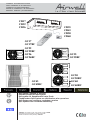 1
1
-
 2
2
-
 3
3
-
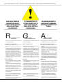 4
4
-
 5
5
-
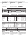 6
6
-
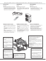 7
7
-
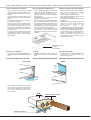 8
8
-
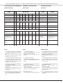 9
9
-
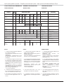 10
10
-
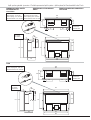 11
11
-
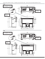 12
12
-
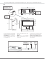 13
13
-
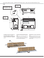 14
14
-
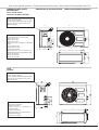 15
15
-
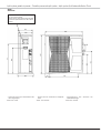 16
16
-
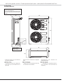 17
17
-
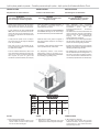 18
18
-
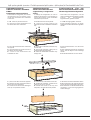 19
19
-
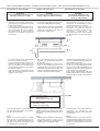 20
20
-
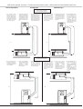 21
21
-
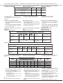 22
22
-
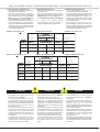 23
23
-
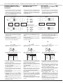 24
24
-
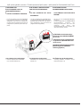 25
25
-
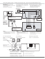 26
26
-
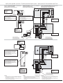 27
27
-
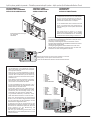 28
28
-
 29
29
-
 30
30
-
 31
31
-
 32
32


Airwell CD50 Installation and Maintenance Manual
- Kategorie
- Split-System-Klimaanlagen
- Typ
- Installation and Maintenance Manual
in anderen Sprachen
- English: Airwell CD50
- français: Airwell CD50
Andere Dokumente
-
TECHNIBEL KPSW 3 Installationsanleitung
-
Rowenta HA 340 Benutzerhandbuch
-
Waeco CoolMatic CD50, CRD50 Installationsanleitung
-
Primare CD22 Benutzerhandbuch
-
Fakir Airwell Bedienungsanleitung
-
Philips MCW770/22 Schnellstartanleitung
-
Atlantic DF DUOLIX Installationsanleitung
-
Carrier 40SMC036N Benutzerhandbuch
-
-
mundoclima MUPR-09-H6M Installationsanleitung