
La Clim, c'est Airwell
.
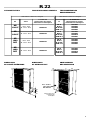
Multisplit system
Multisplit system
Multisplit-Bauweise
MS 1040 F/RCF
MS 1400 F/RCF
Gamme Confort • Comfort Range • Komfort Klimageräte
.
/*
,
NOTICE D'INSTALLATION TH3769 B - 3990066 / INSTALLATION INSTRUCTION / INSTALLATIONSHANDBUCH
Froid seul
Cooling Only
Nur Kühlung
Reversible
Heatpump
Wärmepumpe
MS 1040 F/RCF
MS 1400 F/RCF
SX 18
SX 24
K 18 A
K 24 A
GTW 18 F
GTW 24 F
4
4"%+

2
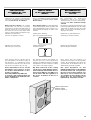
MISE HORS TENSION
OBLIGATOIRE AVANT
TOUTES INTERVENTIONS
DANS LES BOITIERS
ÉLECTRIQUES
RECOMMANDATIONS
GÉNÉRALES
Avant tout, merci d'avoir porté votre choix sur
un climatiseur Airwell.
CONSEILS DE SÉCURITÉ
Lorsque vous intervenez sur votre matériel,
suivez les règles de sécurité en vigueur.
L’installation et l’entretien du matériel devront
être effectués exclusivement par du personnel
qualifié.
Assurez-vous que l’alimentation électrique et
sa fréquence sont adaptées au courant de
fonctionnement nécessaire compte tenu des
conditions spécifiques de l’emplacement, et
du courant nécessaire à tout autre appareil bran-
ché sur le même circuit.
AVERTISSEMENT
Couper le courant avant toute intervention ou
opération d’entretien.
Le fabricant décline toute responsabilité et la ga-
rantie ne sera plus valable si ces instructions
d’installation ne sont pas respectées.
Si vous avez des difficultés, faites appel au
Service Technique de votre zone.
Avant la mise en place, procédez si possible au
montage des accessoires obligatoires ou non.
(Voir notice livrée avec chaque accessoire).
- Les informations contenues dans cette notice
sont sujettes à modifications sans préavis.
Cet appareil répond aux NORMES CE.
SWITCHING OFF POWER
SUPPLY IS MANDATORY
BEFORE ANY WORK
IN THE ELECTRIX BOXES
GENERAL
RECOMMENDATIONS
CongratulatIions on having selected an Airwell
air conditioner.
SAFETY HINTS
When you are working on your equipment, follow
the safety rules in force.
The installation and its maintenance should be
performed only by qualified professionals.
Make sure that the power supply and its
frequency are adapted to requirements, taking
into account the specific conditions in relation
to the location of the appliance and the power
required for any other equipment connected with
the same circuit.
WARNING
Switch off power supply before starting mainte-
nance of the appliance.
The manufacturer declines any responsibility and
the warranty will be void if these installation ins-
tructions are not followed.
If you meet difficulties, please call our
Technical Service in your area.
Before placing the appliance on its final loca-
tion, assemble if possible the accessories, if any.
(See instructions supplied with each accessory).
- The information contained in this document are
subject to modification without advance notice.
This appliance is in compliance with EEC stan-
dards.
ALLGEMEINE
EMPFEHLUNGEN
Zunächst ein Dankeschön dafür, daß Sie sich
für ein Airwell-Klimagerät entschieden haben!
SICHERHEITSREGELN
Bei Arbeiten an Ihrem Gerät befolgen Sie bitte
die geltenden Sicherheitsvorschriften.
Installation und Wartung sind ausschließlich dem
Fachmann vorbehalten.
Vergewissern Sie sich bitte, daß Netzspannung
und -frequenz den Anforderungen des Geräts
entsprechen. Dabei sind die spezifischen
Bedingungen am Aufstellungsort sowie ggf. der
Stromverbrauch weiterer an den gleichen
Stromkreis angeschlossener Geräte zu
berücksichtigen.
WICHTIGE HINWEISE
Vor Wartungs- oder sonstigen Arbeiten am Gerät
stellen Sie bitte die Stromzufuhr ab.
Bei Nichtbefolgung dieser Installationsanleitung
übernimmt der Hersteller keinerlei Haftung, und
die Garantie verfällt.
Bei Problemen wenden Sie sich bitte an den für
Sie zuständigen Kundendienst.
Zubehör (obligatorisch oder optional) sollte
möglichst vor der Installation des Geräts
eingebaut werden (siehe die mit den
verschiedenen Zubehörteilen gelieferte
Anleitung).
- Die in der vorliegenden Unterlage enthaltenen
Informationen können ohne Vorankündigung
geändert werden.
Dieses Gerät entspricht den CE Normen.
VOR ARBEITEN AM
SCHALTKASTEN MUSS
DAS GERÄT GRUNDSÄTZLICH
STROMFREI GEMACHT
WERDEN !

3
CE-PRÜFBESCHEINIGUNG
Erklärt hiermit, dass: die Kondensatoren der
Komfort-Baureihe MULTISPLIT SYSTEM den
nachstehend aufgeführten EG-Richtlinien und
der französischen Gesetzgebung über deren
Umsetzung entsprechen :
Maschinenrichtlinien 98 / 37 /CEE
Richtlinie EU 73/23 : Niederspannung
Richtlinie EU 89/336 : Elektromagnetische
Verträglichkeit (EMV)
und das
Es wurden folgende Teile der harmonisierten
Normen angewandt :
NF EN 60 204-1 / 1998
NF EN 60 335-1 / 1995
NF EN 60 335-2-40 / 1994
NF EN 55 022 / 1998
NF EN 61 000-3-2 / 1998
NF EN 50 082-1 / 1998
NF EN 814 / 1997
NF EN 378 / 1999
NF EN 255 / 1997.
DECLARATION CE
DE CONFORMITE
Déclare ci-après que : les unités de condensa-
tion de la gamme confort type MULTISPLIT
SYSTEM sont conformes aux dispositions des
directives CEE énoncées ci-après et aux légis-
lations nationales les transposant :
Directive Machines 98 / 37 /CEE
Directive Basse tension (DBT) 73/23/CEE
Directive compatibilité Electromagnétique
89/336/CEE
et que
les paragraphes suivants des normes harmo-
nisées ont été appliqués.
NF EN 60 204-1 / 1998
NF EN 60 335-1 / 1995
NF EN 60 335-2-40 / 1994
NF EN 55 022 / 1998
NF EN 61 000-3-2 / 1998
NF EN 50 082-1 / 1998
NF EN 814 / 1997
NF EN 378 / 1999
NF EN 255 / 1997.
EC STATEMENT
OF COMPLIANCE
Hereby states that : the air condensation sets in
the MULTISPLIT SYSTEM, models: are in
compliance with the provisions of the EEC di-
rectives mentioned hereunder and with the na-
tional legislation transposing them :
Machines Directive 98 / 37 /CEE
Low tension Directive (DBT) 73/23/EEC
Electromagnetic compatibility Directive
89/336/EEC
and that
the following paragraphs of the harmonized
standards have been applied :
NF EN 60 204-1 / 1998
NF EN 60 335-1 / 1995
NF EN 60 335-2-40 / 1994
NF EN 55 022 / 1998
NF EN 61 000-3-2 / 1998
NF EN 50 082-1 / 1998
NF EN 814 / 1997
NF EN 378 / 1999
NF EN 255 / 1997.

4
1 GC (unité extérieure)
1 Sachet documents, étiquettes de repères
1 Bon de garantie
1 Notice d'installation
2 Shunts pour couplage
en 230 V / 1N~ /50 Hz (MS 1040).
COMPOSITION DU COLIS CONTENTS OF PARCEL LIEFERUMFANG
SOMMAIRE
•N° produits finis .......................................... 5
•Dimensions de l'unité extérieure ............... 5
•Généralités.................................................. 6
•Installation de l'unité extérieure (MS) ........ 6
•Accessoire Bac condensats ...................... 7
•Accessoire Accrochage mural ................... 7
•Installation des unités intérieures (ST) ...... 7
•Raccordements frigorifiques...................... 8
•Liaisons frigorifiques .................................. 10
•Tirage au vide des tubes frigorifiques
et de l'unité intérieure ................................. 11
•Particularités du modèle MS 1400
réversible .................................................... 12
•Raccordements électriques entre
les unités extérieures et intérieures ........... 13
•Spécifications électriques .......................... 14
•Connection électrique ................................ 15
•Raccordements électriques
MS 1040 F/RCF
- vers SX 18 ou K 18 A
avec ou sans chauf. élec. ........................ 16
- vers GTW 18 F
avec ou sans chauf. élec. ........................ 17
MS 1400 F/RCF
- vers SX 24
avec ou sans chauf. élec.mono. ............. 18
ou K 24 A
avec ou sans chauf. élec.. ....................... 18
- vers SX 24
avec chauf. élec. 3N~400V ..................... 19
- vers GTW 24 F
avec ou sans chauf. élec. ........................ 20
•Taches finales ............................................. 21
•Maintenance ............................................... 22
SUMMARY
•Finished products numbers ....................... 5
•Dimensions of outdoor units ...................... 5
•General ........................................................ 6
•Installing the outdoor unit ........................... 6
•Accessory condensat tray .......................... 7
•Accessory wall-mounting bracket .............. 7
•Installing the indoor units ........................... 7
•Refrigerant connections ............................. 8
•Refrigerant lines .......................................... 10
•Vacuum of cooling pipes
and indoor unit ............................................ 11
•Specific points of MS 1400
heatpump models ....................................... 12
•Electrical connection between
outdoor and indoor unit .............................. 13
•Electric specifications ................................ 14
•Electrical connections ................................ 15
•Electric connections
MS 1040 F/RCF
> SX 18 or K 18 A
with or without electric heating ............... 16
> GTW 18 F
with or without electric heating .............. 17
MS 1400 F/RCF
> SX 24
with or without electric heating .............. 18
or K 24 A
with or without electric heating .............. 18
> SX 24
with electric heating ............................... 19
> GTW 24 F
with or without electric heating .............. 20
•Final steps ................................................... 21
•Servicing ..................................................... 22
INHALT
•Teilnummern der Enderzeugnisse ............. 5
•Abmessungen der Außenteile ................... 5
•Allgemeines ................................................ 6
•Montage des Aussenteils (GC) .................. 6
•Zubehör kondensationwasserwanne ........ 7
•Zubehör Wandbefestigung ........................ 7
•Montage der Innenteile (ST) ...................... 7
•Kältetechnische Anschlüsse ...................... 8
•Kältemittelverbindungsleitungen ............... 10
•Entleeren der Kältemitteleitungen
und des Innenteils ...................................... 11
•Besonderheiten bei Wp-Modellen
MS 1400 ...........................................12
•Elektrischer Anschluss zwischen
aussen- und innenteil ................................. 13
•Elektrische spezifikationen ........................ 14
•Stromanschlüsse ........................................ 15
•Elektrische anschlüsse
MS 1040 F/RCF
> SX 18 oder K 18 A
mit oder ohne elektroheizung................ 16
> GTW 18 F
mit oder ohne elektroheizung................ 17
MS 1400 F/RCF
> SX 24
mit oder ohne elektroheizung................. 18
oder K 24 A
mit oder ohne elektroheizung................ 18
> SX 24
mit elektroheizung .................................. 19
> GTW 24 F
mit oder ohne elektroheizung................ 20
•Abschliessende arbeiten............................ 21
•Wartung ...................................................... 22
1 GC (Outdoor unit)
1 Packet containing documents, marking
labels
1 Warranty voucher
1 Installation guide
2 Shunts for connection to 230 VAC, single
phase, 50 Hz (MS 1040).
1 GC (Außenteil)
1 Tüte mit Unterlagen und
Kennzeichnungsetiketten
1 Garantieschein
1 Montageanleitung
2 Brücken für die Umschaltung auf 230 V /
1N~ /50 Hz (MS 1040).

5
Froid seul
Cooling only
Nur Kühlung
Réversible
Heatpump
Wärmepumpe
Unité extérieure / Outdoo unit / Innengerät Unités intérieure / Indoor unit / Außengerät
GC Tension
N° Produits finis
Finished product part numbers
Teilenummern der enderzeugnisse
ST
N° Produits finis
Finished product part numbers
Teilenummern der enderzeugnisse
MS
1040 F
~230 V - 50 Hz
3N ~400 V - 50 Hz
7SP091060B
SX 18
K 18 A
K 18 ACF
GTW 18 F
7SP012004
7SP042004
7SP042009
7SP033005
MS
1400 F
3N ~400 V - 50 Hz 7SP091058B
SX 24
K 24 A
K 24 ACF
GTW 24 F
7SP012005
7SP042005
7SP042010
7SP033007
MS
1040
RCF
~230 V - 50 Hz
3N ~400 V - 50 Hz
7SP091061B
SX 18
K 18 A
K 18 ACF
GTW 18 F
7SP012004
7SP042004
7SP042009
7SP033005
MS
1400
RCF
3N ~400 V - 50 Hz 7SP091059B
SX 24
K 24 A
K 24 ACF
GTW 24 F
7SP012005
7SP042005
7SP042010
7SP033007
TEILENUMMERN DER
ENDERZEUGNISSE
N° PRODUITS FINIS FINISHED PRODUCT NUMBERS
4"%+
ABMESSUNGEN
DER AUßENTEILE
DIMENSIONS
DE L'UNITÉ EXTÉRIEURE
DIMENSIONS
OF OUTDOOR UNIT
120
65,4
75
65,4
1120
9
5
5
3
37
1115
Face arrière
Rear panel
Rückwand
Grille de protection
Protection grill
Schutzgitter

6
TEILENUMMERN DER
ENDERZEUGNISSE
N° PRODUITS FINIS FINISHED PRODUCT NUMBERS
Unité extérieure / Outdoo unit / Innengerät Unités intérieure / Indoor unit / Außengerät
GC Tension
N° Produits finis
Finished product part numbers
Teilenummern der enderzeugnisse
ST
N° Produits finis
Finished product part numbers
Teilenummern der enderzeugnisse
MS
1040 F
~230 V - 50 Hz
3N ~400 V - 50 Hz
7SP091012A
SX 18
K 18 A
K 18 ACF
GTW 18 F
7SP012004
7SP042004
7SP042009
7SP033005
MS
1400 F
3N ~400 V - 50 Hz 7SP091014B
SX 24
K 24 A
K 24 ACF
GTW 24 F
7SP012005
7SP042005
7SP042010
7SP033007
MS
1040
RCF
~230 V - 50 Hz
3N ~400 V - 50 Hz
7SP091013A
SX 18
K 18 A
K 18 ACF
GTW 18 F
7SP012004
7SP042004
7SP042009
7SP033005
MS
1400
RCF
3N ~400 V - 50 Hz 7SP091017B
SX 24
K 24 A
K 24 ACF
GTW 24 F
7SP012005
7SP042005
7SP042010
7SP033007
4
ABMESSUNGEN
DER AUßENTEILE
DIMENSIONS
DE L'UNITÉ EXTÉRIEURE
DIMENSIONS
OF OUTDOOR UNIT
120
65,4
75
65,4
1120
95
5
3
3
7
1115
Face arrière
Rear panel
Rückwand
Grille de protection
Protection grill
Schutzgitter

7
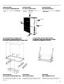
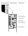
GÉNÉRALITÉS
L'unité extérieure (GC) est composée de :
•2 voies bi-compresseur :
2 compresseurs è 2 circuits indépendants.
Les étiquettes fournies permettent de repérer
les circuits frigorifiques au fur et à mesure de
l'installation :
A = Ligne "LIQUIDE"
B = Ligne "GAZ"
1 = Circuit 1 (groupe bas)
2 = Circuit 2 (groupe haut).
INSTALLATION
DE L'UNITÉ EXTÉRIEURE (GC)
Dégagement min. à prévoir (en mm)
voir page 7.
Respectez les côtes afin d'éviter le recyclage
de l'air même partiel entre l'aspiration et le souf-
flage de l'air.
Fixation au sol :
Le GC froid seul est prévu pour être fixé
directement au sol.
Le GC réversible est doté d'un orifice dans
le fond de l'appareil, pour permettre l'évacua-
tion de l'eau produite au moment du dégivrage;
de ce fait, le GC ne doit pas être posé directe-
ment au sol mais surélevé.
L'accessoire "bac de condensats" est prévu
à cet effet (voir notice fournie avec l'accessoire)
kit N° 687007-88.
Accrochage mural :
Le GC peut être accroché au mur à l'aide d'une
chaise fournie en kit N° 687048-88 (voir page
7).
Schéma des différentes
combinaisons avec les unités
intérieures :
58
25
25
268
218
58
980
GENERAL
The outdoor unit includes :
•2 two-compressor channels
2 compressors with 2 separate systems.
The labels supplied allow the refrigerant lines to
be marked as installation proceeds :
A = LIQUID line
B = GAS line
1 = System 1 (bottom unit)
2 = System 2 (top unit)
INSTALLING
THE OUTDOOR UNIT
Min clearance to be provided (in mm)
See page 7
Comply with the specified dimensions to prevent
even partial recirculation of the air between
suction and discharge.
Floor-Mounting :
The cooling-only outdoor unit is designed
to be mounted directly on the floor.
The heatpump outdoor unit includes a port
in the bottom to allow drainage of the water
produced during deicing,.the outdoor unit
must therefore be raised off the floor.
The condensate tray is provided for this
purpose (refer to the instructions provided with
the accessory) kit P/N 687007-88.
Wall Mounting :
The outdoor unit can be mounted on the wall
using a bracket, available in kit-P/N 687048-
88 (see page 7).
Diagram of the different
combinations with indoor
units :
ALLGEMEINES
Das Außenteil (GC) besteht aus :
•2 Doppelkompressorkanälen
2 Kompressoren ? 2 unabhängige Kreisläufe.
Die mitgelieferten Etiketten dienen zur
Kennzeichnung der Kühlkreise im Verlauf der
Montage :
A = "FLÜSSIGKEITS“-Leitung
B = "GAS“-Leitung
1 = Kreis 1 (unteres Aggregat)
2 = Kreis 2 (oberes Aggregat)
MONTAGE
DES AUSSENTEILS (GC)
Mindestabmessung des vorzusehen-
den Freiraums (in mm)
Siehe Seite 7.
Die Maßangaben einhalten, um zu vermeiden,
dass die Luft, sei es auch teilweise, zwischen
dem Ansaugen und dem Ausschub umläuft.
Bodenbefestigung:
Nur die Kühlvorrichtung kann unmittelbar auf
dem Boden befestigt werden.
Der Boden des umkehrbaren Außenteils ist mit
einer Öffnung versehen, damit das beim
Abtauen erzeugte Wasser abgeleitet werden
kann. Deshalb ist das Außenteil nicht direkt auf
dem Boden sondern erhöht zu montieren.
Das Zubehör „Kondenswasserwanne“ ist zu
diesem Zweck vorgesehen (siehe dem Zubehör
beiliegende Anleitung). Bausatz Nr. 687007-88.
Wandbefestigung:
Das Außenteil kann mit Hilfe der dem Bausatz
Nr. 687048-88 beiliegenden Konsole an der
Wand befestigt werden (siehe Seite 7)
Plan der verschiedenen
Kombinationsmöglichkeiten
mit den Innenteilen :
MS 1040 F
MS 1040 RCF
MS 1400 F
MS 1400 RCF
B2
B2
B1
B1
A2
A2
A1
A1
GTW18F
GTW24F
GTW24F
GTW18F
K18A
K24A
K24A
K18A
SX 18
SX 24
SX 24
SX 18
ou
or
oder
ou
or
oder
ou
or
oder
ou
or
oder

8
INSTALLATION
DE L'UNITÉ EXTÉRIEURE MS
•Rappel des dégagements MINIMUM à
prévoir :
INSTALLATION
DER AUßENEINHEIT
•Angabe der vorgeschriebenen MINDEST-
FREIRÄUME :
INSTALLATION
OF THE OUTDOOR UNIT
•Reminder of MINIMUM clearances to be
provided :
ACCESSOIRE BAC CONDENSATS
ACCESSORY CONDENSATE TRAY
ZUBEHÓR KONDENSATIONWASSERWANNE
150 mm
150 mm
500 mm
400 mm
100 mm
ACCESSOIRE ACCROCHAGE MURAL
ACCESSORY WALL-MOUNTING BRACKET
ZUBEHÓR WANDBEFESTIGUNG
INSTALLATION
DES UNITÉS INTÉRIEURES (ST)
Pour la mise en place des ST se reporter à
la notice d'installation fournie avec ces unités
intérieures.
INSTALLING
THE INDOOR UNITS
For installation of the indoor units, refer to the
installation guide supplied with the indoor units.
MONTAGE
DER INNENTEILE (ST)
Zur Montage der ST die diesen Einheiten
beiliegende Montageanleitung befolgen.

9
3m
3m
3m
3m
RACCORDEMENTS
FRIGORIFIQUES
REFRIGERANT
CONNECTIONS
KÄLTETECHNISCHE
ANSCHLÜSSE
MS 1040 F/1040 RCF
MS 1400 F/1400 RCF
Tube LIQUIDE / LIQUID pipe / Flüssigkeitsleitung
Tube GAZ / GAS pipe / Saugleitung
SX 18 / K 18 A / GTW 18 F
A2
B2
A1
B1
Tube LIQUIDE / LIQUID pipe / Flüssigkeitsleitung
Tube GAZ / GAS pipe / Saugleitung
SX 18 / K 18 A / GTW 18 F
Tube LIQUIDE / LIQUID pipe / Flüssigkeitsleitung
Tube GAZ / GAS pipe / Saugleitung
SX 24 / K 24 A / GTW 24 F
A2
B2
A1
B1
Tube LIQUIDE / LIQUID pipe / Flüssigkeitsleitung
Tube GAZ / GAS pipe / Saugleitung
SX 24 / K 24 A / GTW 24 F
Modèles froid seul
Dans le cas où le tube d'aspiration a une partie
verticale excédant 8 m, il est IMPERATIF de pro-
céder à la réalisation d'un siphon tous les 3 m
lorsque le Groupe de Condensation est installé
au-dessus du Caisson de Traitement.
Cooling only models
If the suction tube has a vertical section more
than 8 m in length, it is mandatory to provide a
siphon every three meters when the condensor
unit is installed above the processing unit (inter-
connecting tubes with a bottle).
Linking pipes 9 to 25 m
9 < B < 15 m trap every 3 m
Liaison 9 à 25 m
9 < B < 15 m siphon tous les 3 m
Placer un siphon sur la ligne GAZ tous les 3 m.
Fil a siphon on the Gas line every 3 m.
Muß in die Gasleitung im Abstand von jeweils 3
m ein Siphon angebracht werden.
H = 15 m maxi.
Nur Kühlung
Sollte die Ansaugleitung einen senkrechten Teil
von mehr als 8 m aufweisen, MUSS alle 3 m ein
Siphon angebracht werden, wenn die
Verflüssigereinheit oberhalb des Aufbereitungs-
kastens angeordnet ist.
Leitung 9 bis 25 m
9 < B < 15 m Siphon alle 3 m

10
C
D
D
D
A
B
A
C
C
C
C
E
E
E
E
D
B
Tube « Gaz »
Tube « Liquide »
Écrou Flare
Isolation des tubes (6 mm minimum)
Manchon isolant
«Gaz» pipe
«Liquid» pipe
Flare nut
Pipe insulation (6 mm min.)
Insulation sleeve
A
B
C
D
E
A
B
C
D
E
Saugleitung
Flüssigkeitsleitung
Bördelmutter
Leitungsisolierung (6 mm min)
Isoliermuffe
A
B
C
D
E
RACCORDEMENTS
FRIGORIFIQUES
REFRIGERANT
CONNECTIONS
KÄLTETECHNISCHE
ANSCHLÜSSE
- L'unité intérieure peut-être installée
indefféremment au dessus ou au dessous de
l'unité.
- Les liaisons FLARE sont disponibles en acces-
soire, en longueurs fixes : 2,5 - 5 - 8 m.
- Les tubes sont livrés enroulés et équipés
d'écrous FLARE.
- Dérouler soigneusement les tubes dans le
sens inverse des spires afin de ne pas les plier.
- The indoor unit may be installed above or below
the unit
- The flare couplings are available as
accessories in standard lengths of 2.5, 5 and
8 m.
- The pipes are delivered coiled and equipped
with flare nuts.
- Carefully uncoil the pipes in the opposite di-
rection from the turns so as not to flatten them.
- Das Innenteil kann oberhalb wie auch
unterhalb des Gerätes installiert werden.
- Die FLARE Verbindungen sind als Zubehör in
festen Längen erhältlich: 2,5 - 5 - 8 m.
- Die Rohre werden aufgewickelt und mit FLARE
Muttern versehen geliefert.
- Die Rohre in entgegengesetzter Richtung der
Windungen sorgfältig abwickeln, damit sie
nicht knicken.
L max.
MS 1040 F
25 m
MS 1040 RCF
25 m
MS 1400 F
25 m
MS 1400 RCF
15 m
MS
SX K GTW
SX K GTW
ou
or
oder
ou
or
oder
R > 3,5 Ø
R
Ø
Cintrage des tubes frigorifiques Bending of cooling pipes Krümmung der
Kältemittelleitungen

11
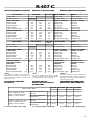
Caractéristiques MS 1040 MS 1400
Characteristics
Merkmale
Tube gaz isolé Ø Tube 5/8" 5/8" Tube Ø Insaluted gas tube Ø Rohr Isolier tes Gaslrohr
Tube liquide isolé Ø Tube 3/8" 3/8" Tube Ø Insaluted liquid pipe Ø Rohr Isoliertes Flüssigkeitsrohr
Charge dans le groupe
extérieur
(charge introduite en usine)
pour 4 m
GC froid
seul
1150 g 1580 g
cooling
only GC
Charge in outside unit
(factory charged)
for in 4 m
nur kalt
GC
Füllung im
Außenaggregat
(werksseitig gefüllt)
für 4 m
GC
réversible
1280 g 1815 g
heatpump
GC
Umkehrbares
GC
SX 18 K 18 A GTW 18F GTW 24 F K 24 A SX 24
Charge R-407C
à ajouter sur
chantier
MS 1040 0+10 g+90 g
R-407C
charge
to be added on
site
Füllung R-407C von
Ort hinzufügen
MS 1400
0 + 80 g + 90 g
TABLEAU A TABLE A TABELLE A
LIAISONS FRIGORIFIQUES
Charge en R-407C des MS.
KÄLTEMITTELVERBINDUNGS-
LEITUNGEN
Füllung der MS mit R-407C.
REFRIGERANT LINES
Charge in R-407C of MS.
TABLEAU C
Charge en R-407C en fonction de la longueur
des liaisons frigorifiques.
La charge en R-407C est contenue uniquement
dans le caisson extérieur. L'unité intérieure con-
tient une petite quantité de gaz neutre. C'est
pourquoi après avoir installer les liaisons, il faut
impérativement tirer au vide les liaisons et l'unité
intérieure (voir Notice d'Installation).
SX / K / GTW
(grs)
SX / K / GTW
(grs)
SX / K / GTW
(grs)
SX / K / GTW
(grs)
Longueurs des liaisons
Length of connections
Länge der Leitungen
5 m 17 11 m 119 16 m 204 22 m 306
6 m 34 12 m 136 17 m 221 23 m 323
7 m 51 13 m 153 18 m 238 24 m 340
8 m 68 14 m 170 19 m 255 25 m 357
9 m 85 14 m 170 20 m 272
10 m 102 15 m 187 21 m 289
TABLE C
R-407C charge based on the length of the
refrigerant lines.
The R-407C charge is contained entirely in the
outdoor unit. The indoor unit contains a small
amount of neutral gas. That is why it is absolutely
necessary to create a vacuum in the lines and
the indoor unit after installing the lines (see Ins-
tallation Instructions).
TABELLE C
R-407C-Befüllung unter Berücksichtigung der
Länge der Kältemittelverbindungsleitungen.
DieR-407C-Befüllung befindet sich
ausschließlich in der äußeren Einheit. Das
Innenteil beinhaltet eine kleine Menge
Neutralgas. Deshalb müssen nach der Montage
der Verbindungsleitungen diese Leitungen und
das Innenteil evakuiert werden (siehe
Montageanleitung).
Exemples :
(valable uniquement pour une installation Flare)
•Installation d'un SX 18 avec 15 m de liaisons
frigorifiques sur le groupe 1 : Tableau B +
Tableau C = ajouter 0g + 187g de R-407C
sur chantier.
•Installation d'une K 18A avec 10 m de liaisons
frigorifiques sur le groupe 2 :
Tableau B + Tableau C = ajouter 80g + 102g=
182g deR-407C sur chantier.
Examples :
(applies only to a flare pipe installation)
•Installation of an SX 18 with 15 m of refrigerant
lines on unit 1 : Table B + Table C = Add 0g +
187g of R-407C on site.
•Installation of a K 18A with 10 m of refrigerant
lines on unit 2 :
Table B + Table C = Add 80g + 102g = 182 g
of R-407C on site.
Beispiel :
(gilt ausschließlich für Flare-Anlagen)
•Montage eines SX 18 mit 15 m
Kältemittelverbindungsleitungen am Aggregat
1 : Tabelle B + Tabelle C = 0 g + 187 g R-
407C auf der Baustelle hinzufügen.
•Montage einer K 18A mit 10 m Kältemittel-
verbindungsleitungen am Aggregat 2 :
Tabelle B + Tabelle X = 80 g + 102 g = 182 g
R-407C auf der Baustelle hinzufügen.
TABLEAU B TABLE B TABELLE B
Ajout de charge en R-407C en fonction des uni-
tés intérieures.
R-407C charge to be added in relation to
number of indoor units.
Nachfüllung mit R-407C entsprechend den
Innenein-heiten.
4"%+

12
LIAISONS FRIGORIFIQUES
Charge en R-22 des MS.
KÄLTEMITTELVERBINDUNGS-
LEITUNGEN
Füllung der MS mit R-22.
REFRIGERANT LINES
Charge in R-22 of MS.
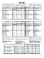
Caractéristiques MS 1040 MS 1400
Characteristics
Merkmale
Tube gaz isolé Ø Tube 5/8" 5/8" Tube Ø Insaluted gas tube Ø Rohr Isoliertes Gaslrohr
Tube liquide isolé Ø Tube 3/8" 3/8" Tube Ø Insaluted liquid pipe Ø Rohr Isoliertes Flüssigkeitsrohr
Charge dans le groupe extérieur
(charge introduite en usine)
pour 4 m
GC froid
seul
1126 g 1650 g
cooling
only GC
Charge in outside unit
(factory charged)
for in 4 m
nur kalt
GC
Füllung im Außenaggregat
(werksseitig gefüllt)
für 4 m
GC
réversible
1180 g 1710 g
heatpump
GC
Umkehrbares
GC
TABLEAU C
Charge en R-22 en fonction de la longueur
des liaisons frigorifiques.
La charge en R-22 est contenue uniquement
dans le caisson extérieur. L'unité intérieure con-
tient une petite quantité de gaz neutre. C'est
pourquoi après avoir installer les liaisons, il faut
impérativement tirer au vide les liaisons et l'unité
intérieure (voir Notice d'Installation).
SX / K / GTW
(grs)
SX / K / GTW
(grs)
SX / K / GTW
(grs)
SX / K / GTW
(grs)
Longueurs des liaisons
Length of connections
Länge der Leitungen
5 m 17 11 m 119 16 m 204 22 m 306
6 m 34 12 m 136 17 m 221 23 m 323
7 m 51 13 m 153 18 m 238 24 m 340
8 m 68 14 m 170 19 m 255 25 m 357
9 m 85 14 m 170 20 m 272
10 m 102 15 m 187 21 m 289
TABLE C
R-22 charge based on the length of the
refrigerant lines.
The R-22 charge is contained entirely in the
outdoor unit. The indoor unit contains a small
amount of neutral gas. That is why it is absolutely
necessary to create a vacuum in the lines and
the indoor unit after installing the lines (see Ins-
tallation Instructions).
TABELLE C
R-22-Befüllung unter Berücksichtigung der
Länge der Kältemittelverbindungsleitungen.
DieR-22-Befüllung befindet sich ausschließlich
in der äußeren Einheit. Das Innenteil beinhaltet
eine kleine Menge Neutralgas. Deshalb müssen
nach der Montage der Verbindungsleitungen
diese Leitungen und das Innenteil evakuiert
werden (siehe Montageanleitung).
Exemples :
(valable uniquement pour une installation Flare)
•Installation d'un SX 18 avec 15 m de liaisons
frigorifiques sur le groupe 1 : Tableau B +
Tableau C = ajouter 85g + 187g de R-22
= 272g.
•Installation d'une K 18A avec 10 m de liaisons
frigorifiques sur le groupe 2 :
Tableau B + Tableau C = ajouter 0g + 102g=
182g deR-22 sur chantier.
Examples :
(applies only to a flare pipe installation)
•Installation of an SX 18 with 15 m of refrigerant
lines on unit 1 : Table B + Table C = Add 85g
+ 187g of R-22 = 272g.
•Installation of a K 18A with 10 m of refrigerant
lines on unit 2 :
Table B + Table C = Add 80g + 102g = 182 g
of R-22 on site.
Beispiel :
(gilt ausschließlich für Flare-Anlagen)
•Montage eines SX 18 mit 15 m
Kältemittelverbindungsleitungen am Aggregat
1 : Tabelle B + Tabelle C = 85 g + 187 g R-
22 auf der Baustelle hinzufügen= 272g.
•Montage einer K 18A mit 10 m Kältemittel-
verbindungsleitungen am Aggregat 2 :
Tabelle B + Tabelle X = 80 g + 102 g = 182 g
R-22 auf der Baustelle hinzufügen.
TABLEAU B TABLE B TABELLE B
Ajout de charge en R-22 en fonction des uni-
tés intérieures.
R-22 charge to be added in relation to number
of indoor units.
Nachfüllung mit R-22 entsprechend den
Innenein-heiten.
4
SX 18 K 18 A GTW 18F GTW 24 F K 24 A SX 24
Charge R-22 à
ajouter sur chantier
MS F 85 0 g +95 g +140g +60g 0g
R-22
charge to be
added on site
Füllung R-22 von Ort
hinzufügen
MS RCF +70G +0G +65G +110g +100g 0 g

13
TIRAGE AU VIDE
DES TUBES FRIGORIFIQUES
ET DE L'UNITÉ INTÉRIEURE
- La charge en fluide réfrigérant est contenue
uni-quement dans le caisson extérieur. L'unité
intérieure contient une petite quantité de gaz
neutre. C'est pourquoi après avoir installé les
liaisons, il faut impérativement tirer au vide
les liaisons et l'unité intérieure.
PROCÉDURE DE MONTAGE
- Le groupe extérieur possède une vanne
permettant le tirage au vide de l'installation
(grosse vanne) :
1 Connecter les tubes de liaison au caisson
extérieur et à l'unité intérieure.
• Pour obtenir un bon serrage, recouvrir la
surface avec de l'huile de réfrigération.
• L'utilisation d'une contre clef est indispen-
sable pour le serrage des vannes.
• Les valeurs du couple de serrage se trou-
vent dans le tableau ci-dessous :
2 Connecter la pompe à vide au raccord flare
du caisson extérieur muni de la vanne de
service.
3 Mettre la pompe à vide en marche et véri-
fier que l'aiguille de l'indicateur descend à
- 0,2 mm Hg.
La pompe doit fonctionner pendant
15 minutes au minimum.
4 Avant de retirer la pompe à vide, il faut
vérifier que l'indicateur de vide reste stable
pendant 5 minutes.
5 Déconnecter la pompe à vide et refermer la
vanne de service.
6 Enlever le bouchon de la vanne "GAZ" et
"LIQUIDE" et les ouvrir à l'aide d'une clé
hexagonale afin de libérer le fluide réfrigé
rant contenu dans le groupe extérieur.
7 Dans le cas où la liaison frigorifique d'une
voie est supérieure à 4m, procéder à un
complément de charge suivant le tableau
C- voir page 10.
Certaines unités nécessitent un ajout de
charge suivant le tableau B - voir page 10.
8 Vérifier l'étanchéité des liaisons. Utiliser un
détecteur de fuite électronique ou une
éponge savonneuse.
VACUUM OF COOLING PIPES
AND INDOOR UNIT
- Only the outdoor unit is charged with cooling
fluid. The indoor unit contains a small quantity
of a neutral gas. This the reason it is imperative
to vacuum the linking pipes and the indoor
unit.
ASSEMBLY
- The outdoor unit is equipped with a valve
allowing to vacuum the installation (large valve)
1 Connect the connecting pipes to the outdoor
unit by FLARE NUTS and to the indoor unit
by BRAZING
- To obtain the right tightening, cover the
surface with cooling oil.
- The use of a counter wrench is required
to tighten the valves.
- The values of the tightening torque are
shown in the table below.
2 Connect the vacuum pump with the flare
coupling of the outdoor unit equipped with
a process valve.
3 Start the vacuum pump and check that the
needle of the indicator goes down to
- 0,2 mm Hg.
The pump should run during at least
15 minutes.
4 Before disconnecting the vacuum pump,
check that the vacuum indicator remains in
the same position during five minutes.
5 Disconnect the vacuum pump and close the
service valve.
6 Remove the cap of the "GAS" and "LIQUID"
valves and open them with a hexagonal
wrench to free the contained in
the outdoor unit.
7 If the refrigerant line of a system is more than
4 m long, add extra charge as per table C -
see page 10.
Certain units require an additional charge as
per table B - see page 10.
8 Check that the linking pipes are sealed. Use
an electronic leak detector or a soapy
sponge.
ENTLEEREN DER
KÄLTEMITTELLEITUNGEN
UND DES INNENTEILS
- Nur das Außenteil ist mit geladen. Das Innenteil
enthält eine kleine Menge Neutralgas. Daher
müssen nach Installieren der Verbindungen
diese, sowie das Innenteil, unbedingt entleert
werden.
MONTAGE
- Das Außenteil verfügt über ein Ventil zum
Entleeren der Anlage (großes Ventil)
1Die Verbindungsleitungen an die Außenteile
MIT BÖRDELMUTTERN und an die Innenteile
DURCH LÖTUNG anschließen.
- Um einen festen Sitz zu gewährleisten, die
Oberfläche mit Kühlöl behandeln.
- Zum Anziehen der Ventile ist ein
Gegenschlüssel unerläßlich.
- Die Anziehdrehmomente sind in
nachstehender Tabelle angegeben:
2 Die Vakuumpumpe mit der Kupplung des
Außenteils verbinden, das mit dem
Betriebsventil versehen ist.
3 Die Vakuumpumpe in Betrieb setzen und
prüfen, daß die Anzeigernadel auf -0,2mm
Hg.Die Pumpe muß mindestens 15
Minuten arbeiten.
4 Bevor die Vakuumpumpe wieder entfernt
wird, prüfen, daß der Unterdruckmesser
5 Minuten lang unverändert bleibt.
5 Die Vakuumpumpe abklemmen und das
Schraderventil schließen.
6 Den Stopfen des «GAS» und
«FLÜSSIGKEITS» -Ventils entfernen und die
Ventile mit einem Sechskantschlüssel
öffnen, um das in dem Außenteil befindliche
freizusetzen.
7 Sollte die Länge der Einweg Kältemittelver-
bindungsleitung 4 m überschreiten, die
Befüllung gemäß Tabelle C ergänzen – siehe
Seite 10.
Die Befüllung bestimmter Einheiten muss
gemäß Tabelle B ergänzt werden – siehe
Seite 10.
8 Die Verbindungen auf Dichtigkeit prüfen.
Dazu einen elektronischen Lecksucher oder
einen Seifenschwamm verwenden.
Ø des tubes /Ø of the Pipe
Ø Rohrdurchmesses
Couple / Torque
Anzugsdrehmoment
Tube / Pipe / Rohr 1/4"
Tube / Pipe / Rohr 3/8"
Tube / Pipe / Rohr 1/2"
Tube / Pipe / Rohr 5/8"
Tube / Pipe / Rohr 7/8"
15-20 Nm
30-35 Nm
50-54 Nm
70-75 Nm
90-95 Nm

14
PARTICULARITÉS
DU MODÈLE MS 1400
RÉVERSIBLE
- L'utilisation du capillaire supplémentaire
(repéré par une étiquette rouge) est vraiment
nécessaire au-dessus de 8 mètres.
- En dessous de 8 mètres, elle est plutôt
préjudiciable à la puissance calorifique
(marche hiver) et à une bonne température de
l'huile du compresseur ; il n'est donc pas utile
de le laisser en service. C'est pourquoi il faut
le pincer comme indiqué sur l'étiquette rouge.
- Capillaire avant pincement :
(la boucle est préparée en usine).
- Capillaire après pincement :
Utiliser une pince à bec plat.
- Cette opération doit être effectuée par un
personnel qualifié et en suivant les règles de
l'art du frigoriste. Le complément de charge
s'effectue par la vanne de service du raccord
flare du caisson extérieur (gros raccord).
- Toutes interventions sur les circuits
frigorifiques nécessitent le respect
des normes internationales et euro-
péennes en vigueur :
ISO 5149-pr EN378-4-pr EN13313
et en France aux réglementations du
décret du 30/06/98 sur l'utilisation des
fluides réfrigérants.
SPECIFIC POINTS
OF MS 1400 HEATPUMP
MODELS
- The use of the additional capillary (marked with
a red label) is only needed at a length of more
than 8 meters.
- If less than 8 meters it is rather detrimental
to the heating capacity (winter operation) and
to the right temperature of the compressor oil;
therefore pinch the capillary as shown on the
red label.
- Capillary before pinching :
(the loop is prepared at the factory).
- Capillary after pinching :
Use flat-nose pliers.
- This operation should be done expertly by
qualified personnel and (regrigeration
engineer). The additional charge is to be added
through the process valve of the flare coupling
of the outdooor unit (large coupling).
- Any work carried out on the cooling
circuits must comply with the interna-
tional and European standards in force
ISO5149-prEN378-4-prEN13313
and in France with the regulations of
the decree of 30/06/98 on the use of
coolants.
BESONDERHEITEN
BEI WP-MODELLEN
MS 1400
- Die Verwendung des zusätzlichen
Kapillarrohrs (durch ein rotes Etikett
gekennzeichnet) ist nur bei Verbindungs-
leitungen von über 8 Metern Länge
sinnvoll.
- Bei kürzeren Leitungen beeinträchtigt es die
Heizleistung (Winterbetrieb) und die richtige
Temperatur des Kompressorenöls und sollte
daher - wie auf dem roten Etikett gezeigt -
abgequetscht werden.
- Kapillarrohr vor dem Abquetschen :
(werkseitig vorbereitete Schleife).
- Kapillarrohr nach Klemmung :
Eine Flachzange verwenden.
- Diese Arbeit darf ausschließlich von
qualifiziertem Fachpersonal durchgeführt
werden. Die Zusatzfüllung wird durch das
Schraderventil des Bördelanschlusses der
Außeneinheit (großer Ø) eingeführt.
- Bei allen Eingriffen an den
Kältekreisläufen müssen die gültigen
internationalen und europäischen
Normen (ISO 5149-pr EN378-4-pr
EN13313) und in Frankreich die
Vorschriften der Verordnung vom 30/
06/98 über die Verwendung von
Kältemitteln eingehalten werden.
Capillaire supplémentaire
Additional capillary
Zusätzliches Kapillarrohr

15
A2
B2
A1
B1
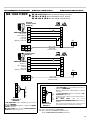
RACCORDEMENTS ÉLECTRIQUES
ENTRE LE GC ET LES ST
Ne pas tenir compte du raccordement électri-
que dans la notice des ST.
Sur le GC ôter le panneau de façade M.
A EFFECTUER HORS TENSIONS TO BE CARRIED OUT WITH THE
ELECTRICAL SYSTEM DE-ENERGISED
BEI SPANNUNGSFREIER ANLAGE ARBEITEN
ELECTRICAL CONNECTION
BETWEEN OUTDOOR AND
INDOOR UNIT
Ignore the electrical connection instructions in
the indoor unit manual.
Remove front panel M from the outdoor unit.
L'alimentation générale
s'effectue sur le GC :
- Câble d'alimentation hors fournitures (se
reporter au spécifications électriques page
14).
- Passer le câble dans le presse étoupe (rep.
C) et se connecter sur le bornier X (voir page
15).
Spécifications électriques
pour câble de liaisons
(Câble de liaison ST hors fourniture).
- Se reporter aux spécifications électriques (voir
page 14).
- Passer les câbles dans les presses étoupes
(rep. C1 et C2).
- Raccordement sur bornier X1 (groupe 1) et
X2 (groupe 2).
(N'utiliser qu'un seul câble multiconducteur
pour effectuer la liaison entre chaque ST et
GC).
(Valeurs données à titre indicatif, se reporter aux
normes en vigueur sur le site).
NOTA :
- Les fils reliés aux bornes 8 et 9 (fils de
sondes) doivent se trouver dans un câble
séparé, sinon les commandes électroniques
peuvent être sujettes à des défaillances de
fonctionnement.
- Des étiquettes sont fournies avec l'unité exté-
rieure afin de repérer les câbles électriques.
C : Alimentation.
C1 : Câble de liaison ST N° 1.
C2 : Câble de liaison ST N° 2.
MF1 : Sonde ST N° 1.
MF2 : Sonde ST N° 2.
- Raccorder les cordons de chaque ST suivant
le schéma de raccordement électrique (voir
pages 16, 17, 18, 19 et 20).
- Fixer les fils de sonde de chaque ST avec le
cordon de liaison afin qu'ils suivent le même
cheminement jusqu'au GC.
- Passer les câbles dans les presses étoupes
(rep. MF1et MF2).
Les MS 1040 F et MS 1040 RCF peuvent
être alimentés en 230 V / 1 N ~ / 50 Hz ou en
400 V / 3 N ~ / 50 Hz.
Le branchement électrique sortie d'usine est
en TRIPHASÉ (400 V/ 3N~/ 50 Hz). Pour une
configuration monophasée, il est nécessaire
d'installer les 2 shunts fournis sur le bornier
d'alimentation X (voir pages 16, 17).
The general power supply input
is on the outdoor unit :
- Power cable excluded from supply (refer to
electrical specifications, page 14).
- Run the cable (C) through the gland and wire
it to terminal board X (see page 15).
Electrical Specifications
for Connecting Cable
(Indoor unit connecting cable excluded from
supply).
- Refer to the electrical specifications (see page
14).
- Run cables (C1 and C2) through the glands.
- Connect it to terminal board X1 (unit 1) and
X2 (unit 2).
(Use only one multiconductor cable for making
the connection between indoor unit and
outdoor unit).
(Values given for information; refer to standards
prevailing on site).
NOTE :
- The wires connected to terminals 8 and 9
(probe wires) must be in a separate cable.
Otherwise, the electronic controls may be
subject to malfunctions.
- Labels are supplied with the outdoor unit for
marking the electrical cables.
C : Power supply cable
C1 : Indoor unit 1 connecting cable
C2 : Indoor unit 2 connecting cable
MF1 : Indoor unit probe 1 cable
MF2 : Indoor unit probe 2 cable
- Connect the cables of each indoor unit as
shown in the wiring diagram (see pages 16,
17, 18, 19 and 20).
- Attach the probe wires to each indoor unit with
the connecting cable so that the wires follow
the same path up to the outdoor unit.
- Run cables (MF1 and MF2) through the glands.
Units MS 1040 F and MS 1040 RCF can use a
230 VAC single-phase 50 Hz input or a 400 VAC,
three-phase + N, 50 Hz power supply input.
The unit is wired in the factory for a THREE-
PHASE input (400 VAC, three-phase + N, 50
Hz). For a single phase configuration, install
the two shunts supplied on power supply ter-
minal X (see pages 16 and 17).
ELEKTRISCHER ANSCHLUSS
ZWISCHEN AUSSEN- UND
INNENTEIL
Den elektrischen Anschluss in der Anleitung für
die Innenteile nicht berücksichtigen.
Das Frontpaneel M des Außenteils abnehmen.
Der Netzanschluss wird am
Außenteil vorgenommen :
- Das Anschlusskabel liegt der Lieferung nicht
bei (siehe elektrische Spezifikationen Seite
14).
- Das Kabel durch die Stopfbuchse (Kennz. C)
ziehen und an die Klemmleiste X anschließen
(siehe Seite 15)
Elektrische Spezifikationen
für Verbindungskabel
(Das Verbindungskabel für das Innenteil liegt der
Lieferung nicht bei).
- Siehe elektrische Spezifikationen (siehe Seite
14).
- Die Kabel durch die Stopfbuchsen ziehen
(Kennz. C1 und C2).
- Anschluss an Klemmleiste X1 (Aggregat 1) und
X2 (Aggregat 2).
(Für die Verbindung eines Innenteils und eines
Außenteils jeweils nur ein mehradriges Kabel
verwenden).
(Die Werte wurden nur zu Informationszwecken
angegeben. Die auf der Baustelle geltenden
Normen beachten).
HINWEIS :
- Die mit den Klemmen 8 und 9 verbundenen
Drähte (Sondendrähte) müssen sich in einem
getrennten Kabel befinden, da sonst
Betriebsstörungen der elektronischen
Steuerungen auftreten können.
- Das Außenteil wird mit Etiketten zur
Kennzeichnung der Stromkabel geliefert.
C : Netzanschluss
C1 : Verbindungskabel Innenteil Nr. 1.
C2 : Verbindungskabel Innenteil Nr. 2.
MF1 : Sonde Innenteil Nr. 1.
MF2 : Sonde Innenteil Nr. 2.
- Die Litzen eines jeden Innenteils gemäß
Anschlussschema (siehe Seite 16, 17, 18, 19
und 20) anschließen.
- Die Sondendrähte eines jeden Innenteils mit
der Verbindungslitze befestigen, damit sie bis
zum Außenteil über den gleichen Weg geführt
werden.
- Die Kabel durch die Stopfbuchsen ziehen
(Kennz. MF1 und MF2).
MS 1040 F und MS 1040 RCF können mit 230 V
/ 1 N ~ / 50 Hz oder 400 V / 3 N ~ / 50 Hz
versorgt werden. Das Werk liefert DREHSTROM-
Anschlüsse (400 V / 3 N ~ / 50 Hz). Um auf
Einphasenstrom umzustellen, müssen die mit
der Klemmleiste X gelieferten Brücken
eingebaut werden (siehe Seiten 16 und 17).
Panneau de façade M / Front panel M / Frontpaneel M
rep. MF1 et MF2 : Passage câble : fils de sonde / Hold for cable : sensor wire / Durchführung : faden von sonde
rep. C1 et C2 : Passage câble de liaisons ST (bornier X1 et X2) / Hold for connection cable ST (Terminal strip X1 and X2) /
Durchführung verbindungskabel (klemme X1 und X2)
rep. C : Passage câble alimentation (bornier X) / Hold for power supply (terminal strip X)
/ Stromvergungskabel Durchführung (klemme X)

16
Modèle / Model / Modell
MS 1040F MS 1040RCF MS 1400F MS 1400RCF
3N~400 V 3N~400 V
Froid + Ventilation par circuit
Cooling + Ventilation per circuit
Kühlung + Lüftung / Kreislauf
Intensité max. / Max. current
Max. Strom
A1 1 1 1
Section câble / Cable section
Kabelquerschnitt
mm² 5G 1,5 6G 1,5 5G 1,5 6G 1,5
Chauffage + Ventilation par circuit
Heating + Ventilation per circuit
Heizung + Lüftung / Kreislauf
Intensité max. / Max. current
Max. Strom
A11 11 9,4 9,5
Section câble / Cable section
Kabelquerschnitt
mm² 5G 1,5 6G 1,5 7 x 1,5 8 x 1,5
TYPE D'APPAREIL MS 1040 F MS 1400 F TYPE OF APPLIANCE MODELL
~230 V - 50 Hz
~230 V - 50 Hz ~230 V - 50 Hz
3N ~400 V - 50 Hz
3N ~400 V - 50 Hz 3N ~400 V - 50 Hz
FROID + VENTILATION
Intensité nominale
Intensité maximale
Intensité démarrage
Calibre fusible aM
Section de câble alimentation
A
A
A
A
mm²
23,4
28,3
115,5
32
5G 6
23,4
28,3
115,5
32
5G 6
12
15,6
69
20
5G 2,5
COOLING + VENTILATION
Nominal current
Maximum current
Starting current
Fuse rating aM
Cable section power supply
KÜHLUNG + LÜFTUNG
Nennstrom
Max. Strom
Anlaufstrom
Sicherung (träge)
Kabellquerschnitt
MODE DESHUMIDIFICATION*
Intensité nominale
Intensité maximale
Intensité démarrage
Calibre fusible aM
Section de câble alimentation
A
A
A
A
mm²
39,9
44,8
132,8
50
5G 10
39,9
44,8
132,8
50
5G 10
24,5
28,2
81
32
5G 6
DEHUMIDIFICATION MODE*
Nominal current
Maximum current
Starting current
Fuse rating aM
Cable section power supply
ENTFEUCHTUNG*
Nennstrom
Max. Strom
Anlaufstrom
Sicherung (träge)
Kabellquerschnitt
TYPE D'APPAREIL MS 1040 RCF
MS 1400
RCF
TYPE OF APPLIANCE MODELL
~230 V - 50 Hz
~230 V - 50 Hz ~230 V - 50 Hz
3N ~400 V - 50 Hz
3N ~400 V - 50 Hz 3N ~400 V - 50 Hz
FROID (ou CHAUD THERMO
+ VENTILATION)
Intensité nominale
Intensité maximale
Intensité démarrage
Calibre fusible aM
Section de câble alimentation
A
A
A
A
mm²
23,4
28,3
115,5
32
5G 6
23,4
28,3
115,5
32
5G 6
13
16,6
69
20
5G 2,5
COOLING (or THERMO
HEATING+ VENTILATION)
Nominal current
Maximum current
Starting current
Fuse rating aM
Cable section power supply
KÜHLUNG (oder THERMO
HEIZUNG+ LÜFTUNG)
Nennstrom
Max. Strom
Anlaufstrom
Sicherung (träge)
Kabellquerschnitt
*CHAUFFAGE THERMO +
CHAUFFAGE ÉLECTRIQUE +
VENTILATION*
Intensité nominale
Intensité maximale
Intensité démarrage
Calibre fusible aM
Section de câble alimentation
A
A
A
A
mm²
39,9
44,8
132,8
50
5G 10
39,9
44,8
132,8
50
5G 10
25,5
29,2
82
32
5G 6
*THERMO HEATING +
ELECTRIC HEATING +
VENTILATION
Nominal current
Maximum current
Starting current
Fuse rating aM
Cable section power supply
*THERMO HEIZUNG +
ELEKTRISCHE HEIZUNG +
LÜFTUNG
Nennstrom
Max. Strom
Anlaufstrom
Sicherung (träge)
Kabellquerschnitt
3 G6
3G 6
3G 10
3G 6
3G 10
4"%+
SPÉCIFICATIONS ÉLECTRIQUES ELEKTRISCHE SPEZIFIKATIONENELECTRIC SPECIFICATIONS
LIAISONS ÉLECTRIQUES
GC VERS ST
* Nota :
Ces valeurs sont données pour le cas le plus
défavorable (MS + 2 GTW + 2 chauffages élec-
triques). Elles sont à adapter en fonction des
unités à raccorder.
* Note :
These values are given for the worst case (MS
+ 2 GTW + 2 electric heaters). They are adapted
according to the units to be connected.
OUTDOOR UNIT TO
INDOOR UNIT ELECTRICAL
CONNECTIONS
* Hinweis :
Die Werte entsprechen den ungünstigsten
Voraussetzungen (MS + 2 GTW + 2 elektrische
Heizungen). Sie müssen den anzuschließenden
Teilen angepasst werden.
STROMVERBINDUNGEN VOM
AUßENTEILL ZUM INNENTEIL.
F = Froid seul RCF = Réversible F = Cooling only RCF = Heatpump F = nur Kühlung RCF = Wärmepumpe

17
4
SPÉCIFICATIONS ÉLECTRIQUES ELEKTRISCHE SPEZIFIKATIONENELECTRIC SPECIFICATIONS
TYPE D'APPAREIL MS 1040 F MS 1400 F TYPE OF APPLIANCE MODELL
~230 V - 50 Hz
~230 V - 50 Hz ~230 V - 50 Hz
3N ~400 V - 50 Hz
3N ~400 V - 50 Hz 3N ~400 V - 50 Hz
FROID + VENTILATION
Intensité nominale
Intensité maximale
Intensité démarrage
Calibre fusible aM
Section de câble alimentation
A
A
A
A
mm²
22
25
99,5
25
3G 6
22
25
99,5
25
5G 4
12
15,6
69
20
5G 2,5
COOLING + VENTILATION
Nominal current
Maximum current
Starting current
Fuse rating aM
Cable section power supply
KÜHLUNG + LÜFTUNG
Nennstrom
Max. Strom
Anlaufstrom
Sicherung (träge)
Kabellquerschnitt
MODE DESHUMIDIFICATION*
Intensité nominale
Intensité maximale
Intensité démarrage
Calibre fusible aM
Section de câble alimentation
A
A
A
A
mm²
39,9
44,8
132,8
50
5G 10
39
46
117
50
5G 10
24,5
28,2
81
32
5G 6
DEHUMIDIFICATION MODE*
Nominal current
Maximum current
Starting current
Fuse rating aM
Cable section power supply
ENTFEUCHTUNG*
Nennstrom
Max. Strom
Anlaufstrom
Sicherung (träge)
Kabellquerschnitt
LIAISONS ÉLECTRIQUES
GC VERS ST
* Nota :
Ces valeurs sont données pour le cas le plus
défavorable (MS + 2 GTW + 2 chauffages élec-
triques). Elles sont à adapter en fonction des
unités à raccorder.
* Note :
These values are given for the worst case (MS
+ 2 GTW + 2 electric heaters). They are adapted
according to the units to be connected.
OUTDOOR UNIT TO
INDOOR UNIT ELECTRICAL
CONNECTIONS
* Hinweis :
Die Werte entsprechen den ungünstigsten
Voraussetzungen (MS + 2 GTW + 2 elektrische
Heizungen). Sie müssen den anzuschließenden
Teilen angepasst werden.
STROMVERBINDUNGEN VOM
AUßENTEILL ZUM INNENTEIL.
Modèle / Model / Modell
MS 1040F MS 1040RCF MS 1400F MS 1400RCF
3N~400 V 3N~400 V
Froid + Ventilation par circuit
Cooling + Ventilation per circuit
Kühlung + Lüftung / Kreislauf
Intensité max. / Max. current
Max. Strom
A1 1 1 1
Section câble / Cable section
Kabelquerschnitt
mm² 5G 1,5 6G 1,5 5G 1,5 6G 1,5
Chauffage + Ventilation par circuit
Heating + Ventilation per circuit
Heizung + Lüftung / Kreislauf
Intensité max. / Max. current
Max. Strom
A11 11 9,4 9,5
Section câble / Cable section
Kabelquerschnitt
mm² 5G 1,5 6G 1,5 7 x 1,5 8 x 1,5
F = Froid seul RCF = Réversible F = Cooling only RCF = Heatpump F = nur Kühlung RCF = Wärmepumpe
TYPE D'APPAREIL MS 1040 RCF
MS 1400
RCF
TYPE OF APPLIANCE MODELL
~230 V - 50 Hz
~230 V - 50 Hz ~230 V - 50 Hz
3N ~400 V - 50 Hz
3N ~400 V - 50 Hz 3N ~400 V - 50 Hz
FROID (ou CHAUD THERMO
+ VENTILATION)
Intensité nominale
Intensité maximale
Intensité démarrage
Calibre fusible aM
Section de câble alimentation
A
A
A
A
mm²
22
25
99,5
25
3G 4
22
25
99.5
25
5G 4
13
16,6
69
20
5G 2,5
COOLING (or THERMO
HEATING+ VENTILATION)
Nominal current
Maximum current
Starting current
Fuse rating aM
Cable section power supply
KÜHLUNG (oder THERMO
HEIZUNG+ LÜFTUNG)
Nennstrom
Max. Strom
Anlaufstrom
Sicherung (träge)
Kabellquerschnitt
*CHAUFFAGE THERMO +
CHAUFFAGE ÉLECTRIQUE +
VENTILATION*
Intensité nominale
Intensité maximale
Intensité démarrage
Calibre fusible aM
Section de câble alimentation
A
A
A
A
mm²
35,5
42,5
113
45
3G 10
35
42,5
113
45
5G 10
25,5
29,2
82
32
5G 6
*THERMO HEATING +
ELECTRIC HEATING +
VENTILATION
Nominal current
Maximum current
Starting current
Fuse rating aM
Cable section power supply
*THERMO HEIZUNG +
ELEKTRISCHE HEIZUNG +
LÜFTUNG
Nennstrom
Max. Strom
Anlaufstrom
Sicherung (träge)
Kabellquerschnitt

18
CONNECTIONS ÉLECTRIQUES
Bornier alimentation X2 du groupe 2
Unit 2 power supply terminal board X2
Klemmleiste Anschluss X2 Aggregat 1
Bornier sonde du groupe 2
Unit 2 probe terminal board
Klemmleiste Sonde Aggregat 2
Bornier sonde du groupe 1
Unit 1 probe terminal board
Klemmleiste Sonde Aggregat 1
Bornier alimentation X1 du groupe 1
Unit 1 power supply terminal board X1
Klemmleiste Anschluss X1 Aggregat 1
Bornier alimentation générale X
General power supply terminal board X
Klemmleiste Netzanschluss X
ELECTRICAL CONNECTIONS STROMANSCHLÜSSE

19
6
4
N
5
L
6
4
N
5
L
3
N
1
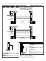
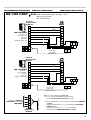
MS 1040 F/RCF
SX18/K18A
9
8
OUT
6
4
N
5
L
6
4
N
5
L
3
N
1
MS 1040 F/RCF
SX18/K18A
9
8
OUT
MS 1040 F/RCF SX 18 ou K 18 A AVEC ou SANS chauffage électrique
SX 18 or K 18 A WITH or WITHOUT electric heating
SX 18 oder K 18 A MIT oder OHNE elektroheizung
1 A raccorder uniquement en REVERSIBLE
To be connected in HEATPUMP configuration only
Nur bei WÄRMEPUMPENAUSFÜHRUNG anschließen
Fil de sonde
Sensor wire
Faden von sonde
Bornier X2
Terminal strip X2
Klemme X2
Groupe n° 2
partie supérieure
n°2 Group
upper part
Aggregat 2 oberer Teil
Le MS 1040 F/RCF est livré configuré pour un raccorde-
ment en : TRIPHASÉ
The MS 1040 F/RCF supplied is configured for THREE-
PHASE connection
MS 1040 F/RCF wird für einen DREHSTROMAN-
SCHLUSS konfiguriert geliefert
Le MS 1040 F/RCF peut-être configuré pour un raccor-
dement en : MONOPHASÉ
Mettre les shunts fournis, comme indiqué ci-contre sur
ce bornier.
The MS 1040 F/RCF supplied is configured for SIN-
GLE-PHASE connection
Install the shunts supplied on the terminal board as
shown opposite.
MS 1040 F/RCF wird für einen
EINPHASENSTROMANSCHLUSS konfiguriert
geliefert
Die beiliegenden Brücken wie nebenstehend
beschrieben auf diese Klemmleiste montieren.
RACCORDEMENTS ÉLECTRIQUES ELECTRIC CONNECTIONS ELEKTRISCHE ANSCHLÜSSE
Fil de sonde
Sensor wire
Faden von sonde
Bornier X1
Terminal strip X1
Klemme X1
Groupe n° 1
partie supérieure
n°1Group
upper part
Aggregat 1 oberer Teil
Bornier
X
Terminal strip X
Klemme X
Bornier X
Terminal strip X
Klemme X
V
W
U
N
N
3N~400V-50Hz
V
W
U
N
N
~230 V - 50Hz

20
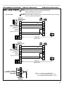
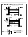
66
44
N
55
L
99
88
3
N
L1
L
1
GTW 18F
MS 1040 F/RCF
66
44
N
55
L
99
88
3
N
L1
L
1
GTW 18F
MS 1040 F/RCF
MS 1040 F/RCF GTW 18 F AVEC ou SANS chauffage électrique
WITH or WITHOUT electric heating
MIT oder OHNE elektroheizung
Fil de sonde
Sensor wire
Faden von sonde
Bornier X2
Terminal strip X2
Klemme X2
Groupe n° 2
partie supérieure
n°2 Group
upper part
Aggregat 2 oberer Teil
Fil de sonde
Sensor wire
Faden von sonde
Bornier X1
Terminal strip X1
Klemme X1
Groupe n° 1
partie supérieure
n°1Group
upper part
Aggregat 1 oberer Teil
RACCORDEMENTS ÉLECTRIQUES ELECTRIC CONNECTIONS ELEKTRISCHE ANSCHLÜSSE
1 A raccorder uniquement en REVERSIBLE
To be connected in HEATPUMP configuration only
Nur bei WÄRMEPUMPENAUSFÜHRUNG anschließen
Le MS 1040 F/RCF peut-être configuré pour un rac-
cordement en : MONOPHASÉ
Mettre les shunts fournis, comme indiqué ci-contre
sur ce bornier.
The MS 1040 F/RCF supplied is configured for
SINGLE-PHASE connection
Install the shunts supplied on the terminal board
as shown opposite.
MS 1040 F/RCF wird für einen
EINPHASENSTROMANSCHLUSS konfiguriert
geliefert
Die beiliegenden Brücken wie nebenstehend
beschrieben auf diese Klemmleiste montieren.
Bornier X
Terminal strip X
Klemme X
Le MS 1040 F/RCF est livré configuré pour un raccorde-
ment en : TRIPHASÉ
The MS 1040 F/RCF supplied is configured for THREE-
PHASE connection
MS 1040 F/RCF wird für einen DREHSTROMAN-
SCHLUSS konfiguriert geliefert
Bornier X
Terminal strip X
Klemme X
V
W
U
N
N
3N~400V-50Hz
V
W
U
N
N
~230 V - 50Hz
Seite wird geladen ...
Seite wird geladen ...
Seite wird geladen ...
Seite wird geladen ...
Seite wird geladen ...
Seite wird geladen ...
Seite wird geladen ...
-
 1
1
-
 2
2
-
 3
3
-
 4
4
-
 5
5
-
 6
6
-
 7
7
-
 8
8
-
 9
9
-
 10
10
-
 11
11
-
 12
12
-
 13
13
-
 14
14
-
 15
15
-
 16
16
-
 17
17
-
 18
18
-
 19
19
-
 20
20
-
 21
21
-
 22
22
-
 23
23
-
 24
24
-
 25
25
-
 26
26
-
 27
27


Airwell K 24 A Benutzerhandbuch
- Typ
- Benutzerhandbuch
- Dieses Handbuch eignet sich auch für
in anderen Sprachen
- English: Airwell K 24 A User manual
- français: Airwell K 24 A Manuel utilisateur
Verwandte Artikel
Andere Dokumente
-
Fakir Airwell Bedienungsanleitung
-
Amprobe ACF-3000-SR Current Transducer Benutzerhandbuch
-
mundoclima MUP-24 CE Bedienungsanleitung
-
 WURM GTW-LAN 2.1 Produktinformation
-
Carrier AQUASNAP 30RH 021 Benutzerhandbuch
-
Blaupunkt GTW 1200 Bedienungsanleitung
-
Blaupunkt GTW 1200 MK II Bedienungsanleitung
-
CIAT AQUACIAT POWER ILD Series User Brochure
