BITZER VARIPACK IP20/IP55/66 Bedienungsanleitung
- Typ
- Bedienungsanleitung

OPERATING INSTRUCTIONS
BETRIEBSANLEITUNG
INSTRUCTIONS DE SERVICE
CB-110-4
VARIPACK - External BITZER Frequency Inverters (FI)
Translation of the original operating instructions
English...................................................................................................................................................... 2
VARIPACK - Externe BITZER Frequenzumrichter (FU)
Originalbetriebsanleitung
Deutsch .................................................................................................................................................... 48
VARIPACK – Convertisseurs de fréquences externes (CF) BITZER
Traduction des instructions de service d’origine
Français.................................................................................................................................................... 93
FMY+6-4, FMY+10-4, FMY+14-4
FNY+18-4, FNY+24-4, FNY+30-4
FOY+39-4, FOY+46-4
FPW+61-4, FPW+72-4, FPW+90-4
FQW+110-4, FQW+150-4, FQW+180-4
FRW+202-4, FRW+240-4, FRW+302-4
FSW+370-4 , FSW+480-4
FMU+6-4, FMU+10-4
FNU+14-4, FNU+18-4, FNU+24-4
FOU+30-4, FOU+39-4, FOU+46-4
FPU+61-4, FPU+72-4, FPU+90-4
FQU+110-4, FQU+150-4,
FQU+180-4, FQU+202-4
FSU+370-4, FSU+480-4
Document for electrically skilled installers
Dokument für elektrisch unterwiesene Monteure
Document pour des monteurs instrués électriquement

CB-110-42
Table of contents
1 Introduction........................................................................................................................................................ 3
2 Safety .................................................................................................................................................................. 3
2.1 Authorized staff.......................................................................................................................................... 3
2.2 Residual risks ............................................................................................................................................ 3
2.3 Personal protective equipment .................................................................................................................. 3
2.4 Safety references....................................................................................................................................... 3
2.4.1 General safety references........................................................................................................... 3
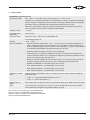
3 Technical data.................................................................................................................................................... 5
4 Mounting............................................................................................................................................................. 7
4.1 Transport and storage ............................................................................................................................... 7
4.2 Ventilation .................................................................................................................................................. 7
4.2.1 Calculation of the required airflow of an enclosure (IP20)........................................................... 8
4.3 Dimensional drawings................................................................................................................................ 9
5 Electrical connection....................................................................................................................................... 10
5.1 ECO design IEC61800-9-2 ...................................................................................................................... 11
5.2 Cable cross-sections and tightening torques........................................................................................... 13
5.3 Connector cover removal IP55/66 ........................................................................................................... 14
5.4 Earth connection...................................................................................................................................... 14
5.5 Information for UL compliance................................................................................................................. 14
5.6 Power connections (voltage supply cable and motor cable).................................................................... 15
5.7 Control connections (inputs and outputs) ................................................................................................ 16
5.8 Operating modes ..................................................................................................................................... 18
5.8.1 Setpoint input selection ............................................................................................................. 18
5.8.2 Capacity control of the compressor depending on an external setpoint signal (P2-27) ............ 18
5.8.3 Capacity control of the compressor as a function of the evaporation pressure......................... 19
5.9 Electromagnetic compatibility (EMC)....................................................................................................... 20
5.9.1 Internal EMC Filter and Varistors – Disconnection Procedure .................................................. 21
5.9.2 Analysis of harmonics ............................................................................................................... 22
5.10 Safe Torque Off (STO) ............................................................................................................................ 25
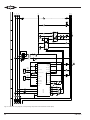
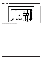
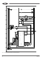
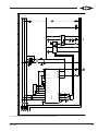
5.11 Schematic wiring diagrams...................................................................................................................... 28
6 Control functions............................................................................................................................................. 36
6.1 Extension module for pressure control .................................................................................................... 37
7 Commissioning................................................................................................................................................ 40
8 Operation.......................................................................................................................................................... 41
9 Fault messages and monitoring functions ................................................................................................... 47
10 Maintenance ..................................................................................................................................................... 47

CB-110-4 3
1 Introduction
The VARIPACK frequency inverters (FI) have been de-
veloped for use in refrigeration, especially for capacity
control of BITZER compressors. In addition to speed
control, the VARIPACK frequency inverters can also
take over control functions of the refrigeration system.
These Operating Instructions describe the
BITZER VARIPACK frequency inverters for refrigera-
tion compressors. For further information on program-
ming the ModbusRTU interface, see
BEST SOFTWARE.
The VARIPACK frequency inverters have been built in
accordance with state-of-the-art methods and current
regulations. Particular importance has been placed on
user safety. The supplied Operating Instructions
CB-111/CB-112/CB-113 must be kept available in the
vicinity of the VARIPACK frequency inverter!
2 Safety
2.1 Authorized staff
All work done on frequency inverters may only be per-
formed by qualified and authorized staff who have been
trained and instructed accordingly. Local regulations
and guidelines apply with respect to the staff's qualifica-
tion and expertise.
2.2 Residual risks
The products, electronic accessories and further sys-
tem components may present unavoidable residual
risks. Therefore, any person working on it must care-
fully read this document! The following are mandatory:
• relevant safety regulations and standards
• generally accepted safety rules
• EU directives
• national regulations and safety standards
Depending on the country, different standards are ap-
plied when installing the product, for example: EN378,
EN60204, EN60335, ENISO14120, ISO5149,
IEC60204, IEC60335, ASHRAE15, NEC, UL stand-
ards.
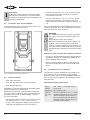
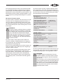
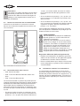
2.3 Personal protective equipment
When working on systems and their components: Wear
protective work shoes, protective clothing and safety
goggles. In addition, wear cold-protective gloves when
working on the open refrigeration circuit and on com-
ponents that may contain refrigerant.
Fig.1: Wear personal protective equipment!
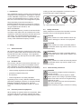
2.4 Safety references
Safety references are instructions intended to prevent
hazards. They must be stringently observed!
!
!
NOTICE
Safety reference to avoid situations which may
result in damage to a device or its equipment.
CAUTION
Safety reference to avoid a potentially hazard-
ous situation which may result in minor or mod-
erate injury.
WARNING
Safety reference to avoid a potentially hazard-
ous situation which could result in death or seri-
ous injury.
DANGER
Safety reference to avoid an imminently hazard-
ous situation which may result in death or seri-
ous injury.
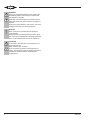
2.4.1 General safety references
DANGER
Life-threatening voltages inside the frequency
inverter housing!
Contact can lead to serious injuries or death.
Never open the FI housing in operation! Switch
off the main switch and secure it against being
switched on again.
Wait for at least 10 minutes until all capacitors
have been discharged!
Before switching on again, close the FI housing.

CB-110-44
DANGER
Wrong or insufficient earthing may result in life-
threatening electric shocks upon contact with
the frequency inverter!
Earth the complete frequency inverter perman-
ently and check the earth contacts at regular in-
tervals!
Prior to any intervention in the device, check all
voltage connections for proper isolation.
!
!
NOTICE
Risk of frequency inverter failure caused by
over-voltage!
Always disconnect the frequency inverter from
the circuit to be tested before any high potential
tests or an isolation test on lines in operation!
CAUTION
In operation, the heat sink of the frequency in-
verter will get hot.
Risk of burns upon contact!
Prior to performing work on the frequency in-
verter, disconnect the power supply and wait for
at least 15 minutes until the heat sink has
cooled down.

CB-110-4 5
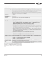
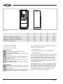
3 Technical data
VARIPACK frequency inverter
Operating voltage 380 .. 480 V +/- 10% (TN and TT mains supply), 50 ... 60 Hz +/- 5%
Operation on IT networks possible for F.U (IP20) and F.Y (IP66). To obtain compatibility
with this network configuration and the network monitoring installed there, the integrated
EMC filters must be deactivated and special external filters must be used.
Operation on generators, emergency power units and networks equipped with power
factor correction units only after consultation with BITZER.
Leakage current < 20mA
Permitted phase
asymmetry
maximum 3%
Enclosure class Enclosure rating - IP20, IP55 or IP66 (NEMA 4X)
Overvoltage categoryIII
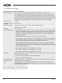
Storage -40°C .. +60°C
Place of installation • Permitted ambient temperature: -10°C .. +50°C. From 40°C ambient temperature on-
wards, continuous output current capacity of 1.5% per degree Celsius for IP55 and
2.5% for IP66 (derating). FI size FPU+90: > 35°C: Derating: 1,1% per °C. The selection
in the BITZER SOFTWARE can take this directly into account.
• Permitted relative humidity: max. 95%, non-condensing.
• F.W (IP55) and F.Y (IP66) are designed to operate in 3S3/3C3 environments in ac-
cordance with IEC 60721-3-3. F.U (IP20) are designed to operate in 3S2/3C2 environ-
ments in accordance with IEC 60721-3-3.
• Maximum permitted altitude abovesea level: 4000m. From 1000m above sea level
onwards, capacity reduction by 1% per 100 m (derating). The selection in the
BITZER SOFTWARE can take this directly into account.
• IP20: Pollution degree 1, non-flammable, non-corrosive.
IP55: Pollution degree 2, non-flammable, non-corrosive.
IP66: Pollution degree 4, non-flammable, non-corrosive.
Vibrations / oscilla-
tions
Test according to EN 60068-2-6 (Fc), 10 cycles per axis on each of three mutually per-
pendicular axes:
• 10Hz<f<57Hz sinusoidal amplitude 0.075mm.
• 57Hz<f<150Hz sinusoidal 1g.
Safe Torque Off
(STO)
Safe Torque Off is a safety function for the electrical power drive, Safe Torque Off (STO).
EMC The compressor with frequency inverter (FI) meets the EU EMC directive 2014/30/EU,
see chapter Electromagnetic compatibility (EMC), page 20.
The selection and assignment of the VARIPACK fre-
quency inverters to the BITZER reciprocating com-
pressors is done by means of the BITZER SOFTWARE
using the ACCESSORIES button.

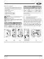
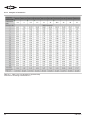
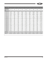
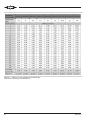
CB-110-46
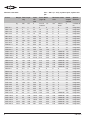
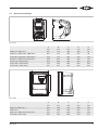
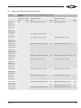
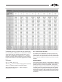
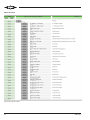
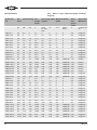
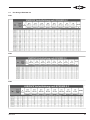
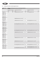
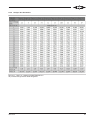
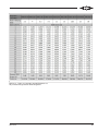
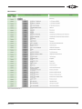
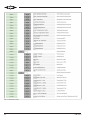
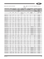
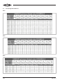
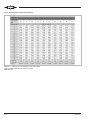
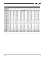
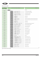
Nominal value table 380 ... 480V (+/- 10%), 3-phase input, 3-phase out-
put
FI size Weight Rated capa-
city
Input
cur-
rent
Fuse / MCB
(Type B)
Maximum cable
size
Rated
output
current
Special
features
kg kW HP A non UL
conform
UL mm2AWG /
kcmil
A C2 EMC fil-
ter
FMY+6-4 4.8 2.2 3 4.7 6 6 8 8 5.8 Integrated
FMY+10-4 4.8 4 5 7.7 10 10 8 8 9.5 Integrated
FMY+14-4 4.8 5.5 7.5 11.4 16 15 8 8 14 Integrated
FNY+18-4 7.7 7.5 10 15 25 20 8 8 18 Integrated
FNY+24-4 7.7 11 15 20.5 25 25 8 8 24 Integrated
FNY+30-4 7.7 15 20 25.3 32 35 8 8 30 Integrated
FOY+39-4 9.5 18.5 25 35.2 50 45 16 5 39 Integrated
FOY+46-4 9.5 22 30 42.2 63 60 16 5 46 Integrated
FPW+61-4 23 30 40 52.3 63 70 35 2 61 Integrated
FPW+72-4 23 37 50 62.5 80 80 35 2 72 Integrated
FPW+90-4 23 45 60 79.5 100 100 35 2 90 Integrated
FQW+110-4 55 55 75 126.4 160 175 150 300MCM 110 External*
FQW+150-4 55 75 100 164.7 200 200 150 300MCM 150 External*
FQW+180-4 55 90 150 192.1 250 250 150 300MCM 180 External*
FRW+202-4 89 110 175 210.8 315 300 150 300MCM 202 External*
FRW+240-4 89 132 200 241 315 300 150 300MCM 240 External*
FRW+302-4 89 160 250 299 400 400 150 300MCM 302 External**
FSW+370-4 132 200 300 370 500 500 240 450MCM 370 Integrated
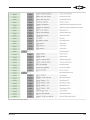
FSW+480-4 132 250 400 480 600 600 240 450MCM 480 Integrated
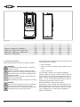
FMU+6-4 1.8 2.2 3 4.8 6 6 8 8 5.8 Integrated
FMU+10-4 1.8 4 5 8.2 10 10 8 8 9.5 Integrated
FNU+14-4 3.5 5.5 7.5 11.5 16 15 8 8 14 Integrated
FNU+18-4 3.5 7.5 10 15.7 25 20 8 8 18 Integrated
FNU+24-4 3.5 11 15 21.3 32 30 8 8 24 Integrated
FOU+30-4 9.5 15 20 25 32 30 16 8 30 Integrated
FOU+39-4 9.5 18.5 25 32.8 50 40 16 5 39 Integrated
FOU+46-4 9.5 22 30 39.3 50 50 16 5 46 Integrated
FPU+61-4 18.1 30 40 52.3 63 70 35 5 61 Integrated
FPU+72-4 18.1 37 50 62.5 80 80 35 2 72 Integrated
FPU+90-4 18.1 45 60 79.5 100 100 35 2 90 Integrated
FQU+110-4 32 55 75 102.2 125 125 150 300MCM 110 Integrated
FQU+150-4 32 75 100 138.2 200 175 150 300MCM 150 Integrated
FQU+180-4 43 90 150 167.4 250 225 150 300MCM 180 Integrated
FQU+202-4 43 110 175 189.8 250 250 150 300MCM 202 Integrated
FSU+370-4 124.5 200 300 370 500 500 240 450MCM 370 Integrated
FSU+480-4 124.5 250 400 480 600 600 240 450MCM 480 Integrated

CB-110-4 7
* External EMC filter for C2 EMC limit: Part number:
347 955 02, designation: FN 3359-250-28
** External EMC filter for C2 EMC limit: Part number:
347 955 03, designation: FN 3359-320-99
4 Mounting
All FI sizes:
• The frequency inverter must be mounted in a vertical
position only.
• Refer to technical data and ensure the chosen
mounting location is within the FI specification.
• The mounting location must be free from vibration.
IP20:
• IP20 units must be mounted in a switch cabinet.
IP55/66:
• Installation should be on a suitable flat, flame resist-
ant surface. Do not mount flammable material close
to the FI.
• Do not mount the FI in any area with excessive hu-
midity, corrosive airborne chemicals or potentially
dangerous dust particles.
• Do not mount close to high heat sources.
• The FI must not be mounted in direct sunlight. If ne-
cessary, install a suitable shade cover.
• Do not restrict the flow of air through the FI heatsink.
The FI generates heat which must be naturally al-
lowed to dissipate. Correct air clearance around the
FI must be observed.
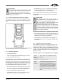
4.1 Transport and storage
!
!
NOTICE
Risk of damage to the frequency inverter!
Do not lift or put down the frequency inverter on
the connections.
Place it on clean, flat and dry surfaces only.
Storage in well-ventilated places only and pro-
tected from high temperatures, humidity, dust
and metal particles!
Information
If the FI (FQ. and FR. series) has been in stor-
age for a period longer than 2 years, the DC link
capacitors must be reformed.
Fig.2: Reformation
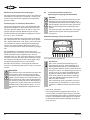
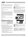
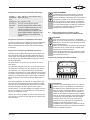
4.2 Ventilation
!
!
NOTICE
The frequency inverters give off heat during op-
eration. Typical drive heat losses are 2% of op-
erating load conditions.
Insufficient or blocked air circulation and air sup-
ply at the heat sink of the frequency inverter can
lead to failure due to overheating!
Observe the minimum clearances for ventilation!
Fig.3: Minimum ventilation clearances
FI size X Y
FMU, FNU 100 mm 10 mm
FOU .. FQU 200 mm 25 mm
F.Y .. F.W 200 mm 10 mm
FS. 400 mm 10 mm

CB-110-48
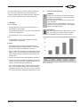
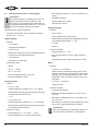
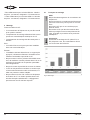
4.2.1 Calculation of the required airflow of an
enclosure (IP20)
If the panel is to be ventilated using cooling fans and fil-
ters, the required airflow can be determined as follows:
• F = 0.053 x P / (TMAX – TAMB)
Where
• F = Airflow in cubic metres per minute
• P = Total power dissipated in panel (include all
losses from all power devices)
• TMAX = Maximum temperature allowed in the panel
(ambient temperature for the drive)
• TAMB = Maximum ambient temperature around the
panel

CB-110-4 9
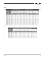
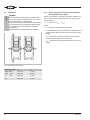
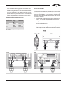
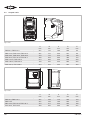
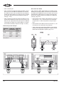
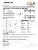
4.3 Dimensional drawings
E
A
B
D
C
Fig.4: IP20
A
mm
B
mm
C
mm
D
mm
E
mm
FMU+6-4, FMU+10-4 221 110 185 209 63
FNU+14-4, FNU+18-4, FNU+24-4 261 131 205 247 80
FOU+30-4, FOU+39-4, FOU+46-4 418 172 240 400 125
FPU+61-4, FPU+72-4, FPU+90-4 486 233 260 460 175
FQU+110-4, FQU+150-4 614 286 320 578 200
FQU+180-4, FQU+202-4 726 330 320 680 225
FSU+370-4, FSU+480-4 974 444 423 924 320
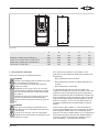
E
C
D
A
B
Fig.5: IP66
A
mm
B
mm
C
mm
D
mm
E
mm
FMY+6-4, FMY+10-4 257 188 172 200 176
FMY+14-4 257 188 196 200 176
FNY+18-4, FNY+24-4, FNY+30-4 310 211 225 252 198
FOY+39-4, FOY+46-4 360 240 260 300 227

CB-110-410
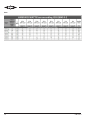
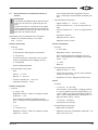
D
E
A
BC
Fig.6: IP55
A
mm
B
mm
C
mm
D
mm
E
mm
FPW+61-4, FPW+72-4, FPW+90-4 540 235 270 520 175
FQW+110-4, FQW+150-4, FQW+180-4 865 330 330 840 200
FRW+202-4, FRW+240-4, FRW+302-4 1280 330 360 1255 200
FSW+370-4, FSW+480-4 1334 444 423 924 320
5 Electrical connection
Before performing any work on the electrical system:
DANGER
Life-threatening voltages inside the frequency
inverter housing!
Contact can lead to serious injuries or death.
Never open the FI housing in operation! Switch
off the main switch and secure it against being
switched on again.
Wait for at least 10 minutes until all capacitors
have been discharged!
Before switching on again, close the FI housing.
DANGER
As soon as the frequency inverter is energised,
the capacitors in the DC link are charged.
From this moment on, all electrical components
in the frequency inverter present risks!
The operation of the frequency inverter requires the fol-
lowing electrical connections:
• earth connection.
• power connections (voltage supply cable and motor
cable).
• control connections.
For the design of cable cross-sections, tightening
torques of earth and power connections and fuses see
chapter Cable cross-sections and tightening torques,
page 13. Fuses of type gG (IEC 60269) or UL fuses of
type J, T or CC, or thermal overload switches with cor-
responding characteristics must be used.
A fixed installation is required according to
IEC61800-5-1 with a suitable disconnecting device in-
stalled between the FI and the AC power source. The
disconnecting device must conform to the local safety
code / regulations (e.g. within Europe, EN60204-1,
Safety of machinery).

CB-110-4 11
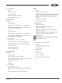
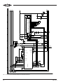
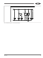
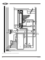
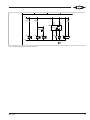
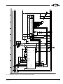
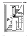
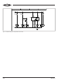
5.1 ECO design IEC61800-9-2
IP20
IP55

CB-110-412
IP66

CB-110-4 13
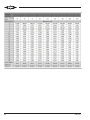
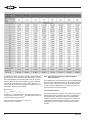
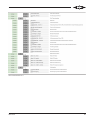
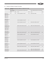
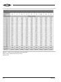
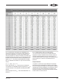
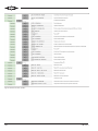
5.2 Cable cross-sections and tightening torques
FI size Maximum cable cross-sections and tightening torques
(in Nm)
Control terminals Power terminals Earth connections
mm2Nm mm2Nm mm2Nm
FMY+6-4 1,5 0,5 Pin cable lug up to 6 mm20,8 M4 Ring cable lug 2
FMY+10-4
FMY+14-4
FNY+18-4
FNY+24-4
FNY+30-4
FOY+39-4 Pin cable lug up to 16 mm22
FOY+46-4
FPW+61-4 Pin cable lug up to 35 mm24 M4 Ring cable lug 35 mm24
FPW+72-4
FPW+90-4
FQW+110-4 M10 Ring cable lug 150 mm215 M10 Ring cable lug 150 mm215
FQW+150-4
FQW+180-4
FRW+202-4
FRW+240-4
FRW+302-4
FSW+370-4 M12 Ring cable lug 240 mm260 M12 Ring cable lug 240 mm260
FSW+480-4
FMU+6-4 Pin cable lug up to 6 mm21 Pin cable lug up to 6 mm21
FMU+10-4
FNU+14-4
FNU+18-4
FNU+24-4
FOU+30-4 Pin cable lug up to 16 mm22 Pin cable lug up to 16 mm22
FOU+39-4
FOU+46-4
FPU+61-4 Pin cable lug up to 35 mm24 Pin cable lug up to 35 mm24
FPU+72-4
FPU+90-4
FQU+110-4 M10 Ring cable lug 150 mm212 M8 Ring cable lug 150 mm212
FQU+150-4
FQU+180-4 15 M10 Ring cable lug 150 mm215
FSU+370-4 M12 Ring cable lug 240 mm260 M12 Ring cable lug 240 mm260
FSU+480-4

CB-110-414
Information
Cable sizes shown are the maximum possible
that may be connected to the FI. Select cables
according to local wiring codes or regulations at
the point of installation.
5.3 Connector cover removal IP55/66
Turn the fastening screws of the connector cover coun-
terclockwise and remove the cover.
Fig.7: Fastening screws for connector cover
5.4 Earth connection
• IP20: Wire end ferrule
• IP66: M4 ring cable lug for mounting on base
• IP55: Normal cable lug
EN61800-5-1 (product standard for adjustable speed
electrical power drive systems) and
DINEN50178DINVDE0160 (Electronic equipment
for use in power installations) have special earthing re-
quirements as soon as an earth leakage current of
3.5mA is exceeded.
• The protective earth conductor cross-section for the
line conductors (L1, L2, L3) <16mm² must be
10mm² with a single wire design or must have two
wires with the respective phase cross-section.
• For line conductors (L1, L2, L3) ≥16 mm² and ≤35
mm², the protective earth conductor must have a
cross section of 16mm².
• For line conductors (L1, L2, L3) >35mm², the pro-
tective earth conductor cross-section must be at
least 50% of that of the line conductors used (L1, L2,
L3).
All exposed metal parts in the VARIPACK frequency in-
verter are protected with a basic insulation and connec-
ted to the protective earth conductor.
WARNING
The VARIPACK frequency inverters can gener-
ate a direct current in the protective earth con-
ductor.
Risk of electric shock upon contact!
Wherever a residual current device (RCD) or a
residual current monitoring device (RCM) is
used for protection against direct or indirect con-
tact, only a RCD or RCM of type B (according to
IEC/EN60755) is permitted on the power supply
side!
Residual current circuit breakers (RCD or FI switch)
• Use only FI circuit breakers (RCD) of type B that are
sensitive to all types of currents and capable of de-
tecting residual direct currents.
• Select a separate RCD for each FI with respect to
the system configuration and environmental condi-
tions.
5.5 Information for UL compliance
The frequency inverter is designed to meet the UL re-
quirements. For an up to date list of UL compliant
products, please refer to UL listing NMMS.E475976. In
order to ensure full compliance, the following must be
fully observed.
Input power supply requirements
Supply
voltage
380 .. 480 V +/- 10% (TN and TT
power grid)
Frequency 50 .. 60 Hz +/- 5%
Short cir-
cuit capa-
city
All FI are suitable for use on a circuit
capable of delivering not more than
100 kA maximum short-circuit cur-
rent symmetrical with the specified
maximum supply voltage when pro-
tected by class J fuses.

CB-110-4 15
Mechanical installation requirements
All frequency inverter units are intended for installation
within controlled environments which meet the condi-
tion limits shown in the technical data section.
Electrical installation requirements
Suitable power and motor cables should be selected
according to the data shown in technical data section
and the National Electrical Code or other applicable
local codes.
Motor Cable: min. 75°C copper must be used.
Integral solid state short circuit protection does not
provide branch circuit protection. Branch circuit protec-
tion must be provided in accordance with the national
electrical code and any additional local codes. Ratings
are shown in the technical data section of this Quick
Start Guide.
For Canadian installations transient surge suppression
must be installed on the line side of this equipment and
shall be rated 480 V (phase to ground), 480 V (phase
to phase), suitable for over voltage category III and
shall provide protection for a rated impulse withstand
voltage peak of 2.5 kV.
UL Listed ring terminals/lugs must be used for all bus
bar and grounding connections.
WARNING
The opening of the branch-circuit protective
device may be an indication that a fault has
been interrupted. To reduce the risk of fire or
electric shock, current-carrying parts and other
components of the controller should be ex-
amined and replaced if damaged. If burnout of
the current element of an overload relay occurs,
the complete overload relay must be replaced.
5.6 Power connections (voltage supply cable and
motor cable)
DANGER
Wrong or insufficient earthing may result in life-
threatening electric shocks upon contact with
the frequency inverter!
Earth the complete frequency inverter perman-
ently and check the earth contacts at regular in-
tervals!
Prior to any intervention in the device, check all
voltage connections for proper isolation.
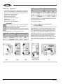
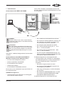
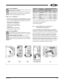
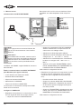
Cable bushing preparation IP55/66
16 | Optidrive Eco Bedienungsanleitung | Revision 3.08 www.invertekdrives.com
3.10. Richtlinien für die Montage (IP66-Geräten)
Stellen Sie vor der Montage des Antriebs sicher, dass der
ausgewählte Antrieb vorhanden ist, der Standort erfüllt die
Umgebungsbedingungen, Anforderungen an den Antrieb
siehe Abschnitt 11.1. Umgebung auf Seite 68.
Der Antrieb muss vertikal an einem geeigneten Ort
montiert werden, auf einer ebenen Fläche.
Die Mindestmontageabstaände wie in der Tabelle
unten müssen beachtet werden.
Der Montageort und die ausgewählten Halterungen sollten
ausreichend sein, um das Gewicht der Antriebe zu tragen.
Verwenden den Antrieb als Vorlage oder dessen
Abmessungen. Markieren Sie die oben gezeigten
Stellen, die zum Bohren erforderlich sind.
Geeignete Kabelverschraubungen zur Aufrechterhaltung
des Eindringschutzes am Antrieb sind erforderlich. Bohrlöcher
für Netzzuleitung und Motorkabel sind in das Antriebsgehäuse vorgeformt, Die empfohlenen Kabekverschraubungsgrößen sind
unten aufgeführt. Kabelberschraubungslöcher für Steuerkabel können nach Bedarf gebohrt werden.
Der Montageort sollte vibrationsfrei sein.
Montieren Sie den Antrieb nicht in Bereichen mit übermäßiger Luftfeuchtigkeit, ätzenden Chemikalien in der Luft oder potenziell
gefährlichen Staubpartikeln.
Vermeiden Sie die Montage in der Nähe von starken Wärmequellen.
Der Antrieb darf nicht direktem Sonnenlicht ausgesetzt werden. Installieren Sie gegebenenfalls eine geeignete Schattenabdeckung.
Der Montageort muss frostfrei sein.
Der Luftstrom durch den Antriebskühlkörper darf nicht eingeschränkt werden. Der Antrieb erzeugt Wärme, die natürlich abgeführt
werden muss. Der korrekte Abstand um den Antrieb muss beachtet werden.
Wenn der Standort starken Schwankungen der Umgebungstemperatur und des Luftdrucks ausgesetzt ist, installieren Sie ein
geeignetes Druckausgleichsventil in der Kabeldurchführungs-Verschraubungsplatte des Antriebs.
HINWEIS Wenn der Frequenzumrichter länger als 2 Jahre gelagert wurde, müssen die Zwischenkreiskondensatoren vor dem ersten
Einschalten reformiert werden.
Umrichter
Baugröße
X– oberhalb & unterhalb Y – beide Seiten
mm in mm in
1 200 7. 87 10 0.39
2 200 7. 87 10 0.39
3 200 7. 87 10 0.39
4 200 7. 87 10 0.39
HINWEIS
Oben sind nur Richtlinien aufgeführt und die Betriebsumgebungstemperatur des Frequenzumrichters
MUSS innerhalb der in Abschnitt 11.1. Umgebung angegebenen Grenzen jederzeit eingehalten werden.
3.11. Kabeldurchführungsplatte
Die Verwendung eines geeigneten Verschraubungssystems ist erforderlich, um die entsprechende IP / NEMA-Schutzart
aufrechtzuerhalten. Die Stopfbuchsenplatte hat vorgeformte Kabeleinführungslöcher für Netz- und Motoranschlüsse, die für die
Verwendung mit Stopfbuchsen geeignet sind (siehe folgende Tabelle). Wenn zusätzliche Löcher erforderlich sind, können diese auf
eine geeignete Größe gebohrt werden. Bitte achten Sie beim Bohren darauf, dass keine Partikel im Antrieb verbleiben.
Empfohlene Kabelverschraubungstypen und Lochgrößen IP66 / NEMA 4X Kabeldurchführungsplatte
Netz- und Motoranschlusskabel
Baugröße Bohrlochgröße Empfohlene PG-
Verschraubung Alternative Metrische-
Verschraubung
Baugröße 1 22 PG16 M20
Baugröße 2 & 3 27 PG21 M25
Baugröße 4 37 PG29 -
Schutzart nach UL-Einstufung ("Typ") wird nur erfüllt, wenn das Kabel mit einer UL-
anerkannten Buchse oder Armatur für ein flexibles Leitungssystem installiert wird,
das das erforderliche Schutzniveau ("Typ") erfüllt.
Für Rohrinstallationen erfordern die Rohreintrittslöcher eine Standardöffnung in
den gemäß NEC angegebenen erforderlichen Größen.
Nicht für die Installation mit einem starren Leitungssystem vorgesehen.
3
Mechanische Installation
Fig.8: Cable bushing plate IP66
Information
The holes for screwed cable glands of voltage
supply, control lines and motor cable (EMC)
must be drilled into the cable bushing plate.
Screwed cable glands for control and bus lines
can alternatively be fitted in the top plastic cover
(IP66). To prevent drilling dust or particles from
entering the housing, the cable bushing plate
must be removed before drilling!
The use of a suitable gland system is required
in order to maintain the appropriate IP / NEMA
rating.
• IP20: Non-existent.
• IP55: Unscrew the cable bushing plate, drill holes for
voltage supply cables, motor cables and control lines
and fit screwed cable glands in the cable bushing
holes. Then fix the plate again (tightening torque: 1
Nm).
• IP66: Unscrew the cable bushing plate and fit the
screwed cable glands in the cable bushing holes
provided. A separate hole must be drilled for the
control cable and fitted with a screwed cable gland.
Then fix the plate again (tightening torque: 0,5 Nm).
Cable gland sizes
FI size Power
cable
Control
cable
M, N PG21,
M25
PG13,3,
M20
O PG29,
M32
PG13,3,
M20
P, Q, R, S - -

CB-110-416
Cable connection
Feed the voltage supply cable and the shielded motor
cable through the screwed cable glands into the VARI-
PACK frequency inverter and connect them to the
power terminals. Observe the tightening torques of the
terminals see chapter Cable cross-sections and tight-
ening torques, page 13!
• Connect the voltage supply cable to the terminals
L1, L2, L3 and the protective earth terminal. Phase
sequence is not important.
• Connect the motor cable to the terminals U, V, W
and the protective earth terminal.
• Observe the information regarding electromagnetic
compatibility (EMC) see chapter Electromagnetic
compatibility (EMC), page 20!
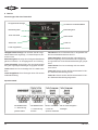
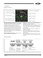
5.7 Control connections (inputs and outputs)
Information
The entire external wiring must be approved for
maximum system voltage!
All control and signal terminals ensure safety
extra low voltages (SELV), i.e., they are protec-
ted by double insulation.
Specification of the control connections:
• Cables with insulated or uninsulated wire end fer-
rules: 0.25..1.5 mm².
Digital inputs
• Function
– 2: DI1 (Start)
Compressor start command.
– 3: DI2 (Force)
Operation of the compressor with a configurable
frequency (50Hz factory setting).
– 4:DI3 (Reset)
Reset of faults.

CB-110-4 17
• Technical data
– Status:
Off: 0..7V DC
On: 8..30V DC
– Max. input voltage: +30V DC
– Input impedance: 10kΩ.
Analogue inputs
• Function
– 6:AI1 (V/p0)
External control: Setpoint as 0..10V signal.
With extension module (pressure control): Input
for low pressure transmitter.
– 7: 0V
– 10:AI2 (mA/pc)
External control: Setpoint as 4..20mA signal.
With extension module (pressure control): Input
for high-pressure transmitter.
• Technical data
– Input signal: 0..10V or 4..20mA
– Max. input current: ≤20mA (current signal)
– Max. input voltage: +30V DC (voltage signal)
– Input impedance:
Voltage range: 86kΩ.
Current range: 500Ω
Analogue outputs
• Function
– 8: AO1 (Fan)
External control: without function.
With extension module (pressure control): Activa-
tion for condenser fan 0..10V.
– 11: AO2
Reserve.
• Technical data
– Output signal: 0..10V.
– Max. output load: 20mA, with short-circuit protec-
tion.
– Output impedance: Voltage range 86kΩ.
Relays
• Function
– 14: RL1-In → 15: RL1-NO
"No fault" (factory setting) or "No fault and no time
delay" or "No fault, no time delay and start" con-
figurable via parameter "Logic of relay 1 (RL1)"
P2-15.
– 17: RL2-A → 18: RL2-B
Compressor is running.
• Technical data
– Potential-free relay.
– Maximum switching current range: 5A
(250VAC / 30VDC)
– Minimum switching current range: 20mA (min.
24VAC / 24VDC)
– Protection against inductive or capacitive loads
must be provided by external measures.
Information
The STO input must be activated to allow the
compressor to start!
STO
• Function Safe Torque Off (STO)
– 12: STO
STO input (Safe Torque Off).
– 13: Common
• Technical data
– Status:
Off: < 18VDC
On: 18 .. 30VDC
– Max. input voltage: +30VDC

CB-110-418
5.8 Operating modes
The VARIPACK frequency inverter can be operated in
two different operating modes:
• Capacity control of the compressor depending on an
external setpoint signal (see chapter Setpoint input
selection, page 18).
• Capacity control of the compressor depending on the
evaporation pressure, which will require the optional
extension module for pressure control (see chapter
Capacity control of the compressor as a function of
the evaporation pressure, page 19).
In addition to direct evaporation pressure control, the
condenser fan can also be controlled via a 0..10V
output signal and a second compressor can be con-
nected.
5.8.1 Setpoint input selection
The VARIPACK frequency inverters can be controlled
via parameter change (P1-13) with a 0...10V (factory
setting) or 4...20mA signal.
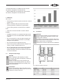
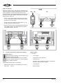
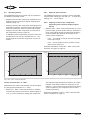
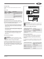
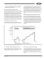
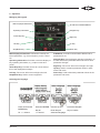
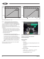
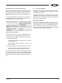
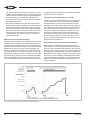
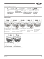
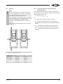
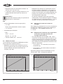
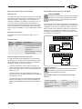
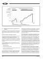
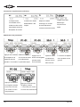
5.8.2 Capacity control of the compressor
depending on an external setpoint signal
(P2-27)
• With the "Min...Max" control characteristic, the com-
pressor starts up when the DI1 start-up command is
given. The setpoint signal provides linear frequency
control between the minimum and maximum fre-
quency of the compressor.
– If a 0..10V signal is used, it must be connected
to the input AI1 (6).
– If a 4..20mA signal is used, it must be connec-
ted to the input AI2 (10).
Graphical explanation of the "Min..Max" control char-
acteristic, see figure 9, page 18.
0
f [Hz]
I [mA]
4 8 12 16 20
4 .. 20 mA
f [Hz]
02 4 6 8 10 12
0U [V]
0 .. 10 V
fmax
fmin
fmax
fmin
Fig.9: "Min..Max" control characteristic
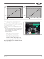
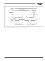
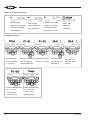
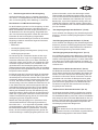
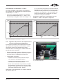
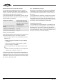
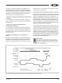
Control characteristic "0..Max"
Alternatively, the control characteristic can be changed
by changing the parameter to "0..Max".
• With the "0..Max" control characteristic, in addition
to the DI1 (2) start-up command, a setpoint signal of
>1% (0.1V) is required for starting the compressor.
The setpoint signal presets the frequency to a value
between 0Hz and the maximum frequency. If the
signal is >1% but lower than the minimum frequency
of the compressor, the compressor will run at the
minimum frequency.
Graphical explanation of the "0..Max" control charac-
teristic, see figure 10, page 19.

CB-110-4 19
0
f [Hz]
I [mA]
8 12 16 20
4 .. 20 mA
f [Hz]
0 2 4 6 8 10 12
U [V]
0 .. 10 V
fmax
fmin
fmax
fmin
4
fmax
user
compr.
user
compr.
user
fmax
user
Fig.10: "0..Max" control characteristic
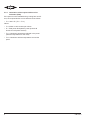
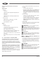
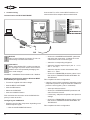
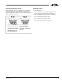
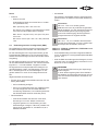
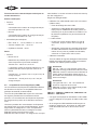
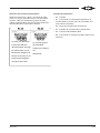
5.8.3 Capacity control of the compressor as a
function of the evaporation pressure
To control the capacity of the compressor as a function
of the evaporation pressure requires the optional exten-
sion module for pressure control.
Installation of the extension module kit (part number
34797202):
• Remove cover of extension slot. Press the extension
module into the extension slot of the FI and tighten
the two screws with a T9 screwdriver.
• Pressure transmitter
– Install the pressure transmitter labelled
"TA-12,8SS" on the low pressure side.
– Install the pressure transmitter labelled
"TA-34,5SS" on the high pressure side.
– In the case of Schrader valves, install the pres-
sure transmitters without a copper gasket ring to
ensure safe opening (max. torque 15Nm).
Wiring of the extension module see chapter Schematic
wiring diagrams, page 28.
Fig.11: Extension module

CB-110-420
Function and technical data of the extension
module
Digital inputs
• Function
– Terminal 1
Switch over from evaporation temperature set-
point 1 to 2.
– Terminal 2
Switch over from condensing temperature set-
point 1 to 2.
• Technical data
– Status: Off: 0 .. 7VDC, On: 8 .. 30VDC
– Max. input voltage: +30VDC
– Input impedance: 10kΩ
Relays
• Function
– Terminals 5 and 6
Potential-free relay for starting the 2ndcom-
pressor (K14 auxiliary relay).
Max. voltage: 250 V AC / 30 V DC
Protection against inductive or capacitive loads
must be provided by external measures.
Max. current: 5 A (250VAC) / 5A (30VDC) res-
istive load.
Min. current: 20mA (24VAC / 24VDC) resistive
load.
5.9 Electromagnetic compatibility (EMC)
The VARIPACK frequency inverters comply with the
EU EMC directives 2014/30/EU and 2004/108/EC.
The product standard EN61800-3 applies to the inter-
ference immunity of frequency inverters. The frequency
inverters meet the requirements for the first and second
environment.
The interference emission of the frequency inverters is
regulated by the product standard EN 61800-3, which
distinguishes between categories C1 – C4. Compared
with the generic standards, the category C2 according
to EN61800-3:2004 corresponds to
EN61000-6-4-2007+A1: 2011. The category C3 is not
transferable. The text below only refers to C categories.
General EMC requirements:
• Use of a shielded cable between FI and motor (mo-
tor cable).
– Connect shield on both sides.
– Route the shielded cable up to the VARIPACK in
the switch cabinet and lay it properly through an
EMC screwed cable gland (IP55/66), resp. con-
nect it with low impedance to the back panel/PE
rail (IP20).
• The motor cable
– should not cross other cables. If it does, crossov-
ers must be made at a 90° angle!
– should be installed separately from the feed line
and the control lines, if possible. If a parallel in-
stallation is unavoidable, maintain a clearance of
at least 0.25m.
• Control Cable
All analog signal cables should be suitably shielded.
Twisted pair cables are recommended.
Information
FM.+6-4 .. FM.+14-4 are classified as profes-
sionally used device according to
EN61000-3-2:2014. Before connecting them to
the public low-voltage supply network, approval
from the energy supply company must be ob-
tained.
Information
FM.+18-4 .. FP.+72-4 meet all requirements of
the standard EN61000-3-12:2011 (see chapter
Analysis of harmonics, page 22).
FMY+6-4 .. FPW+90-4, FSW+370-4, FSW+480-4 and
FMU+6-4 .. FSU+480-4:
• are equipped as standard with an integrated EMC fil-
ter for category C2 (motor cable length max. 5 m) .
• If the EMC requirements of category C3 are suffi-
cient, the line length between FI and motor may be
up to 25m.
WARNING
Without the use of an external EMC filter, high-
frequency interferences may occur in the
voltage supply system!
In a residential environment, this drive constella-
tion may cause high-frequency interferences
which may require mitigation measures.
Seite laden ...
Seite laden ...
Seite laden ...
Seite laden ...
Seite laden ...
Seite laden ...
Seite laden ...
Seite laden ...
Seite laden ...
Seite laden ...
Seite laden ...
Seite laden ...
Seite laden ...
Seite laden ...
Seite laden ...
Seite laden ...
Seite laden ...
Seite laden ...
Seite laden ...
Seite laden ...
Seite laden ...
Seite laden ...
Seite laden ...
Seite laden ...
Seite laden ...
Seite laden ...
Seite laden ...
Seite laden ...
Seite laden ...
Seite laden ...
Seite laden ...
Seite laden ...
Seite laden ...
Seite laden ...
Seite laden ...
Seite laden ...
Seite laden ...
Seite laden ...
Seite laden ...
Seite laden ...
Seite laden ...
Seite laden ...
Seite laden ...
Seite laden ...
Seite laden ...
Seite laden ...
Seite laden ...
Seite laden ...
Seite laden ...
Seite laden ...
Seite laden ...
Seite laden ...
Seite laden ...
Seite laden ...
Seite laden ...
Seite laden ...
Seite laden ...
Seite laden ...
Seite laden ...
Seite laden ...
Seite laden ...
Seite laden ...
Seite laden ...
Seite laden ...
Seite laden ...
Seite laden ...
Seite laden ...
Seite laden ...
Seite laden ...
Seite laden ...
Seite laden ...
Seite laden ...
Seite laden ...
Seite laden ...
Seite laden ...
Seite laden ...
Seite laden ...
Seite laden ...
Seite laden ...
Seite laden ...
Seite laden ...
Seite laden ...
Seite laden ...
Seite laden ...
Seite laden ...
Seite laden ...
Seite laden ...
Seite laden ...
Seite laden ...
Seite laden ...
Seite laden ...
Seite laden ...
Seite laden ...
Seite laden ...
Seite laden ...
Seite laden ...
Seite laden ...
Seite laden ...
Seite laden ...
Seite laden ...
Seite laden ...
Seite laden ...
Seite laden ...
Seite laden ...
Seite laden ...
Seite laden ...
Seite laden ...
Seite laden ...
Seite laden ...
Seite laden ...
Seite laden ...
Seite laden ...
Seite laden ...
Seite laden ...
Seite laden ...
Seite laden ...
Seite laden ...
Seite laden ...
-
 1
1
-
 2
2
-
 3
3
-
 4
4
-
 5
5
-
 6
6
-
 7
7
-
 8
8
-
 9
9
-
 10
10
-
 11
11
-
 12
12
-
 13
13
-
 14
14
-
 15
15
-
 16
16
-
 17
17
-
 18
18
-
 19
19
-
 20
20
-
 21
21
-
 22
22
-
 23
23
-
 24
24
-
 25
25
-
 26
26
-
 27
27
-
 28
28
-
 29
29
-
 30
30
-
 31
31
-
 32
32
-
 33
33
-
 34
34
-
 35
35
-
 36
36
-
 37
37
-
 38
38
-
 39
39
-
 40
40
-
 41
41
-
 42
42
-
 43
43
-
 44
44
-
 45
45
-
 46
46
-
 47
47
-
 48
48
-
 49
49
-
 50
50
-
 51
51
-
 52
52
-
 53
53
-
 54
54
-
 55
55
-
 56
56
-
 57
57
-
 58
58
-
 59
59
-
 60
60
-
 61
61
-
 62
62
-
 63
63
-
 64
64
-
 65
65
-
 66
66
-
 67
67
-
 68
68
-
 69
69
-
 70
70
-
 71
71
-
 72
72
-
 73
73
-
 74
74
-
 75
75
-
 76
76
-
 77
77
-
 78
78
-
 79
79
-
 80
80
-
 81
81
-
 82
82
-
 83
83
-
 84
84
-
 85
85
-
 86
86
-
 87
87
-
 88
88
-
 89
89
-
 90
90
-
 91
91
-
 92
92
-
 93
93
-
 94
94
-
 95
95
-
 96
96
-
 97
97
-
 98
98
-
 99
99
-
 100
100
-
 101
101
-
 102
102
-
 103
103
-
 104
104
-
 105
105
-
 106
106
-
 107
107
-
 108
108
-
 109
109
-
 110
110
-
 111
111
-
 112
112
-
 113
113
-
 114
114
-
 115
115
-
 116
116
-
 117
117
-
 118
118
-
 119
119
-
 120
120
-
 121
121
-
 122
122
-
 123
123
-
 124
124
-
 125
125
-
 126
126
-
 127
127
-
 128
128
-
 129
129
-
 130
130
-
 131
131
-
 132
132
-
 133
133
-
 134
134
-
 135
135
-
 136
136
-
 137
137
-
 138
138


BITZER VARIPACK IP20/IP55/66 Bedienungsanleitung
- Typ
- Bedienungsanleitung
in anderen Sprachen
Verwandte Papiere
Sonstige Unterlagen
-
 Ditel KOS541 Technical Manual
-
 iotty E2PLUS WiFi Connected Smart Switch Benutzerhandbuch
-
LIVARNO 434404 Bedienungsanleitung
-
 Sentera Controls FI-E11043E6-19 Mounting Instruction
-
Lutz Centrifugal immersion pump B50 Bedienungsanleitung
-
 Sentera Controls FI-E13023E2 Mounting Instruction
-
DAB ACTIVE DRIVER PLUS Bedienungsanleitung
-
 Sentera Controls FISE11043E6-19 Mounting Instruction
-
 Sentera Controls FISE11105E6-19 Mounting Instruction
-
 Speck pumpen SPR-I 030 Bedienungsanleitung


