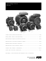
ABB M2F series Installation, Operation & Maintenance Manual
- Typ
- Installation, Operation & Maintenance Manual

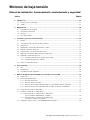
Installation, operation, maintenance and safety manual .......................................................................................... EN 3
Montage-, Betriebs-, Wartungs- und Sicherheitsanleitung .................................................................................... DE 21
Manuel d’installation, d’exploitation, de maintenance et de sécurité ..................................................................... FR 39
Manual de instalación, funcionamiento, mantenimiento y seguridad ..................................................................... ES 59
Manuale d’installazione, funzionamento e manutenzione ........................................................................................ IT 79
Manual de instalação, operação, manutenção e segurança ...................................................................................PT 99
Installations-, driffts-, underhålls- och säkerhetsmanual ..................................................................................... SV 119
Asennus-, käyttö-, kunnossapito- ja turvallisuusohje ............................................................................................ FI 137
More languages – see web site www.abb.com/motors&generators > Motors > Document library
Low voltage motors
Manual

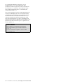
Layout of EC Declaration of Conformity
The Manufacturer: (Name and address of the manufacturer)
hereby declares that
The Products: (Product identication)
are in conformity with the corresponding essential requirements of following EC directive:
Directive 2006/95/EC (of 12 December 2006).
The motors are in conformity with provisions of the harmonized standard EN 60 034-1(2010) which thus
comply with Principal Elements of the Safety Objectives for Electrical Equipment stated in Annex I of
said directive.
Note: When installing motors for converter supply applications, additional requirements must be
respected regarding the motor as well as the installation, as described in installation manual delivered
with converters.
Directive 2009/125/EC (of 21
st
October 2009).
The motors are in conformity with requirements set in the Regulation (EC) N° 640/2009
dated of 22 July 2009.
Efciency class is dened according to the standard EN 60034-30 : March 2009.
Year of CE marking :
Signed by
____________________________
Title ____________________________
Date ____________________________
2 ABB Motors and Generators | Low voltage motor manual 01-2009

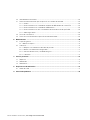
1. Introduction ............................................................................................................................................. 5
1.1 Declaration of Conformity .................................................................................................................. 5
1.2 Validity .............................................................................................................................................. 5
2. Handling ................................................................................................................................................... 6
2.1 Reception check ............................................................................................................................... 6
2.2 Transportation and storage ............................................................................................................... 6
2.3 Lifting ................................................................................................................................................ 6
2.4 Machine weight ................................................................................................................................. 6
3. Installation and commissioning ............................................................................................................. 7
3.1 General ............................................................................................................................................. 7
3.2 Insulation resistance check ............................................................................................................... 7
3.3 Foundation ........................................................................................................................................ 7
3.4 Balancing and fitting coupling halves and pulleys .............................................................................. 8
3.5 Mounting and alignment of the motor ................................................................................................ 8
3.6 Slide rails and belt drives ................................................................................................................... 8
3.7 Machines with drain plugs for condensation ...................................................................................... 8
3.8 Cabling and electrical connections .................................................................................................... 8
3.8.1 Connections for different starting methods ............................................................................. 9
3.8.2 Connections of auxiliaries ....................................................................................................... 9
3.9 Terminals and direction of rotation ..................................................................................................... 9
4. Operation ............................................................................................................................................... 10
4.1 Use ................................................................................................................................................. 10
4.2 Cooling ........................................................................................................................................... 10
4.3 Safety considerations ...................................................................................................................... 10
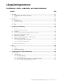
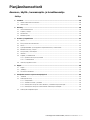
Low Voltage Motors
Installation, operation, maintenance and safety manual
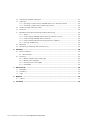
List of Contents Page
Low voltage motor manual 01-2009 | ABB Motors and Generators EN-3

5. Low voltage motors in variable speed operation .............................................................................. 11
5.1 Introduction ..................................................................................................................................... 11
5.2 Winding insulation ........................................................................................................................... 11
5.2.1 Phase to phase voltages ...................................................................................................... 11
5.2.1 Phase to ground voltages .................................................................................................... 11
5.2.3 Selection of winding insulation for ACS550- and ACS800-converters ................................... 11
5.2.4 Selection of winding insulation with all other converters ........................................................ 11
5.3 Thermal protection of windings ....................................................................................................... 11
5.4 Bearing currents .............................................................................................................................. 12
5.4.1 Elimination of bearing currents with ABB ACS550 and ACS800 converters .......................... 12
5.4.2 Elimination of bearing currents with all other converters ........................................................ 12
5.5 Cabling, grounding and EMC .......................................................................................................... 12
5.6 Operating speed ............................................................................................................................. 12
5.7 Dimensioning the motor for variable speed application .................................................................... 12
5.7.1 General ................................................................................................................................ 12
5.7.2 Dimensioning with ABB ACS800 converters with DTC control .............................................. 12
5.7.3 Dimensioning with ABB ACS550 converters ......................................................................... 13
5.7.4 Dimensioning with other voltage source PWM-type converters ............................................. 13
5.7.5 Short time overloads ............................................................................................................ 13
5.8 Rating plates ................................................................................................................................... 13
5.9 Commissioning the variable speed application ................................................................................ 13
6. Maintenance .......................................................................................................................................... 14
6.1 General inspection .......................................................................................................................... 14
6.1.1 Standby motors ......................................................................................................................14
6.2 Lubrication ............................................................................................................................................... 14
6.2.1 Machines with permanently greased bearings ...................................................................... 14
6.2.2 Motors with regreasable bearings ......................................................................................... 15
6.2.3 Lubrication intervals and amounts ........................................................................................ 15
6.2.4 Lubricants ............................................................................................................................ 17
7. After Sales Support ............................................................................................................................... 18
7.1 Spare parts ..................................................................................................................................... 18
7.2 Rewinding ....................................................................................................................................... 18
7.3 Bearings ......................................................................................................................................... 18
8. Environmental requirements ................................................................................................................ 18
8.1 Noise levels ..................................................................................................................................... 18
9. Troubleshooting .................................................................................................................................... 19
EN-4 ABB Motors and Generators | Low voltage motor manual 01-2009

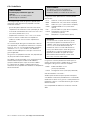
1. Introduction
NOTE!
These instructions must be followed to ensure safe
and proper installation, operation and maintenance
of the machine. They should be brought to the
attention of anyone who installs, operates or
maintains the machine or associated equipment.
The machine is intended for installation and use by
qualified personnel, familiar with health and safety
requirements and national legislation. Ignoring these
instructions may invalidate all applicable warranties.
1.1 Declaration of Conformity
Declarations of Conformity with respect to the Low voltage
Directive 73/23/EEC amended by Directive 93/68 EEC are
issued separately with individual machines.
The Declaration of Conformity also satisfies the
requirements of a Declaration of Incorporation with
respect to the Machinery Directive 98/37/EEC,
Art 4.2 Annex II, sub B
1.2 Validity
The instructions are valid for the following ABB electrical
machine types, in both motor and generator operation.
series MT*, MXMA,
series M2A*/M3A*, M2B*/M3B*, M4B*, M2C*/M3C*,
M2F*/M3F*, M2L*/M3L*, M2M*/M3M*, M2Q*,
M2R*/M3R*, M2V*/M3V*
in frame sizes 56 - 450.
There is a separate manual for e.g. Ex motors ‘Low voltage
motors for hazardous areas: Installation, operation and
maintenance Manual’ (Low Voltage Motors/Manual for Ex-
motors).
Additional information is required for some machine types
due to special application and/or design considerations.
Additional information is available for the following motors:
– roller table motors
– water cooled motors
– open drip proof motors
– smoke venting motors
– brake motors
– motors for high ambient temperatures
Low voltage motor manual 01-2009 | ABB Motors and Generators EN-5

2. Handling
2.1 Reception check
Immediately upon receipt check the motor for external
damage (e.g. shaft-ends and flanges and painted surfaces)
and if found, inform the forwarding agent without delay.
Check all rating plate data, especially voltage and winding
connection (star or delta). The type of bearing is specified
on the rating plate of all motors except the smallest frame
sizes.
2.2 Transportation and storage
The motor should always be stored indoors (above
–20°C), in dry, vibration free and dust free conditions.
During transportation, shocks, falls and humidity should be
avoided. In other conditions, please contact ABB.
Unprotected machined surfaces (shaft-ends and flanges)
should be treated against corrosion.
It is recommended that shafts are rotated periodically by
hand to prevent grease migration.
Anti-condensation heaters, if fitted, are recommended to
be used to avoid water condensing in the motor.
The motor must not be subject to any external vibrations at
standstill so as to avoid causing damage to the bearings.
Motors fitted with cylindrical-roller and/or angular contact
bearings must be fitted with locking devices during
transport.
2.3 Lifting
All ABB motors above 25 kg are equipped with lifting lugs
or eyebolts.
Only the main lifting lugs or eyebolts of the motor should be
used for lifting the motor. They must not be used to lift the
motor when it is attached to other equipment.
Lifting lugs for auxiliaries (e.g. brakes, separate cooling
fans) or terminal boxes must not be used for lifting the
motor.
Motors with the same frame may have a different center of
gravity because of different output, mounting arrangements
and auxiliary equipment.
Damaged lifting lugs must not be used. Check that
eyebolts or integrated lifting lugs are undamaged before
lifting.
Lifting eyebolts must be tightened before lifting. If needed,
the position of the eyebolt can be adjusted using suitable
washers as spacers.
Ensure that proper lifting equipment is used and that the
sizes of the hooks are suitable for the lifting lugs.
Care must be taken not to damage auxiliary equipment and
cables connected to the motor.
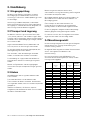
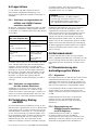
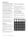
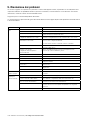
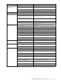
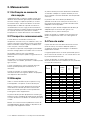
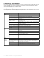
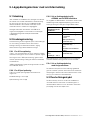
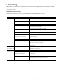
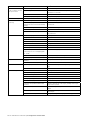
2.4 Machine weight
The total machine weight can vary within the same
frame size (center height) depending on different output,
mounting arrangement and auxiliaries.
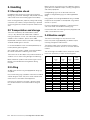
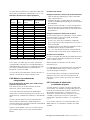
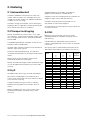
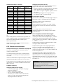
The following table shows estimated maximum weights
for machines in their basic versions as a function of frame
material.
The actual weight of all ABB’s motors, except the smallest
frame sizes (56 and 63) is shown on the rating plate.
Frame
size
Aluminum
Weight
kg
Cast iron
Weight
kg
Steel
Weight
kg
Add.
for brake
56 4.5 - -
63 6 - -
71 8 13 5
80 12 20 8
90 17 30 10
100 25 40 16
112 36 50 20
132 63 90 30
160 95 130 30
180 135 190 45
200 200 275 55
225 265 360 75
250 305 405 75
280 390 800 600 -
315 - 1700 1000 -
355 - 2700 2200 -
400 - 3500 3000 -
450 - 4500 - -
EN-6 ABB Motors and Generators | Low voltage motor manual 01-2009

3. Installation and commissioning
WARNING
Disconnect and lock out before working on the
motor or the driven equipment.
3.1 General
All rating plate values must be carefully checked to ensure
that the motor protection and connection will be properly
done.
WARNING
In case of motors mounted with the shaft upwards
and water or liquids are expected to go down along
the shaft, the user must take in account to mount
some means capable of preventing it.
Remove transport locking if employed. Turn shaft by hand
to check free rotation if possible.
Motors equipped with roller bearings:
Running the motor with no radial force applied to the shaft
may damage the roller bearing.
Motors equipped with angular contact bearing:
Running the motor with no axial force applied in the right
direction in relation to the shaft may damage the angular
contact bearing.
WARNING
For machines with angular contact bearings the axial
force must not by any means change direction.
The type of bearing is specified on the rating plate.
Motors equipped with regreasing nipples:
When starting the motor for the first time, or after long
storage, apply the specified quantity of grease.
For details, see section “6.2.2 Motors with regreasable
bearings”.
3.2 Insulation resistance check
Measure insulation resistance before commissioning and
when winding dampness is suspected.
WARNING
Disconnect and lock out before working on the
motor or the driven equipment.
Insulation resistance, corrected to 25°C, must exceed the
reference value, i.e. 100 MΩ (measured with 500 or 1000 V
DC). The insulation resistance value is halved for each 20°C
rise in ambient temperature.
WARNING
The motor frame must be grounded and the
windings should be discharged against the frame
immediately after each measurement to avoid risk of
electrical shock.
If the reference resistance value is not attained, the
winding is too damp and must be oven dried. The oven
temperature should be 90°C for 12-16 hours followed by
105°C for 6-8 hours.
Drain hole plugs, if fitted, must be removed and closing
valves, if fitted, must be opened during heating. After
heating, make sure the plugs are refitted. Even if the drain
plugs are fitted, it is recommended to disassemble the end
shields and terminal box covers for the drying process.
Windings drenched in seawater normally need to be
rewound.
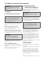
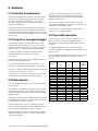
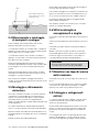
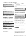
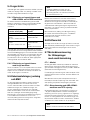
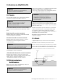
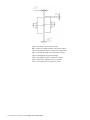
3.3 Foundation
The end user has full responsibility for preparation of the
foundation.
Metal foundations should be painted to avoid corrosion.
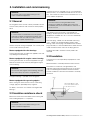
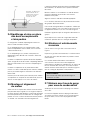
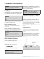
Foundations must be even, see figure below, and
sufficiently rigid to withstand possible short circuit forces.
They must be designed and dimensioned to avoid the
transfer of vibration to the motor and vibration caused by
resonance.
Note! Height difference shall
not exceed ± 0,1mm referred
to any other motor foot
Ruler
Foot location
Low voltage motor manual 01-2009 | ABB Motors and Generators EN-7

3.4 Balancing and fitting coupling
halves and pulleys
As standard, balancing of the motor has been carried out
using half key
When balancing with full key, the shaft is marked with
YELLOW tape, with the text “Balanced with full key”.
In case of balancing without key, the shaft is marked with
BLUE tape, with the text “Balanced without key”.
Coupling halves or pulleys must be balanced after
machining the keyways. Balancing must be done in
accordance with the balancing method specified for the
motor.
Coupling halves and pulleys must be fitted on the shaft by
using suitable equipment and tools which do not damage
the bearings and seals.
Never fit a coupling half or pulley by hammering or by
removing it using a lever pressed against the body of the
motor.
3.5 Mounting and alignment
of the motor
Ensure that there is enough space for free airflow around
the motor. Minimum requirements for free space behind the
motor fan cover can be found from the product catalog or
from the dimension drawings available from the web: see
www.abb.com/motors&generators.
Correct alignment is essential to avoid bearing, vibration
and possible shaft failures.
Mount the motor on the foundation using the appropriate
bolts or studs and place shim plates between the
foundation and the feet.
Align the motor using appropriate methods.
If applicable, drill locating holes and fix the locating pins into
position.
Mounting accuracy of coupling half: check that clearance
b is less than 0.05 mm and that the difference a1 to a2 is
also less than 0.05 mm. See Figure 3.
Re-check the alignment after final tightening of the bolts or
studs.
Do not exceed permissible loading values for bearings as
stated in the product catalogues.
3.6 Slide rails and belt drives
Fasten the motor to the slide rails as shown in Figure 2.
Place the slide rails horizontally on the same level.
Check that the motor shaft is parallel with the drive shaft.
Belts must be tensioned according to the instructions of
the supplier of the driven equipment. However, do not
exceed the maximum belt forces (i.e. radial bearing loading)
stated in the relevant product catalogues.
WARNING
Excessive belt tension will damage bearings and can
cause shaft damage.
3.7 Machines with drain plugs
for condensation
Check that drain holes and plugs face downwards.
Machines with sealable plastic drain plugs are delivered in
open position. In very dusty environments, all drain holes
should be closed.
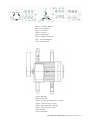
3.8 Cabling and electrical
connections
The terminal box on standard single speed motors normally
contains six winding terminals and at least one earth
terminal.
In addition to the main winding and earthing terminals, the
terminal box can also contain connections for thermistors,
heating elements or other auxiliary devices.
Suitable cable lugs must be used for the connection of all
main cables. Cables for auxiliaries can be connected into
their terminal blocks as such.
Machines are intended for fixed installation only. If not
otherwise specified, cable entry threads are metric. The IP-
class of the cable gland must be at least the same as those
of the terminal boxes.
Unused cable entries must be closed with blanking
elements according to the IP class of the terminal box.
The degree of protection and diameter are specified in the
documents relating to the cable gland.
EN-8 ABB Motors and Generators | Low voltage motor manual 01-2009

WARNING
Use appropriate cable glands and seals in the cable
entries according to the type and diameter of the
cable.
Additional information on cables and glands suitable for
variable speed applications can be found from chapter 5.5.
Earthing must be carried out according to local regulations
before the machine is connected to the supply voltage.
Ensure that the motor protection corresponds to the
environment and weather conditions; for example, make
sure that water cannot enter the motor or the terminal
boxes.
The seals of terminal boxes must be placed correctly in the
slots provided, to ensure the correct IP class.
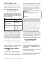
3.8.1 Connections for different
starting methods
The terminal box on standard single speed motors normally
contains six winding terminals and at least one earth
terminal. This enables the use of DOL- or Y/D –starting.
See Figure 1.
For two-speed and special motors, the supply connection
must follow the instructions inside the terminal box or in the
motor manual.
The voltage and connection are stamped on the rating
plate.
Direct-on-line starting (DOL):
Y or D winding connections may be used.
For example, 690 VY, 400 VD indicates Y-connection for
690 V and D-connection for 400 V.
Star/Delta starting (Y/D):
The supply voltage must be equal to the rated voltage of
the motor when using a D-connection.
Remove all connection links from the terminal block.
Other starting methods and severe starting
conditions:
In case other starting methods are used, such as a soft
starter, or if starting conditions are particularly difficult,
please consult ABB first.
3.8.2 Connections of auxiliaries
If a motor is equipped with thermistors or other RTDs
(Pt100, thermal relays, etc.) and auxiliary devices, it is
recommended they be used and connected by appropriate
means. Connection diagrams for auxiliary elements and
connection parts can be found inside the terminal box.
Maximum measuring voltage for the thermistors is 2.5 V.
Maximum measuring current for Pt100 is 5 mA. Using a
higher measuring voltage or current may cause errors in
readings or damage the system.
The insulations of the winding thermal sensors is of basic
type. While connecting the sensors to control systems etc,
ensure adequate insulation or isolation, see IEC 60664.
NOTE!
Ensure the insulation level or isolation of thermistor
circuit, see IEC 60664.
3.9 Terminals and direction
of rotation
The shaft rotates clockwise when viewing the shaft face at
the motor drive end, and the line phase sequence - L1, L2,
L3 - is connected to the terminals as shown in Figure 1.
To alter the direction of rotation, interchange any two
connections on the supply cables.
If the motor has a unidirectional fan, ensure that it rotates in
the same direction as the arrow marked on the motor.
Low voltage motor manual 01-2009 | ABB Motors and Generators EN-9

4. Operation
4.2 Cooling
Check that the motor has sufficient airflow. Ensure that no
nearby objects or direct sunshine radiate additional heat to
the motor.
For flange mounted motors (e.g. B5, B35, V1), make sure
that the construction allows sufficient air flow on the outer
surface of the flange.
4.3 Safety considerations
The machine is intended for installation and use by qualified
personnel, familiar with health and safety requirements and
national legislation.
Safety equipment necessary for the prevention of accidents
at the installation and operating site must be provided in
accordance with local regulations.
WARNING
Do not carry out work on motor, connection cables
or accessories such as frequency converters,
starters, brakes, thermistor cables or heating
elements when voltage is applied.
Points to observe
1. Do not step on the motor.
2. The temperature of the outer casing of the motor
may be too hot to touch during normal operation and
especially after shut-down.
3. Some special motor applications require special
instructions (e.g. using frequency converter supplies).
4. Be aware of rotating parts of the motor.
5. Do not open terminal boxes while energized.
4.1 Use
The motors are designed for the following conditions unless
otherwise stated on the rating plate.
- Normal ambient temperature limits are -20°C to +40°C.
- Maximum altitude 1000 m above sea level.
- Tolerance for supply voltage is ±5% and for frequency
±2% according to EN / IEC 60034-1 (2004).
The motor can only be used in applications it is intended
for. The rated nominal values and operational conditions
are shown on the motor rating plates. In addition, all
requirements of this manual and other related instructions
and standards must be followed.
If these limits are exceeded, motor data and construction
data must be checked. Please contact ABB for further
information.
WARNING
Ignoring any of given instructions or maintenance of
the apparatus may jeopardize the safety and thus
prevents the use of the machine.
EN-10 ABB Motors and Generators | Low voltage motor manual 01-2009

5. Low voltage motors in variable speed operation
5.1 Introduction
This part of the manual provides additional instructions for
motors used in frequency converter supply. Instructions
provided in this and respective manuals of selected
frequency converter must be followed to ensure safety and
availability of the motor.
Additional information may be required by ABB to decide
on the suitability for some machine types used in special
applications or with special design modifications.
5.2 Winding insulation
Variable speed drives cause higher voltage stresses than
the sinusoidal supply on the winding of the motor and
therefore the winding insulation of the motor as well as
the filter at the converter output must be dimensioned
according following instructions.
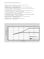
5.2.1 Phase to phase voltages
The maximum allowed phase to phase voltage peaks at
the motor terminal as a function of the rise time of the pulse
can be seen in Figure 1.
The highest curve “ABB Special Insulation” applies to
motors with a special winding insulation for frequency
converter supply, variant code 405.
The “ABB Standard Insulation” applies to all other motors
covered by this manual.
5.2.2 Phase to ground voltages
The allowed phase to ground voltage peaks at motor
terminals are:
Standard Insulation 1300 V peak
Special Insulation 1800 V peak
5.2.3 Selection of winding insulation for
ACS800 and ACS550 converters
In the case of ABB ACS800-series and ACS550-series
single drives with a diode supply unit (uncontrolled DC
voltage), the selection of winding insulation and filters can
be made according to table below:
Nominal supply
voltage U
N
of the
converter
Winding insulation and
filters required
U
N
≤ 500 V ABB Standard insulation
U
N
≤ 600 V ABB Standard insulation
+ dU/dt lters
OR
ABB Special insulation
(variant code 405)
U
N
≤ 690 V ABB Special insulation
(variant code 405)
AND
dU/dt-lters at converter
output
U
N
≤ 690 V
AND
cable length > 150 m
ABB Special insulation
(variant code 405)
For more information on resistor braking and converters
with controlled supply units, please contact ABB.
5.2.4 Selection of winding insulation
with all other converters
The voltage stresses must be limited below accepted limits.
Please contact the system supplier to ensure the safety of
the application. The influence of possible filters must be
taken into account while dimensioning the motor.
5.3 Thermal protection
Most of the motors covered by this manual are equipped
with PTC thermistors in the stator windings. It is
recommended to connect those to the frequency converter
by appropriate means. See also chapter 3.8.2.
Low voltage motor manual 01-2009 | ABB Motors and Generators EN-11

5.4 Bearing currents
Insulated bearings or bearing constructions, common
mode filters and suitable cabling and grounding methods
must be used according to the following instructions:
5.4.1 Elimination of bearing currents with
ABB ACS800 and ACS550 converters
In the case of the ABB ACS800 and ACS550-series
frequency converter with a diode supply unit, the following
methods must be used to avoid harmful bearing currents in
the motors:
Nominal Power (Pn)
and / or Frame size (IEC)
Preventive measures
Pn < 100 kW No actions needed
Pn ≥ 100 kW
OR
IEC 315 ≤ Frame size
≤ IEC 355
Insulated non-drive end
bearing
Pn ≥ 350 kW
OR
IEC 400 ≤ Frame size
≤ IEC 450
Insulated non-drive end
bearing
AND
Common mode filter at
the converter
Insulated bearings which have aluminum oxide coated
inner and/or outer bores or ceramic rolling elements,
are recommended. Aluminum oxide coatings shall also
be treated with a sealant to prevent dirt and humidity
penetrating into the porous coating. For the exact type of
bearing insulation, see the motor’s rating plate. Changing
the bearing type or insulation method without ABB’s
permission is prohibited.
5.4.2 Elimination of bearing currents
with all other converters
The user is responsible for protecting the motor and driven
equipment from harmful bearing currents. Instructions
described in Chapter 5.4.1 can be used as guideline, but
their effectiveness cannot be guaranteed in all cases.
5.5 Cabling, grounding and EMC
To provide proper grounding and to ensure compliance
with any applicable EMC requirements, motors above 30
kW shall be cabled by shielded symmetrical cables and
EMC glands, i.e. cable glands providing 360° bonding.
Also for smaller motors symmetrical and shielded cables
are highly recommended. Make the 360° grounding
arrangement at all the cable entries as described in the
instructions for the glands. Twist the cable shields into
bundles and connect to the nearest ground terminal/bus
bar inside the terminal box, converter cabinet, etc.
NOTE!
Proper cable glands providing 360° bonding must
be used at all termination points, e.g. at motor,
converter, possible safety switch, etc.
For motors of frame size IEC 280 and upward, additional
potential equalization between the motor frame and the
driven equipment is needed, unless both are mounted on
a common steel base. In this case, the high frequency
conductivity of the connection provided by the steel
base should be checked by, for example, measuring the
potential difference between the components.
More information about grounding and cabling of variable
speed drives can be found in the manual “Grounding and
cabling of the drive system” (Code: 3AFY 61201998).
5.6 Operating speed
For speeds higher than the nominal speed stated on the
motor’s rating plate or in the respective product catalogue,
ensure that either the highest permissible rotational speed
of the motor or the critical speed of the whole application is
not exceeded.
5.7 Dimensioning the motor
for variable speed application
5.7.1 General
In case of ABB’s frequency converters, the motors can
be dimensioned by using ABB’s DriveSize dimensioning
program. The tool is downloadable from the ABB website
(www.abb.com/motors&generators).
For application supplied by other converters, the motors
must be dimensioned manually. For more information,
please contact ABB.
The loadability curves (or load capacity curves) are based
on nominal supply voltage. Operation in under or over
voltage conditions may influence on the performance of the
application.
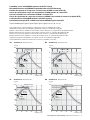
5.7.2 Dimensioning with ABB ACS800
converters with DTC control
The loadability curves presented in Figures 4a - 4d are valid
for ABB ACS800 converters with uncontrolled DC-voltage
and DTC-control. The figures show the approximate
maximum continuous output torque of the motors as a
function of supply frequency. The output torque is given
as a percentage of the nominal torque of the motor. The
values are indicative and exact values are available on
request.
NOTE!
The maximum speed of the motor must not be
exceeded!
EN-12 ABB Motors and Generators | Low voltage motor manual 01-2009

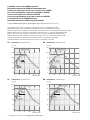
5.7.3 Dimensioning with ABB ACS550
converters
The loadability curves presented in Figures 5a - 5d are
valid for ABB ACS550 series converters. The figures show
the approximate maximum continuous output torque of
the motors as a function of supply frequency. The output
torque is given as a percentage of the nominal torque of
the motor. The values are indicative and exact values are
available on request.
NOTE!
The maximum speed of the motor must not be
exceeded!
5.7.4 Dimensioning with other voltage
source PWM-type converters
For other converters, which have uncontrolled DC
voltage and minimum switching frequency of 3 kHz,
the dimensioning instructions of ACS550 can be used
as guidelines, but it shall be noted, that the actual
thermal loadability can also be lower. Please contact the
manufacturer of the converter or the system supplier.
NOTE!
The actual thermal loadability of a motor may be
lower than shown by guideline curves.
5.7.5 Short time overloads
ABB motors can usually be temporarily overloaded as well
as used in intermittent duties. The most convenient method
to dimension such applications is to use the DriveSize tool.
5.8 Rating plates
The usage of ABB’s motors in variable speed applications
do not usually require additional rating plates and the
parameters required for commissioning the converter can
be found from the main rating plate. However, in some
special applications the motors can be equipped with
additional rating plates for variable speed applications and
those include following information:
- speed range
- power range
- voltage and current range
- type of torque (constant or quadratic)
- converter type and required minimum switching
frequency
5.9 Commissioning the variable
speed application
The commissioning of the variable speed application must
be done according to the instructions of the frequency
converter and local laws and regulations. The requirements
and limitations set by the application must also be taken
into account.
All parameters needed for setting the converter must be
taken from the motor rating plates. The most often needed
parameters are:
- Motor nominal voltage
- Motor nominal current
- Motor nominal frequency
- Motor nominal speed
- Motor nominal power
Note: In case of missing or inaccurate information, do not
operate the motor before ensuring correct settings!
ABB recommends using all the suitable protective features
provided by the converter to improve the safety of the
application. Converters usually provide features such as
(names and availability of features depend on manufacturer
and model of the converter):
- Minimum speed
- Maximum speed
- Acceleration and deceleration times
- Maximum current
- Maximum Torque
- Stall protection
Low voltage motor manual 01-2009 | ABB Motors and Generators EN-13

6. Maintenance
WARNING
Voltage may be connected at standstill inside the
terminal box for heating elements or direct winding
heating.
WARNING
The capacitor in single-phase motors can retain a
charge that appears across the motor terminals, even
when the motor has reached standstill.
WARNING
A motor with frequency converter supply may
energize even if the motor is at standstill.
6.1 General inspection
1. Inspect the motor at regular intervals, at least once a
year. The frequency of checks depends on, for example,
the humidity level of the ambient air and on the local
weather conditions. This can initially be determined
experimentally and must then be strictly adhered to.
2. Keep the motor clean and ensure free ventilation
airflow. If the motor is used in a dusty environment,
the ventilation system must be regularly checked and
cleaned.
3. Check the condition of shaft seals (e.g. V-ring or radial
seal) and replace if necessary.
4. Check the condition of connections and mounting and
assembly bolts.
5. Check the bearing condition by listening for any unusual
noise, vibration measurement, bearing temperature,
inspection of spent grease or SPM bearing monitoring.
Pay special attention to bearings when their calculated
rated life time is coming to an end.
When signs of wear are noticed, dismantle the motor,
check the parts and replace if necessary. When bearings
are changed, replacement bearings must be of the same
type as those originally fitted. The shaft seals have to be
replaced with seals of the same quality and characteristics
as the originals when changing bearings.
In the case of the IP 55 motor and when the motor
has been delivered with a plug closed, it is advisable to
periodically open the drain plugs in order to ensure that
the way out for condensation is not blocked and allows
condensation to escape from the motor. This operation
must be done when the motor is at a standstill and has
been made safe to work on.
6.1.1 Standby motors
If the motor is in standby for a longer period of time on
a ship or in other vibrating environment the following
measures have to be taken:
1. The shaft must be rotated regularly every 2 weeks (to
be reported) by means of start up of the system. In case
a start up is not possible, due to any reason, at least
the shaft has to be turned by hand in order to achieve
a different position once a week. Vibrations caused by
other vessel's equipment will cause bearing pitting which
should be minimized by regular operation / hand turning.
2. The bearing must be greased while rotating the shaft
every year (to be reported). If the motor has been
provided with roller bearing at the driven end the
transport lock to be removed before rotating the shaft.
The transport locking must be remounted in case of
transportation.
3. All vibrations must be avoided to prevent a bearing from
failuring. All instructions in the motor instruction manual
for commissioning and maintenance have to be followed
additionally. The warranty will not cover the winding and
bearing damages if these instructions have not been
followed.
6.2 Lubrication
WARNING
Beware of all rotating parts!
WARNING
Grease can cause skin irritation and eye
inflammation. Follow all safety precautions specified
by the manufacturer.
Bearing types are specified in the respective product
catalogs and on the rating plate of all motors except
smaller frame sizes.
Reliability is a vital issue for bearing lubrication intervals.
ABB uses mainly the L
1
-principle (i.e. that 99% of the
motors are certain to make the life time) for lubrication.
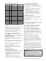
6.2.1 Machines with permanently
greased bearings
Bearings are usually permanently greased bearings of 1Z,
2Z, 2RS or equivalent types.
As a guide, adequate lubrication for sizes up to 250 can be
achieved for the following duration, according to L
10
.
EN-14 ABB Motors and Generators | Low voltage motor manual 01-2009

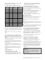
Duty hours for permanently greased bearings at ambient
temperatures of 25 and 40° C are:
Lubrication intervals according to L
10
principle
Frame size Poles
Duty hours
at 25° C
Duty hours
at 40° C
56-63 2-8 40 000 40 000
71 2 40 000 40 000
71 4-8 40 000 40 000
80-90 2 40 000 40 000
80-90 4-8 40 000 40 000
100-112 2 40 000 32 000
100-112 4-8 40 000 40 000
132 2 40 000 27 000
132 4-8 40 000 40 000
160 2 40 000 36 000
160 4-8 40 000 40 000
180 2 38 000 38 000
180 4-8 40 000 40 000
200 2 27 000 27 000
200 4-8 40 000 40 000
225 2 23 000 18 000
225 4-8 40 000 40 000
250 2 16 000 13 000
250 4-8 40 000 39 000
Data valid at 50 Hz, for 60 Hz reduce values for 20 %.
These values are valid for permitted load values given in
the product catalog. Depending on application and load
conditions, see the applicable product catalog or contact
ABB.
Operation hours for vertical motors are half of the above
values.
6.2.2 Motors with regreasable bearings
Lubrication information plate and general lubrication
advice
If the machine is equipped with a lubrication information
plate, follow the given values.
On the lubrication information plate, greasing intervals
regarding mounting, ambient temperature and rotational
speed are defined.
During the first start or after a bearing lubrication a
temporary temperature rise may appear, approximately 10
to 20 hours.
Some motors may be equipped with a collector for old
grease. Follow the special instructions given for the
equipment.
A. Manual lubrication
Regreasing while the motor is running
– Remove grease outlet plug or open closing valve if fitted.
– Be sure that the lubrication channel is open
– Inject the specified amount of grease into the bearing.
– Let the motor run for 1-2 hours to ensure that all excess
grease is forced out of the bearing. Close the grease
outlet plug or closing valve if fitted.
Regreasing while the motor is at a standstill
If it is not possible to regrease the bearings while the
motors are running, lubrication can be carried out while the
machine is at a standstill.
– In this case use only half the quantity of grease and then
run the motor for a few minutes at full speed.
– When the motor has stopped, apply the rest of the
specified amount of grease to the bearing.
– After 1-2 running hours close the grease outlet plug or
closing valve if fitted.
B. Automatic lubrication
The grease outlet plug must be removed permanently with
automatic lubrication or open closing valve if fitted.
ABB recommends only the use of electromechanical
systems.
The amount of grease per lubrication interval stated in the
table should be multiplied by four if an automatic regreasing
system is used.
When 2-pole motors are automatically regreased, the note
concerning lubricant recommendations for 2-pole motors in
the Lubricants chapter should be followed.
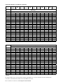
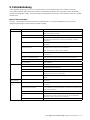
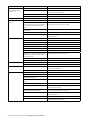
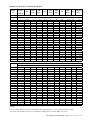
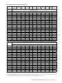
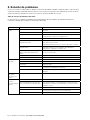
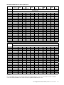
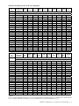
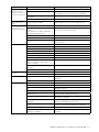
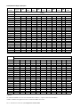
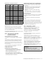
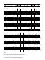
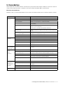
6.2.3 Lubrication intervals and amounts
As a guide, adequate lubrication for motors with
regreasable bearings can be achieved for the following
duration, according to L
1
. For duties with higher ambient
temperatures please contact ABB. The formula to change
the L
1
values roughly to L
10
values: L
10
= 2.7 x L
1
.
Lubrication intervals for vertical machines are half of the
values shown in the table below.
The lubrication intervals are based on an ambient
temperature +25°C. An increase in the ambient
temperature raises the temperature of the bearings
correspondingly. The values should be halved for a 15°C
increase and may be doubled for a 15°C decrease.
In variable speed operation (i.e. frequency converter supply)
it is necessary to measure the bearing temperature for
the whole duty range and if exceeds 80°C, the lubrication
intervals should be halved for a 15°C increase in bearing
temperature. If the motor is operated at high speeds, it is
also possible to utilize so called high speed greases, see
chapter 6.2.4.
WARNING
The maximum operating temperature of the grease
and bearings, +110°C, must not be exceeded.
The designed maximum speed of the motor must
not be exceeded.
Low voltage motor manual 01-2009 | ABB Motors and Generators EN-15

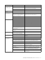
Lubrication intervals according to L
1
principle
Frame
size
Amount
of grease
g/bearing
kW
3600
r/min
3000
r/min
kW
1800
r/min
1500
r/min
kW
1000
r/min
kW
500-900
r/min
Ball bearings
Lubrication intervals in duty hours
112 10 all 10000 13000 all 18000 21000 all 25000 all 28000
132 15 all 9000 11000 all 17000 19000 all 23000 all 26500
160 25 ≤ 18,5 9000 12000 ≤ 15 18000 21500 ≤ 11 24000 all 24000
160 25 > 18,5 7500 10000 > 15 15000 18000 > 11 22500 all 24000
180 30 ≤ 22 7000 9000 ≤ 22 15500 18500 ≤ 15 24000 all 24000
180 30 > 22 6000 8500 > 22 14000 17000 > 15 21000 all 24000
200 40 ≤ 37 5500 8000 ≤ 30 14500 17500 ≤ 22 23000 all 24000
200 40 > 37 3000 5500 > 30 10000 12000 > 22 16000 all 20000
225 50 ≤ 45 4000 6500 ≤ 45 13000 16500 ≤ 30 22000 all 24000
225 50 > 45 1500 2500 > 45 5000 6000 > 30 8000 all 10000
250 60 ≤ 55 2500 4000 ≤ 55 9000 11500 ≤ 37 15000 all 18000
250 60 > 55 1000 1500 > 55 3500 4500 > 37 6000 all 7000
280
1)
60 all 2000 3500 - - - - - - -
280
1)
60 - - - all 8000 10500 all 14000 all 17000
280 35 all 1900 3200 - - - -
280 40 - - all 7800 9600 all 13900 all 15000
315 35 all 1900 3200 - - - -
315 55 -
-
all 5900 7600 all 11800 all 12900
355 35 all 1900 3200 - - - -
355 70 -
-
all 4000 5600 all 9600 all 10700
400 40 all 1500 2700 - - - -
400 85 - - all 3200 4700 all 8600 all 9700
450 40 all 1500 2700 - - - -
450 95 - - all 2500 3900 all 7700 all 8700
Roller bearings
Lubrication intervals in duty hours
160 25 ≤ 18,5 4500 6000 ≤ 15 9000 10500 ≤ 11 12000 all 12000
160 25 > 18,5 3500 5000 > 15 7500 9000 > 11 11000 all 12000
180 30 ≤ 22 3500 4500 ≤ 22 7500 9000 ≤ 15 12000 all 12000
180 30 > 22 3000 4000 > 22 7000 8500 > 15 10500 all 12000
200 40 ≤ 37 2750 4000 ≤ 30 7000 8500 ≤ 22 11500 all 12000
200 40 > 37 1500 2500 > 30 5000 6000 > 22 8000 all 10000
225 50 ≤ 45 2000 3000 ≤ 45 6500 8000 ≤ 30 11000 all 12000
225 50 > 45 750 1250 > 45 2500 3000 > 30 4000 all 5000
250 60 ≤ 55 1000 2000 ≤ 55 4500 5500 ≤ 37 7500 all 9000
250 60 > 55 500 750 > 55 1500 2000 > 37 3000 all 3500
280
1)
60 all 1000 1750 - - - - - - -
280
1)
70 - - - all 4000 5250 all 7000 all 8500
280 35 all 900 1600 - - - -
280 40 - - all 4000 5300 all 7000 all 8500
315 35 all 900 1600 - - - -
315 55
- -
all 2900 3800 all 5900 all 6500
355 35 all 900 1600 - - - -
355 70
- -
all 2000 2800 all 4800 all 5400
400 40 all - 1300 - - - -
400 85 - - all 1600 2400 all 4300 all 4800
450 40 all - 1300 - - - -
450 95 - - all 1300 2000 all 3800 all 4400
1) M3AA
For motors M4BP 160 to 250 the interval may be increased by 30 %, up to a maximum of three calendar years.
The values in table above are valid also for sizes M4BP 280 to 355.
EN-16 ABB Motors and Generators | Low voltage motor manual 01-2009

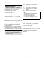
6.2.4 Lubricants
WARNING
Do not mix different types of grease.
Incompatible lubricants may cause bearing damage.
When regreasing, use only special ball bearing grease with
the following properties:
– good quality grease with lithium complex soap and with
mineral- or PAO-oil
– base oil viscosity 100-160 cST at 40°C
– consistency NLGI grade 1.5 - 3 *)
– temperature range -30°C - +120°C, continuously.
*) For vertical mounted motors or in hot conditions a stiffer
end of scale is recommended.
The above mentioned grease specification is valid if the
ambient temperature is above -30°C or below +55°C, and
the bearing temperature is below 110°C; otherwise consult
ABB regarding suitable grease.
Grease with the correct properties is available from all the
major lubricant manufacturers.
Admixtures are recommended, but a written guarantee
must be obtained from the lubricant manufacturer,
especially concerning EP admixtures, that admixtures do
not damage bearings or the properties of lubricants at the
operating temperature range.
WARNING
Lubricants containing EP admixtures are not
recommended in high bearing temperatures in frame
sizes 280 to 450.
The following high performance greases can be used:
- Esso Unirex N2 or N3 (lithium complex base)
- Mobil Mobilith SHC 100 (lithium complex base)
- Shell Gadus S5 V 100 2 (lithium complex base)
- Klüber Klüberplex BEM 41-132 (special lithium
base)
- FAG Arcanol TEMP110 (lithium complex base)
- Lubcon Turmogrease L 802 EP PLUS
(special lithium base)
- Total Multiplex S 2 A (lithium complex base)
NOTE!
Always use high speed grease for high speed 2-pole
machines where the speed factor is higher than
480,000 (calculated as Dm x n where Dm = average
bearing diameter, mm; n = rotational speed, r/min).
The high speed grease is also used in motor types
M2CA, M2FA, M2CG and M2FG, frame sizes 355 to
400 2-pole machines.
The following greases can be used for high speed cast iron
motors but not mixed with lithium complex greases:
- Klüber Klüber Quiet BQH 72-102 (polyurea base)
- Lubcon Turmogrease PU703 (polyurea base)
If other lubricants are used;
Check with the manufacturer that the qualities correspond
to those of the above mentioned lubricants. The lubrication
interval are based on the listed high performance greases
above. Using other greases can reduce the interval.
If the compatibility of the lubricant is uncertain, contact
ABB.
Low voltage motor manual 01-2009 | ABB Motors and Generators EN-17

7. After Sales Support
7.1 Spare parts
When ordering spare parts, the motor serial number, full
type designation and product code, as stated on the rating
plate, must be specified.
For more information, please visit our web site
www.abb.com/partsonline.
7.2 Rewinding
Rewinding should always be carried out by qualified repair
shops.
Smoke venting and other special motors should not be
rewound without first contacting ABB.
7.3 Bearings
Special care should be taken with the bearings. These
must be removed using pullers and fitted by heating or
using special tools for the purpose.
Bearing replacement is described in detail in a separate
instruction leaflet available from the ABB Sales Office.
8. Environmental requirements
8.1 Noise levels
Most of ABB’s motors have a sound pressure level not
exceeding 82 dB(A) at 50 Hz .
Values for specific machines can be found in the relevant
product catalogues. At 60 Hz sinusoidal supply the values
are approximately 4 dB(A) higher compared to 50 Hz
values in product catalogues.
For sound pressure levels at frequency converter supply,
please contact ABB.
Sound pressure levels for all machines having separate
cooling systems and for series M2F*/M3F*, M2L*/M3L*,
M2R*/M3R*, M2BJ/M3BJ and M2LJ/M3LJ are indicated in
separate additional manuals.
EN-18 ABB Motors and Generators | Low voltage motor manual 01-2009

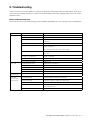
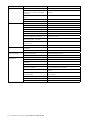
9. Troubleshooting
These instructions do not cover all details or variations in equipment nor provide for every possible condition to be met in
connection with installation, operation or maintenance. Should additional information required, please contact the nearest
ABB Sales Office.
Motor troubleshooting chart
Your motor service and any troubleshooting must be handled by qualified persons who have proper tools and equipment.
TROUBLE CAUSE WHAT TO DO
Motor fails to start Blown fuses Replace fuses with proper type and rating.
Overload trips Check and reset overload in starter.
Improper power supply Check to see that power supplied agrees with motor rating plate and
load factor.
Improper line connections Check connections against diagram supplied with motor.
Open circuit in winding or control switch Indicated by humming sound when switch is closed. Check for loose
wiring connections.
Also ensure that all control contacts are closing.
Mechanical failure Check to see if motor and drive turn freely. Check bearings and
lubrication.
Short circuited stator
Poor stator coil connection
Indicated by blown fuses. Motor must be rewound. Remove end
shields, locate fault.
Rotor defective Look for broken bars or end rings.
Motor may be overloaded Reduce load.
Motor stalls One phase may be open Check lines for open phase.
Wrong application Change type or size. Consult equipment supplier.
Overload Reduce load.
Low voltage Ensure the rating plate voltage is maintained. Check connection.
Open circuit Fuses blown, check overload relay, stator and push buttons.
Motor runs and
then dies down
Power failure Check for loose connections to line, to fuses and to control.
Motor does
not come up to
nominal speed
Not applied properly Consult equipment supplier for proper type.
Voltage too low at motor terminals
because of line drop
Use higher voltage or transformer terminals or reduce load. Check
connections. Check conductors for proper size.
Starting load too high Check the start load of the motor.
Broken rotor bars or loose rotor Look for cracks near the rings. A new rotor may be required, as repairs
are usually temporary.
Open primary circuit Locate fault with testing device and repair.
Low voltage motor manual 01-2009 | ABB Motors and Generators EN-19

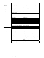
TROUBLE CAUSE WHAT TO DO
Motor takes too long to
accelerate and/or draws
high current
Excessive load Reduce load.
Low voltage during start Check for high resistance. Make sure that adequate cable
size is used.
Defective squirrel cage rotor Replace with new rotor.
Applied voltage too low Correct power supply.
Wrong rotation direction Wrong sequence of phases Reverse connections at motor or at switchboard.
Motor overheats while
running
Overload Reduce load.
Frame or ventilation openings may
be full of dirt and prevent proper
ventilation of motor
Open vent holes and check for a continuous stream of air
from the motor.
Motor may have one phase open Check to make sure that all leads are well connected.
Grounded coil Motor must be rewound
Unbalanced terminal voltage Check for faulty leads, connections and transformers.
Motor vibrates Motor misaligned Realign.
Weak support Strengthen base.
Coupling out of balance Balance coupling.
Driven equipment unbalanced Rebalance driven equipment.
Defective bearings Replace bearings.
Bearings not in line Repair motor.
Balancing weights shifted Rebalance motor.
Contradiction between balancing of
rotor and coupling (half key - full key)
Rebalance coupling or motor.
Polyphase motor running single phase Check for open circuit.
Excessive end play Adjust bearing or add shim.
Scraping noise Fan rubbing end shield or fan cover Correct fan mounting.
Loose on bedplate Tighten holding bolts.
Noisy operation Air gap not uniform Check and correct end shield fits or bearing fits.
Rotor unbalance Rebalance rotor.
Hot bearings Bent or sprung shaft Straighten or replace shaft.
Excessive belt pull Decrease belt tension.
Pulleys too far away from shaft shoulder Move pulley closer to motor bearing.
Pulley diameter too small Use larger pulleys.
Misalignment Correct by realignment of the drive.
Insufficient grease Maintain proper quality and amount of grease in bearing.
Deterioration of grease or lubricant
contaminated
Remove old grease, wash bearings thoroughly in kerosene
and replace with new grease.
Excess lubricant Reduce quantity of grease, bearing should not be more than
half full.
Overloaded bearing Check alignment, side and end thrust.
Broken ball or rough races Replace bearing, clean housing thoroughly first.
EN-20
ABB Motors and Generators | Low voltage motor manual 01-2009
Seite wird geladen ...
Seite wird geladen ...
Seite wird geladen ...
Seite wird geladen ...
Seite wird geladen ...
Seite wird geladen ...
Seite wird geladen ...
Seite wird geladen ...
Seite wird geladen ...
Seite wird geladen ...
Seite wird geladen ...
Seite wird geladen ...
Seite wird geladen ...
Seite wird geladen ...
Seite wird geladen ...
Seite wird geladen ...
Seite wird geladen ...
Seite wird geladen ...
Seite wird geladen ...
Seite wird geladen ...
Seite wird geladen ...
Seite wird geladen ...
Seite wird geladen ...
Seite wird geladen ...
Seite wird geladen ...
Seite wird geladen ...
Seite wird geladen ...
Seite wird geladen ...
Seite wird geladen ...
Seite wird geladen ...
Seite wird geladen ...
Seite wird geladen ...
Seite wird geladen ...
Seite wird geladen ...
Seite wird geladen ...
Seite wird geladen ...
Seite wird geladen ...
Seite wird geladen ...
Seite wird geladen ...
Seite wird geladen ...
Seite wird geladen ...
Seite wird geladen ...
Seite wird geladen ...
Seite wird geladen ...
Seite wird geladen ...
Seite wird geladen ...
Seite wird geladen ...
Seite wird geladen ...
Seite wird geladen ...
Seite wird geladen ...
Seite wird geladen ...
Seite wird geladen ...
Seite wird geladen ...
Seite wird geladen ...
Seite wird geladen ...
Seite wird geladen ...
Seite wird geladen ...
Seite wird geladen ...
Seite wird geladen ...
Seite wird geladen ...
Seite wird geladen ...
Seite wird geladen ...
Seite wird geladen ...
Seite wird geladen ...
Seite wird geladen ...
Seite wird geladen ...
Seite wird geladen ...
Seite wird geladen ...
Seite wird geladen ...
Seite wird geladen ...
Seite wird geladen ...
Seite wird geladen ...
Seite wird geladen ...
Seite wird geladen ...
Seite wird geladen ...
Seite wird geladen ...
Seite wird geladen ...
Seite wird geladen ...
Seite wird geladen ...
Seite wird geladen ...
Seite wird geladen ...
Seite wird geladen ...
Seite wird geladen ...
Seite wird geladen ...
Seite wird geladen ...
Seite wird geladen ...
Seite wird geladen ...
Seite wird geladen ...
Seite wird geladen ...
Seite wird geladen ...
Seite wird geladen ...
Seite wird geladen ...
Seite wird geladen ...
Seite wird geladen ...
Seite wird geladen ...
Seite wird geladen ...
Seite wird geladen ...
Seite wird geladen ...
Seite wird geladen ...
Seite wird geladen ...
Seite wird geladen ...
Seite wird geladen ...
Seite wird geladen ...
Seite wird geladen ...
Seite wird geladen ...
Seite wird geladen ...
Seite wird geladen ...
Seite wird geladen ...
Seite wird geladen ...
Seite wird geladen ...
Seite wird geladen ...
Seite wird geladen ...
Seite wird geladen ...
Seite wird geladen ...
Seite wird geladen ...
Seite wird geladen ...
Seite wird geladen ...
Seite wird geladen ...
Seite wird geladen ...
Seite wird geladen ...
Seite wird geladen ...
Seite wird geladen ...
Seite wird geladen ...
Seite wird geladen ...
Seite wird geladen ...
Seite wird geladen ...
Seite wird geladen ...
Seite wird geladen ...
Seite wird geladen ...
Seite wird geladen ...
Seite wird geladen ...
Seite wird geladen ...
Seite wird geladen ...
Seite wird geladen ...
Seite wird geladen ...
Seite wird geladen ...
Seite wird geladen ...
Seite wird geladen ...
Seite wird geladen ...
Seite wird geladen ...
-
 1
1
-
 2
2
-
 3
3
-
 4
4
-
 5
5
-
 6
6
-
 7
7
-
 8
8
-
 9
9
-
 10
10
-
 11
11
-
 12
12
-
 13
13
-
 14
14
-
 15
15
-
 16
16
-
 17
17
-
 18
18
-
 19
19
-
 20
20
-
 21
21
-
 22
22
-
 23
23
-
 24
24
-
 25
25
-
 26
26
-
 27
27
-
 28
28
-
 29
29
-
 30
30
-
 31
31
-
 32
32
-
 33
33
-
 34
34
-
 35
35
-
 36
36
-
 37
37
-
 38
38
-
 39
39
-
 40
40
-
 41
41
-
 42
42
-
 43
43
-
 44
44
-
 45
45
-
 46
46
-
 47
47
-
 48
48
-
 49
49
-
 50
50
-
 51
51
-
 52
52
-
 53
53
-
 54
54
-
 55
55
-
 56
56
-
 57
57
-
 58
58
-
 59
59
-
 60
60
-
 61
61
-
 62
62
-
 63
63
-
 64
64
-
 65
65
-
 66
66
-
 67
67
-
 68
68
-
 69
69
-
 70
70
-
 71
71
-
 72
72
-
 73
73
-
 74
74
-
 75
75
-
 76
76
-
 77
77
-
 78
78
-
 79
79
-
 80
80
-
 81
81
-
 82
82
-
 83
83
-
 84
84
-
 85
85
-
 86
86
-
 87
87
-
 88
88
-
 89
89
-
 90
90
-
 91
91
-
 92
92
-
 93
93
-
 94
94
-
 95
95
-
 96
96
-
 97
97
-
 98
98
-
 99
99
-
 100
100
-
 101
101
-
 102
102
-
 103
103
-
 104
104
-
 105
105
-
 106
106
-
 107
107
-
 108
108
-
 109
109
-
 110
110
-
 111
111
-
 112
112
-
 113
113
-
 114
114
-
 115
115
-
 116
116
-
 117
117
-
 118
118
-
 119
119
-
 120
120
-
 121
121
-
 122
122
-
 123
123
-
 124
124
-
 125
125
-
 126
126
-
 127
127
-
 128
128
-
 129
129
-
 130
130
-
 131
131
-
 132
132
-
 133
133
-
 134
134
-
 135
135
-
 136
136
-
 137
137
-
 138
138
-
 139
139
-
 140
140
-
 141
141
-
 142
142
-
 143
143
-
 144
144
-
 145
145
-
 146
146
-
 147
147
-
 148
148
-
 149
149
-
 150
150
-
 151
151
-
 152
152
-
 153
153
-
 154
154
-
 155
155
-
 156
156
-
 157
157
-
 158
158
-
 159
159
-
 160
160


ABB M2F series Installation, Operation & Maintenance Manual
- Typ
- Installation, Operation & Maintenance Manual
in anderen Sprachen
- English: ABB M2F series
- français: ABB M2F series
- español: ABB M2F series
- italiano: ABB M2F series
- português: ABB M2F series
- svenska: ABB M2F series
- suomi: ABB M2F series
Verwandte Artikel
Andere Dokumente
-
LevelOne Media Converters Installationsanleitung
-
Sulzer Low Voltage Electric Motors MT and MM Maintenance Manual
-
Homa KX...H series Original Instruction Manual
-
 Elektror S-HP 380/30 Operating And Assembly Instructions Manual
-
WEG MAS Getriebemotoren - Montageanleitung / Geared Motors - Mounting Benutzerhandbuch
-
Kollmorgen AKMH3 Benutzerhandbuch
-
EHEIM FLOW12000 Bedienungsanleitung
-
Kollmorgen AKM3 Benutzerhandbuch
-
Sincro FB2 Use and Maintenance Manual
-
