WEG MAS Getriebemotoren - Montageanleitung / Geared Motors - Mounting Benutzerhandbuch
- Kategorie
- Spielzeuge
- Typ
- Benutzerhandbuch

Montageanleitung
inklusive Hinweise zu Betrieb und Wartung
Mounting Instruction
Information about operation and maintenance is included
MAS
®
- Getriebe und Getriebemotoren
MAS
®
- Gear units and geared motors
ATEX included
BA27 MAS, ATEX
01/2017
Deutsch – English
Originaldokument: Deutsch
Original documentation: German

Montageanleitung für MAS
®
- Getriebe und Getriebemotoren
Mounting Instruction for MAS
®
- Gear units and geared motors
Watt Drive Antriebstechnik GmbH ·A-2753 Markt Piesting ·Wöllersdorfer Str. 68 ·Phone: +43(0)2633 404-0 · Fax: +43(0)2633 404-220 · Mail: watt@wattdrive.com · Web: www.wattdrive.com
2
Inhaltsverzeichnis / Contents
1
Allgemeines / General ................................................................................................................................................................ 4
Sicherheits- und Hinweiszeichen / Safety and information markings ................................................................................... 4
Allgemeine Informationen / General information .................................................................................................................. 4
Haftungsausschluss / Exclusion of liability ........................................................................................................................... 5
Hinweis auf Urheber und Schutzrecht / Indication of copyright and protective right ............................................................. 5
2
Allgemeine Sicherheit / General safety .................................................................................................................................... 6
3
Beschreibung des Getriebes, Getriebemotors / Gear unit, Geared motor description ........................................................ 7
Typenschild / Nameplate ...................................................................................................................................................... 7
Typenbezeichnung / Type designation ................................................................................................................................. 7
4
Transport .................................................................................................................................................................................. 10
5
Lagerung / Storage .................................................................................................................................................................. 11
6
Getriebeaufbau / Gear unit construction ............................................................................................................................... 12
Prinzipieller Aufbau – Stirnradgetriebe H / Basic design principles helical gear unit H ...................................................... 12
Prinzipieller Aufbau – Aufsteckgetriebe A / Basic design principles shaft mounted gear unit A ......................................... 13
Prinzipieller Aufbau – Flachgetriebe F / Basic design principles parallel shaft gear unit F ................................................. 14
Prinzipieller Aufbau - Schneckengetriebe S / Basic design principles helical worm gear unit S ......................................... 15
Prinzipieller Aufbau – Kegelstirnradgetriebe K / Basic design principles helical bevel gear unit K ..................................... 16
Prinzipieller Aufbau – Kegelflachgetriebe C / Basic design principles angle parallel shaft gear unit C .............................. 17
7
Mechanische Installation / Mechanical installation ............................................................................................................... 18
Vorarbeiten Getriebe / Preparatory work gear unit ............................................................................................................. 18
Vorarbeiten Motor / Preparatory work motor ...................................................................................................................... 19
Aufstellen des Getriebes, Getriebemotors / Setting up the gear unit, geared motor .......................................................... 21
8
Checkliste – Getriebe / Check list – Gear unit ....................................................................................................................... 33
9
Checkliste – Motor / Check list – Motor ................................................................................................................................. 34
10
Inbetriebnahme / Startup ......................................................................................................................................................... 35
Elektrischer Anschluss des Motor / Electrical connecting the motor .................................................................................. 35
Drehrichtung / Direction of rotation ..................................................................................................................................... 35
Ölstand des gelieferten Getriebes / Oil level in the gear unit as delivered ......................................................................... 35
11
Betrieb / Operation ................................................................................................................................................................... 36
12
Betriebsstörungen / Malfunction ............................................................................................................................................ 36
13
Inspektion und Wartung / Inspection and maintenance ....................................................................................................... 37
Inspektions- und Wartungsintervalle / Inspection and maintenance intervals .................................................................... 38
Inspektions- und Wartungsarbeiten Getriebe / Inspection and maintenance work on gear unit ......................................... 39
14
Schmierstoffe / Lubricants ...................................................................................................................................................... 41
15
Bauformen und Schmierstoffmengen / Mounting positions and lubricant capacity ......................................................... 42
Stirnradgetriebe H / Helical gear units H ............................................................................................................................ 42
Einstufige Stirnradgetriebe H / Single stage helical gear units H ....................................................................................... 43
Aufsteckgetriebe A / Shaft mounted gear units A ............................................................................................................... 44
Flachgetriebe F / Parallel shaft gear units F ....................................................................................................................... 45
Kegelstirnradgetriebe K40 - K75 / Helical bevel gear units K40 - K75 ............................................................................... 46
Kegelstirnradgetriebe K77 - K139 / Helical bevel gear units K77 - K139 ........................................................................... 47
Stirnradschneckengetriebe S / Helical worm gear units S .................................................................................................. 48
Kegelflachgetriebe C / Angle parallel shaft gear units C .................................................................................................... 49

Montageanleitung für MAS
®
- Getriebe und Getriebemotoren
Mounting Instruction for MAS
®
- Gear units and geared motors
Watt Drive Antriebstechnik GmbH ·A-2753 Markt Piesting ·Wöllersdorfer Str. 68 ·Phone: +43(0)2633 404-0 · Fax: +43(0)2633 404-220 · Mail: watt@wattdrive.com · Web: www.wattdrive.com
3
Ölstandskontrolle bei Getrieben mit Ölstandsschraube in vertikaler Bauform / Oil level control of gear units with oil level
plug at vertical mounting position ......................................................................................................................................... 50
16
Klemmenanschluss / Terminal board connection ................................................................................................................. 51
17
Optionale Motorzusatzeinrichtungen / Optional motor devices .......................................................................................... 53
Stillstandsheizung / Anti-condensation heating .................................................................................................................. 53
Kondenswasserbohrung / Drain ......................................................................................................................................... 53
Fremdlüfter / Forced cooling .............................................................................................................................................. 54
Temperaturwächter Bimetallschalter “Öffner” (TH) / Temperature controller Bimetal switch “NC contact” (TH) ................ 54
PTC Kaltleitertemperaturfühler (TF) / PTC Thermistor protection (TF) .............................................................................. 54
Bremse / Brake .................................................................................................................................................................. 55
Drehgeber / Encoder .......................................................................................................................................................... 58
18
Tabelle für Schraubenanzugsmomente / Table of Tightening Torques .............................................................................. 59
19
Entsorgung / Disposal ............................................................................................................................................................. 59
20
Einbauerklärung / Declaration of Incorporation .................................................................................................................... 61
21
EU-Konformitätserklärung ATEX 2014/34/EU / EU Declaration of Conformity ATEX 2014/34/EU ..................................... 63
22
EU-Konformitätserklärung Niederspannungsrichtlinie 2014/35/EU / EU-Declaration of Conformity Low Voltage
Directive 2014/35/EU ................................................................................................................................................................ 65

Montageanleitung für MAS
®
- Getriebe und Getriebemotoren
Mounting Instruction for MAS
®
- Gear units and geared motors
Watt Drive Antriebstechnik GmbH ·A-2753 Markt Piesting ·Wöllersdorfer Str. 68 ·Phone: +43(0)2633 404-0 · Fax: +43(0)2633 404-220 · Mail: watt@wattdrive.com · Web: www.wattdrive.com
4
1 Allgemeines / General
Sicherheits- und Hinweiszeichen / Safety and information markings
Diese Sicherheits- und Warnhinweise sind unbedingt zu
beachten!
GEFAHR !
Warnung vor elektrischer oder mechanischer Gefahr.
ATEX !
Wichtige Hinweise zum Explosionsschutz.
VORSICHT !
Wichtige Anweisung für sicheren und störungsfreien
Betrieb.
All safety and warning instructions must be followed
without exception!
WARNING !
Warning of electrical or mechanical danger.
ATEX !
Important information on explosion protection.
ATTENTION !
Important instructions for safe and trouble-free operation.
Allgemeine Informationen / General information
Die vorliegende Montageanleitung (MA) ist Bestandteil der
Getriebelieferung und muss bevor Sie mit dem Getriebe
arbeiten gelesen werden. Die Anweisungen dieser MA sollten
unbedingt eingehalten werden. Bewahren Sie die MA in der
Nähe des Getriebes auf.
Für Schäden bzw. Betriebsstörungen, die durch
Nichtbeachtung dieser MA resultieren, wird keine Haftung
übernommen.
Der Hersteller behält sich in Sinne einer Weiterentwicklung das
Recht vor, an den einzelnen Bauteilen bzw. Baugruppen
Änderungen vorzunehmen, die unter Beibehaltung der
wesentlichen Merkmale zur Verbesserung des Produkts für
sinnvoll erachtet werden.
Schutzart:
Die Getriebe entsprechen der Schutzart IP 65.
Motore sind mindestens in Schutzart IP 55 (siehe Typenschild)
ausgeführt.
Bestimmungsgemäße Verwendung:
Die Getriebe / Getriebemotoren sind ausschließlich zur
Erzeugung einer definierten Drehbewegung innerhalb von
Maschinen und Anlagen bestimmt. Die Getriebe entsprechen
so weit als möglich den grundlegenden Anforderungen der
Maschinerichtlinie 2006/42/EG.
Eine andere oder darüber hinausgehende Benutzung gilt als
nicht bestimmungsgemäß. Für hieraus resultierende Schäden
haftet allein der Benutzer/Betreiber der Maschine / Anlage.
Die Angaben in dieser Montageanleitung, auf dem Typenschild
sowie in der sonstigen technischen Dokumentation sind zu
beachten und einzuhalten.
This Mounting Instruction (MI) is part of the gear unit as
supplied and must be read carefullybefore working with the
gear unit. The instructions in the MI must be followed. Keep the
MI close to the gear unit.
We assume no liability for damages or disruptions of operations
resulting from the failure to observe this MI.
In order to develop the product further, the producer reserves
the right to make modifications to the individual components or
assemblies that are believed to be useful to improve the
product, while maintaining its essential characteristics.
Protection class:
The gears are in accordance with Protection Class IP 65.
Motors are designed within Protection Class IP 55 at minimum
(see nameplate).
Intended use:
The gears / geared motors are exclusively assigned for the
generation of a defined rotary motion within machinery and
plants. The gears comply with the basic requirements of the
machinery directive 2006/42/EC as far as possible.
Any other use or utilisation above this is deemed to be a not
intended use. The user / operator of the machine / plant is
solely liable for damages resulting therefrom.
The details in this mounting instruction, on the nameplate as
well as in other technical documentation, are to be considered
and observed.

Montageanleitung für MAS
®
- Getriebe und Getriebemotoren
Mounting Instruction for MAS
®
- Gear units and geared motors
Watt Drive Antriebstechnik GmbH ·A-2753 Markt Piesting ·Wöllersdorfer Str. 68 ·Phone: +43(0)2633 404-0 · Fax: +43(0)2633 404-220 · Mail: watt@wattdrive.com · Web: www.wattdrive.com
5
Bestimmungsgemäße Verwendung im EX-Bereich:
Getriebe in ATEX-Ausführung entsprechen den gültigen
Normen und Vorschriften und erfüllen die Forderungen der
Richtlinie 2014/34/EU. Motore, Getriebemotoren welche nicht
für den EX-Bereich zugelassen sind, dürfen nicht eingesetzt
werden.
Die explosionsgeschützten Getriebe der Baureihen
H... Stirnradgetriebe
A... Aufsteckgetriebe
F... Flachgetriebe
S... Stirnradschneckengetriebe
K... Kegelstirnradgetriebe
C... Kegelflachgetriebe
entsprechen den Bauvorschriften der:
Gerätegruppe I, Kategorie M2 und Gerätegruppe II, Kategorie
2G, 3G (Ex-Atmosphäre Gas) und 2D, 3D (Ex-Atmosphäre
Staub).
Das Getriebe K.. 40. darf nicht im explosionsgefährdeten
Bereich eingesetzt werden.
Bestimmungsgemäße Verwendung Motor:
Die Motoren entsprechen den grundlegenden Anforderungen
der Niederspannungsrichtlinie 2014/35/EU. Sie sind sowohl für
Netzbetrieb als auch in Verbindung mit Frequenzumrichtern
konzipiert.
Die Motoren in Standardausführung sind für folgenden Betrieb
ausgelegt:
Umgebungstemperatur: -20°C (-4°F) bis +40°C
(104°F)
Aufstellungshöhen ≤ 1000m (über Meeresspiegel)
Intended use in the ex-area:
Drive units in ATEX execution meet valid standards and
specifications as well as the requirements set forth in Directive
2014/34/EU. Motors, geared motors that are not approved for
the ex-area, must not be used.
The explosion-protected gear units of series
H... Helical gear unit
A... Shaft mounted gear unit
F... Parallel shaft gear unit
S... Helical worm gear unit
K... Helical bevel gear units
C... Angle parallel shaft gear units
meet the design specifications of:
Equipment group 1, Category M2 and Equipment group II,
Category 2G, 3G (ex atmospheres gas) and 2D, 3G (ex
atmospheres dust).
The gear unit K.. 40. must not be used in areas where there is
a risk
Intended use for motors:
The motors comply with the basic requirements of the Low
Voltage Directive 2014/35/EU. They are designed for power
operating as well as operating in combination with frequency
inverters.
They are designed both for mains operation as well as in
conjunction with frequency converters.
Standard motors are designed for use at:
Ambient temperature of -20°C (-4°F) to +40°C (104°F)
Altitudes of ≤ 1,000m above sea level.of explosions.
Haftungsausschluss / Exclusion of liability
Die Beachtung der MA ist Grundvoraussetzung für den
sicheren Betrieb des Getriebes/Getriebemotors und für die
Erreichung der angegebenen Produkteigenschaften und
Leistungsmerkmale.
Für Personen-, Sach- oder Vermögensschäden, die wegen
Nichtbeachtung der MA entstehen, übernimmt der Hersteller
keine Haftung. Die Sachmängelhaftung ist in solchen Fällen
ausgeschlossen.
You must comply with the information contained in this MI to
ensure safe operation of the gear unit, geared motor and to
achieve the specified product characteristics and performance
requirements.
The producer assumes no liability for injury to people or
damage to equipment or property resulting from non-
observance of this MI. In such cases, any liability for defects is
excluded.
Hinweis auf Urheber und Schutzrecht / Indication of copyright and protective right
Alle technischen Unterlagen sind im Sinne des Urheberrechts
geschützt. Die Bearbeitung, Vervielfältigung und Verbreitung ,
von diesen, auch auszugsweise, sowie sonstiger Verwertung
sind nicht gestattet, soweit nicht ausdrücklich schriftlich
zugestanden.
All technical documents are protected in the sense of the
copyright law. The processing, reproduction and dissemination
of it, even in extracts, as well as other utilisation is not allowed,
unless it has been expressly conceded in written form.

Montageanleitung für MAS
®
- Getriebe und Getriebemotoren
Mounting Instruction for MAS
®
- Gear units and geared motors
Watt Drive Antriebstechnik GmbH ·A-2753 Markt Piesting ·Wöllersdorfer Str. 68 ·Phone: +43(0)2633 404-0 · Fax: +43(0)2633 404-220 · Mail: watt@wattdrive.com · Web: www.wattdrive.com 6
2 Allgemeine Sicherheit / General safety
Der Kunde ist verantwortlich für die fachgerechte Aufstellung
des Antriebes.
Bestätigte Eigenschaften der Antriebe sowie die Erfüllung
eventueller Garantieansprüche bedingen die Einhaltung der
Hinweise in dieser Montageanleitung.
Achten Sie darauf, niemals beschädigte Produkte in Betrieb zu
nehmen!
Lesen Sie die Montageanleitung sorgfältig, bevor Sie mit
Aufstell-, Montage- oder Wartungsarbeiten beginnen.
Die Montage, Inbetriebnahme sowie Wartungs- und
Reparaturarbeiten am Getriebe/Getriebemotor sowie an der
elektrischen Zusatzausstattung dürfen nur von qualifiziertem
Fachpersonal ausgeführt werden, unter Berücksichtigung
folgender Punkte:
Montageanleitung
Hinweisschilder am Getriebe/Getriebemotor
aller anderen zum Antrieb gehörenden
Projektierungs-unterlagen,
Inbetriebnahmeanleitungen
Anlagenspezifische Bestimmungen und Erfordernisse
aktuell gültigen nationalen und regionalen
Vorschriften über Sicherheit und Unfallverhütung.
GEFAHR !
Alle Arbeiten dürfen nur :
am stillstehenden Antrieb,
im spannungsfreien und
gegen Wiedereinschalten gesicherten Zustand vor
genommen werden.
Der Betrieb des Getriebemotors mittels Frequenzumrichter darf
nur unter Einhaltung der Angaben am Typenschild des Motors
durchgeführt werden.
ATEX !
Der Einsatz von Getrieben/Getriebemotoren kann in
explosionsfähigen Gasgemischen oder
Staubkonzentrationen in Verbindung mit heißen,
spannungsführenden und bewegten Teilen schwere oder
tödliche Verletzungen verursachen.
The customer is responsible for setting up the drive in
accordance with good engineering practices.
The instructions in this Mounting Instruction must be followed
to achieve the confirmed characteristics of the drive units and
to ensure approval in case of warranty claims.
Make certain that you never put damaged products into
operation!
Read this Mounting Instruction carefully before you begin any
setup, installation, or maintenance work.
Installation, startup, maintenance and repair work on the gear
unit / gear motor as well as on electrical accessory equipment
may only be performed by qualified technical personnel,
taking the following items into account:
Operating Instructions
Information labels/tags on the gear unit / geared motor
All other project documents, setup manuals, operating
manuals
Drive-specific specifications and requirements
belonging to the drive unit
the applicable regional and national regulations on
safety and accident prevention.
WARNING !
Work is only permitted :
on the stationary drive,
while disconnected and
prevented form being switched on again.
Operation of the drive unit by means of a frequency inverter
may only occur if the specifications shown on the motor
nameplate have been carried out.
ATEX !
The use of gear units/gear motors in gas mixtures or dust
concentrations that are capable of exploding in
combination with hot, load bearing and moving parts, can
result in death or serious injury.

Montageanleitung für MAS
®
- Getriebe und Getriebemotoren
Mounting Instruction for MAS
®
- Gear units and geared motors
Watt Drive Antriebstechnik GmbH ·A-2753 Markt Piesting ·Wöllersdorfer Str. 68 ·Phone: +43(0)2633 404-0 · Fax: +43(0)2633 404-220 · Mail: watt@wattdrive.com · Web: www.wattdrive.com
7
3 Beschreibung des Getriebes, Getriebemotors / Gear unit, Geared motor description
Typenschild / Nameplate
Alle Daten am Typenschild des Getriebes legen die Grenzen
seines bestimmungsgemäßen Gebrauchs fest. Diese Daten
sind unbedingt einzuhalten.
Weitere technische Daten, Zeichnungen entnehmen Sie Bitte
aus dem aktuellesten Getriebemotorenkatalog.
All data on the nameplate of the gear define the limits of its
intended usage. It is imperative to adhere to this data.
Please take further technical data and drawings from the latest
geared motor catalogue.
Getriebemotor / Geared motor
(Beispielhafte Darstellung / Typical appearance)
Getriebe im EX-Bereich / Gear unit in ex-area
(Beispielhafte Darstellung / Typical appearance)
Typenbezeichnung / Type designation
HU 40A … Typenbezeichnung Type designation
# 950… Getriebenummer Gear no.
0,18 kW Leistung Power
24 min
-1
Drehzahl Speed
72 Nm Drehmoment Torque
B3 Bauform Mounting position
i=55,30 Getriebeuntersetzung Gear unit ratio
II Gerätegruppe Instrument group
2 Kategorie Category
D EX - Atmosphäre EX Atmosphere
c Zündschutzart Type of ignition protection
120° Temperaturklasse bzw. max. Oberflächentemperatur Temperature class or maximum surface
Typenbezeichnung (Beispiel)
Type designation (example)
HF 70A 3B 100L-04E TH FL IG ASA 66C 3B 90S/L-04E BR20
Baureihe / Model range H (Stirnradgetriebe /
Helical gear unit)
A (Aufsteckgetriebe /
Shaft mounted gear unit)
Mögliche Getriebeausführung /
Possible gear unit execution
HU (Uniblock
®
)
HF (Flansch / Flange)
HG (Fuß / Foot)
ASA (Support+Hohlwelle / Hollow shaft)
AS (Support+Abtriebswelle / Output shaft)
ASS (Support+Schrumpfscheibe / Shrink disc)
ASZ (Support+Doppelabtriebswelle /
Double output shaft)
AFA (Flansch+Hohlwelle / Flange+Hollow shaft)
AF (Flansch+Abtriebswelle / Flange+Output sh.)
AFS (Flansch+Schrumpfscheibe /
Flange+Shrink disc)
ARA (Rührwerksausführung mit Hohlwelle /
Agitator drive with hollow shaft)
AR (Rührwerksausführung mit Abtriebswelle /
Agitator drive with output shaft)
ARS (Rührwerksaus. mit Schrumpfscheibe /
Agitator drive with shrink disc)

Montageanleitung für MAS
®
- Getriebe und Getriebemotoren
Mounting Instruction for MAS
®
- Gear units and geared motors
Watt Drive Antriebstechnik GmbH ·A-2753 Markt Piesting ·Wöllersdorfer Str. 68 ·Phone: +43(0)2633 404-0 · Fax: +43(0)2633 404-220 · Mail: watt@wattdrive.com · Web: www.wattdrive.com 8
Mögliche Getriebegrößen /
Possible gear unit sizes
40, 41, 50, 51, 55, 60, 65, 70, 80, 85,
110, 130, 133, 136
46, 56, 66, 76, 86
Zahnradstufencode /
Gear stage code
E (1-stufig, 1-stage)
A, S (2-stufig, 2- stages)
C (3-stufig, 3-stages)
D (4-stufig, 4-stages)
F (5-stufig, 5-stages)
A, S (2-stufig, 2- stages)
C (3-stufig, 3-stages)
D (4-stufig, 4-stages)
Typenbezeichnung (Beispiel)
Type designation (example)
FUA 111C 3B 112M-04E MIP KUA 75C 3A 63-04F SD
Baureihe / Model range F (Flachgetriebe /
Parallel shaft gear unit)
K (Kegelstirnradgetriebe /
Helical bevel gear unit)
Mögliche Getriebeausführung /
Possible gear unit execution
FUA (Uniblock
®
+ Hohlwelle /
Hollow shaft)
FU (Uniblock
®
+Abtriebswelle /
Output shaft)
FUS (Uniblock
®
+Schrumpfscheibe /
Shrink disc)
FUZ (Uniblock
®
+ Abtriebswelle
beidseitig / Double output shaft)
FFA (Flansch+Hohlwelle /
Flange+Hollow shaft)
FF (Flansch+Abtriebswelle /
Flange+Output sh.)
FFS (Flansch+Schrumpfscheibe /
Flange+Shrink disc)
FSA (Support+Hohlwelle /
Hollow shaft)
FS (Support+Abtriebswelle /
Output shaft)
FSS (Support+Schrumpfscheibe /
Shrink disc)
FSZ (Support+Abtriebswelle
beidseitig / Double output shaft)
FRA (Rührwerksausf.mit Hohlwelle /
Agitator drive with hollow shaft)
FR (Rührwerksausf. Abtriebswelle /
Agitator drive with output shaft)
FRS (Rührwerksaus. Mit Schrumpf-
scheibe / Agitator drive with
shrink disc)
KUA (Uniblock
®
+ Hohlwelle / Hollow shaft)
KU (Uniblock
®
+Abtriebswelle / Output shaft)
KUS (Support+Schrumpfscheibe / Shrink disc)
KUZ (Uniblock
®
+ Abtriebswelle beidseitig /
Double output shaft)
KSA (Support+Hohlwelle / Hollow shaft)
KSS (Support+Schrumpfscheibe / Shrink disc).)
KFA (Flansch+Hohlwelle / Flange+Hollow shaft)
KF (Flansch+Abtriebswelle / Flange+Output sh.)
KFS (Flansch+Schrumpfscheibe /
Flange+Shrink disc)
KRA (Rührwerksausführung mit Hohlwelle /
Agitator drive with hollow shaft)
KR (Rührwerksausführung mit Abtriebswelle /
Agitator drive with output shaft)
KRS (Rührwerksaus. mit Schrumpfscheibe /
Agitator drive with shrink disc)
Mögliche Getriebegrößen /
Possible gear unit sizes
111, 131, 137 40, 50, 60, 70, 75, 77, 80, 86, 110, 136, 139
Zahnradstufencode /
Gear stage code
111, 131:
A, S (2-stufig, 2- stages)
C (3-stufig, 3-stages)
D (4-stufig, 4-stages)
F (5-stufig, 5-stages)
137:
A (3-stufig, 3-stages)
C (4-stufig, 4-stages)
D (5-stufig, 5-stages)
40, 50, 60, 70, 75:
A (2-stufig, 2- stages)
C (3-stufig, 3-stages)
D (4-stufig, 4-stages)
77, 80, 86, 110, 136, 139:
A (3-stufig, 3-stages)
C (4-stufig, 4-stages)
D (5-stufig, 5-stages)

Montageanleitung für MAS
®
- Getriebe und Getriebemotoren
Mounting Instruction for MAS
®
- Gear units and geared motors
Watt Drive Antriebstechnik GmbH ·A-2753 Markt Piesting ·Wöllersdorfer Str. 68 ·Phone: +43(0)2633 404-0 · Fax: +43(0)2633 404-220 · Mail: watt@wattdrive.com · Web: www.wattdrive.com 9
Typenbezeichnung (Beispiel)
Type designation (example)
SSA 455A 3A 80-04E CF 130A 3C 200M/L-04E SG
Baureihe / Model range S (Stinradschneckengetriebe /
Helical worm gear unit
C (Kegelflachgetriebe /
Angle parallel shaft gear unit)
Mögliche Getriebeausführung /
Possible gear unit execution
SUA (Uniblock
®
+ Hohlwelle /
Hollow shaft)
SU (Uniblock
®
+Abtriebswelle /
Output shaft)
SUS (Uniblock
®
+Schrumpfscheibe /
Shrink disc)
SUZ (Uniblock
®
+ Abtriebswelle
beidseitig / Double output shaft)
SFA (Flansch+Hohlwelle /
Flange+Hollow shaft)
SF (Flansch+Abtriebswelle /
Flange+Output sh.)
SFS (Flansch+Schrumpfscheibe /
Flange+Shrink disc)
SSA (Support+Hohlwelle /
Hollow shaft)
SS (Support+Abtriebswelle /
Output shaft)
CUA (Uniblock
®
+ Hohlwelle /
Hollow shaft)
CU (Uniblock
®
+Abtriebswelle /
Output shaft)
CUS (Uniblock
®
+Schrumpfscheibe / Shrink disc)
CUZ (Uniblock
®
+ Abtriebswelle beidseitig /
Double output shaft)
CFA (Flansch+Hohlwelle / Flange+Hollow shaft)
CF (Flansch+Abtriebswelle / Flange+Output sh.)
CFS (Flansch+Schrumpfscheibe /
Flange+Shrink disc)
CSA (Support+Hohlwelle / Hollow shaft)
CS (Support+Abtriebswelle / Output shaft)
CSS (Support+Schrumpfscheibe / Shrink disc)
CSZ (Support+Abtriebswelle beidseitig /
Double output shaft)
Mögliche Getriebegrößen /
Possible gear unit sizes
454, 455, 506, 507, 608, 609 70, 80, 85, 110, 130
Zahnradstufencode /
Gear stage code
A, B, S (2-stufig, 2- stages)
C (3-stufig, 3-stages)
A (3-stufig, 3-stages)
C (4-stufig, 4-stages)
D (5-stufig, 5-stages)
Getriebeeintriebsvarianten / Gear unit input types
63.. – 225... Motorbaugröße / motor frame size
IA.., IAK.. IEC-Adapter
SA.. Servo-Adapter
NA.. Nema-Adapter
WN Antriebswelle / Input shaft
WN-RSG Antriebswelle mit Rücklaufsperre / Input shaft with back stop
IEC.. Motordirektanbau / Direct motor fixing
Optionale Motorzusatzeinrichtungen
/
Optional additional motor devices
Typenbezeichnung (Beispiel)
Type designation (example)
3B 100L-04F SH K1 KB MIP BRH40 FL SD
3B 100L-04F Motortype / Motor type
TH, TF, KTY Temperaturüberwachung / Temperature control
FL Fremdlüfter / Forced cooling
IG, SG Inkrementalgeber / Encoder
BR.. Bremse / Brake
BBR.. Doppelbremse / Double brake
BRH.. Bremse mit Handlüftung / Brake with manual release
BRHA.. Bremse mit Handlüftung und Arretierung / Brake with manual release and locking device
KKM, RSM Rücklaufsperre / Back stop
U, UW Unbelüftet / unventilated
KB Kondenswasserbohrung / Drain
SH Stillstandsheizung / Anti condensation heating
K1, K2 Klimaschutz / Climatic protection
MIP, MIG Klemmkastenausführung / Terminal box design
SD Schutzdach / Protection cap
HR Handrad / Hand wheel
ZM Metalllüfter / Metal fan
ZL Schwerer Lüfter / Fly wheel fan
ZWM, ZWV Zweites Wellenende / Second shaft end

Montageanleitung für MAS
®
- Getriebe und Getriebemotoren
Mounting Instruction for MAS
®
- Gear units and geared motors
Watt Drive Antriebstechnik GmbH ·A-2753 Markt Piesting ·Wöllersdorfer Str. 68 ·Phone: +43(0)2633 404-0 · Fax: +43(0)2633 404-220 · Mail: watt@wattdrive.com · Web: www.wattdrive.com 10
4 Transport
Die Lieferung ist nach Erhalt auf etwaige Transportschäden zu
untersuchen. Die Inbetriebnahme ist gegebenenfalls
auszuschließen.
VORSICHT!
Zum Heben der Getriebemotoren müssen Ringschrauben nach
DIN 580 verwendet werden. Die Ringschraube muß, falls nicht
im Lieferumfang enthalten, in die dafür vorgesehene
Gewindebohrung im Getriebe (siehe Bild 1) komplett auf
Anschlag eingedreht werden!
Die Ringschrauben müßen fest angezogen sein. Sie sind nur
für das Eigengewicht des Getriebes bzw. Getriebemotors
ausgelegt. Die Vorschriften in der DIN 580:2010 sind
einzuhalten.
Es dürfen keine zusätzlichen Lasten angebracht werden.
Die Masse m [kg] (Tabelle 1) entspricht der maximal
anzuhängenden Last bei Zug in Richtung F der
Schraubenachse.
Die Ringschrauben sind möglichst senkrecht in Richtung der
Schraubenachse zu belasten. Wenn nötig, müssen zusätzlich
geeignete Transportmittel eingesetzt werden.
After delivery, the unit must be inspected for any damage that
may have occurred during transport. If the unit's condition
warrants, it may be necessary to take action to prevent the unit
from being put into operation.
ATTENTION!
To lift the geared motors you have to use eye bolts as per DIN
580. If the eye bolt isn´t included, it has to be screwed in the
designated thread hole in the gear unit completely (see figure
1 below)!
The eye bolts must be securely tightened. They are designed
to hold the gear unit's own weight and that of the gear motor.
The requirements contained in DIN 580:2010 must be
observed.
No additional loads may be applied.
The mass m [kg] (Table 1) corresponds to the maximum
dependent load in tension in direction F of the bolt axis.
The eye bolts should possibly be weighted vertically in direction
of the screw axis. If necessary, adequate means of transport
have to be used additionally.
Tabelle 1: Maximal zulässige Last Table 1: Max. permissible load
Bild 1: Ringschrauben Position
Fig. 1: Eye bolt position
Stirnradgetriebe H40-H136
Helical gear unit H40-H136
Einst. Stirnradgetriebe H41E-H110E
Single stage helical g. u. H41E-H110E
Aufsteckgetriebe A46-A86
Shaft mounted gear u. A46-A86
Flachgetriebe F111-F137
Parallel shaft gear u. F111-F137
Kegelstirnradgetriebe K40-K75
Helical bevel gear unit K40-K75
Kegelstirnradgetriebe K77-K139
Helical bevel gear unit K77-K139
Stirnradschneckengetriebe
Helical worm gear unit
S454-S609
Kegelflachgetriebe C70-C130
Angle parallel shaft g. C70-C130
Gewinde
Thread
M8 M10 M12 M16 M20 M24 M30
m [kg] 140 230 340 700 1200 1800 3200
F

Montageanleitung für MAS
®
- Getriebe und Getriebemotoren
Mounting Instruction for MAS
®
- Gear units and geared motors
Watt Drive Antriebstechnik GmbH ·A-2753 Markt Piesting ·Wöllersdorfer Str. 68 ·Phone: +43(0)2633 404-0 · Fax: +43(0)2633 404-220 · Mail: watt@wattdrive.com · Web: www.wattdrive.com 11
5 Lagerung / Storage
Allgemeines:
Bei der Lagerung der Getriebe sind folgende Punkte zu
beachten:
Die Lagerung von Antriebseinheiten hat generell in
geschlossenen Räumen zu erfolgen.
Umgebungstemperatur max. 25°C (77°F)
Relative Luftfeuchtigkeit max. 80%
Die Antriebseinheiten sind vor Sonneneinstrahlung
bzw. UV - Licht zu schützen.
Es dürfen keine aggressiven und korrosiven Stoffe in
der Umgebung gelagert werden.
Die Lagerung der Getriebe hat in der für die spätere
Verwendung vorgesehene Einbaulage zu erfolgen.
Die Getriebe sind alle 6 Monate abtriebsseitig um 1-2
Umdrehungen zu drehen, um eine Benetzung der
Innenbauteile mit Schmierstoff zu gewährleisten.
Die Einheiten sind vor mechanischer Belastung und
Krafteinwirkung von aussen zu schützen.
General:
The following items must be taken into account when storing
the gear units:
In general, the drive units must be stored in closed
rooms.
Ambient temperature max. 25°C (77°F)
Relative humidity max. 80%
The drive units are to be protected from exposure to
the sun or UV light.
No aggressive or corrosive materials are to be stored
in the vicinity of the unit.
The gear units are to be stored in the same position
that is intended for a later use.
The gear units are to be rotated 1-2 revolutions on the
output side every 6 months to ensure that the interior
parts are wetted with lubricant.
The units are to be protected from mechanical loads
and exposure to outside forces.
Langzeitlagerung:
Bei längerer Lagerdauer als 12 Monate sind die
Getriebe komplett mit dem Schmiermittel laut
Typenschild bzw. Ölschild zu befüllen.
Die außenliegenden blanken Teile sind mit
Korrosionsschutzmittel zu konservieren (eine
halbjährliche Kontrolle ist empfehlenswert). Nach
einem Jahr ist der Korrosionsschutz zu erneuern.
Vor Inbetriebnahme ist das Schmiermittel des
Getriebes abzulassen. Falls mehrere Ölräume
vorhanden sind, gilt, dass alle Ölräume entleert
werden müssen.
Die Dichtungen setzen sich bei längerer Standzeit.
Vor Inbetriebnahme sind die Schrauben
nachzuziehen.
Anschließend ist das Getriebe mit der am Typenschild
spezifizierten Schmiermitteltype und angegebenen
Schmiermittelmenge zu befüllen.
Bei längerer Lagerung als 24 Monate sind vor der
Inbetriebnahme die Getriebe auf Dichtheit zu
überprüfen. Bei eventuellen sichtbaren Rissen an der
Oberfläche der Dichtelemente sind diese zu ersetzen.
Long-term storage:
When the gear units are to be stored for longer than
12 months, they must be completely filled with
lubricant per the nameplate or lubricant plate.
Unfinished, bare-metal parts on the outside of the unit
are to be protected with a corrosion protection product
(inspection every 6 months is recommended). The
corrosion protection must be replaced after one year.
Before starting the gear unit, drain the lubricant from
it. If more than one lubricant chamber is present, make
certain that all of the lubricant chambers have been
drained out.
Gasket settles, especially after a longer period without
loading. Before starting the screws must be
retightening.
Then fill the gear unit with the lubricant type specified
on the nameplate using the specified quantity of
lubricant.
If the gear units are stored for longer than 24 months
before being put into service, they must be checked
for leaks. If there are any visible cracks on the
surfaces of sealing elements, such parts must be
replaced.

Montageanleitung für MAS
®
- Getriebe und Getriebemotoren
Mounting Instruction for MAS
®
- Gear units and geared motors
Watt Drive Antriebstechnik GmbH ·A-2753 Markt Piesting ·Wöllersdorfer Str. 68 ·Phone: +43(0)2633 404-0 · Fax: +43(0)2633 404-220 · Mail: w[email protected] · Web: www.wattdrive.com
12
6 Getriebeaufbau / Gear unit construction
Die nachfolgenden Zeichnungen zeigen den prinzipiellen
Aufbau der unterschiedlichen Getriebereihen.
Abweichungen zu anderen Getriebegrößen und
Ausführungsvarianten pro Getriebereihe sind möglich.
The following drawings basically show the construction of the
various dry series in theory.
Deviations from other gear unit sizes and design versions are
possible per gear unit series.
Prinzipieller Aufbau – Stirnradgetriebe H / Basic design principles helical gear unit H
1
1A
1B
2
3F
4
6
8
11
12
13
14
16
17
17B
19
19B
24
25
27
4
3
4
4
4
4A
4
5
Getriebegehäuse
Gehäuseplatte
Kegelstift
Eingangsdeckel
A
btriebsflansch
Spannstift
W
ellendichtring
Entlüftungsschraube
Stiftschraube
Federring
Sechskantmutter
V
erschlußschraube
Sicherungsring
Modulritzel
Ritzelbuchse
Stützscheibe
Paßscheibe
Z
ahnrad
Ritzelwelle
Kegelrollenlager
Distanzring
Kegelrollenlager
Kegelrollenlager
A
btriebsrad
Gear case
Cover plate
T
aper pin
Case cover
Output flange
Dowel pin
Shaft seal
V
ent plug
Stud bolt
Spring washer
Hexagon nut
Plug
Circlip
Modul-pinion
Pinion shaft
Supporting ring
A
djusting disc
Gear wheel
Pinion shaft
T
aper roller bearing
Distance sleeve
T
aper roller bearing
T
aper roller bearing
Gear wheel end sta
g
e
4
6
4
7
50
50A
50B
61
61A
61B
81
84
85
85A
85B
85C
86
86A
86B
87
87A
88
89
200
201
A
btriebswelle
Z
ylinderstift
Fußplatte
Sechskantschraube
Federring
Z
ylinderschraube mit I6KT
Federring
Sechskantmutter
Z
ylinderschraube mit I6KT
Paßfeder
Sicherungsring
Stützscheibe
Paßscheibe
Paßscheibe
Sicherungsring
Stützscheibe
Paßscheibe
Sicherungsring
Stützscheibe
Sicherungsring
Stützscheibe
Feststoffdichtung
Feststoffdichtung
Output shaft
Cylindrical pin
Foot plate
Hexagon head scre
w
Spring washer
Socket head cap scre
w
Spring washer
Hexagon nut
Socket head cap scre
w
Key
Circlip
Supporting ring
A
djusting disc
A
djusting disc
Circlip
Supporting ring
A
djusting disc
Circlip
Supporting ring
Circlip
Supporting ring
Gasket
Gasket

Montageanleitung für MAS
®
- Getriebe und Getriebemotoren
Mounting Instruction for MAS
®
- Gear units and geared motors
Watt Drive Antriebstechnik GmbH ·A-2753 Markt Piesting ·Wöllersdorfer Str. 68 ·Phone: +43(0)2633 404-0 · Fax: +43(0)2633 404-220 · Mail: w[email protected] · Web: www.wattdrive.com
13
Prinzipieller Aufbau – Aufsteckgetriebe A / Basic design principles shaft mounted gear unit A
1A
1B
1C
2
3F
4
6A
6B
8
11
12
13
14
14A
16
17
17B
19
19A
19B
24
25
27
4
3
4
4
4
5
4
6
4
6A-H
4
6A-S
4
6A-V
Getriebegehäuse
Gehäuseplatte
Senkkopfschrauben
Eingangsdeckel
A
btriebsflansch
Spannstift
W
ellendichtring
W
ellendichtring
Entlüftungsschrauben
Stiftschraube
Federring
Sechskantmutter
V
erschlußschraube
Dichtring
Sicherungsring
Modulritzel
Ritzelbuchse
Stützscheibe
Paßscheibe
Paßscheibe
Z
ahnrad
Ritzelwelle
Kegelrollenlager
Distanzring
Rillenkugellager
A
btriebsrad
Einsteckwelle
Hohlwelle
Schrumpfscheibenhohlw.
A
btriebswelle
Gear case
Cover plate
Countersunk head screw
Case cover
Output flange
Dowel pin
Shaft seal
Shaft seal
V
ent plug
Stud bolt
Spring washer
Hexagon nut
Plug
Gasket
Circlip
Modul-pinion
Pinion shaft
Supporting ring
A
djusting disc
A
djusting disc
Gear wheel
Pinion shaft
T
aper roller bearing
Distance sleeve
Deep groove ball bearing
Gear wheel end stage
Input shaft
Hollow shaft
Shrink disc hollow shaft
Output shaft
4
6A-D
4
7
50a
50b
51
54
59
59A
61
70a
70b
70c
81
84
84A
84B
85
85A
85B
88
89
100
170
171a
171b
180
181
182
199
200
201
Beidseitige Abtriebswelle
Z
ylinderstift
Schrumpfscheibenabdeckk.
Z
ylinderschraube mit I6KT
V
erschlußdeckel
V
erschlußdeckel
Sicherungsring
Paßscheibe
Z
ylinderschraube mit I6KT
Sicherungsring
Spannscheibe
Z
ylinderschraube mit I6KT
Z
ylinderschraube mit I6KT
Paßfeder
Paßfeder
Paßfeder
Sicherungsring
Paßscheibe
Paßscheibe
Sicherungsring
Stützscheibe
Glykodur-Buchse
Schrumpfscheibensatz
Hohlwellenabdeckkappe
Z
ylinderschraube mit I6KT
Gummipufferset
Sechskantschraube
Sechskantmutter
Gehäusedichtung
Feststoffdichtung
Feststoffdichtung
Output shaft on both sides
Cylindrical pin
Protection cap for shrink disc
Socket head cap scre
w
Cover
Cover
Circlip
A
djusting disc
Socket head cap scre
w
Circlip
T
ension disc
Socket head cap scre
w
Socket head cap scre
w
Key
Key
Key
Circlip
A
djusting disc
A
djusting disc
Circlip
Supporting ring
Glykodur bush
Shrink disc set
Protection-cap for hollow shaft
Socket head cap scre
w
Rubber buffer set
Hexagon head cap scre
w
Hexagon nut
Case gasket
Gasket
Gasket

Montageanleitung für MAS
®
- Getriebe und Getriebemotoren
Mounting Instruction for MAS
®
- Gear units and geared motors
Watt Drive Antriebstechnik GmbH ·A-2753 Markt Piesting ·Wöllersdorfer Str. 68 ·Phone: +43(0)2633 404-0 · Fax: +43(0)2633 404-220 · Mail: w[email protected] · Web: www.wattdrive.com
14
Prinzipieller Aufbau – Flachgetriebe F / Basic design principles parallel shaft gear unit F
1
2
3F
4
4
A
4
B
5A
5B
5C
6A
6B
8
11
12
13
14
14A
16
17
17B
19
19A
19B
24
25
27
4
3
4
4
4
5
4
6
4
6A-H
Getriebegehäuse (2 T.)
Eingangsdeckel
A
btriebsflansch
Spannstift
Spannstift
Z
ylinderstift
Sechskantschraube
Sechskantschraube
Sechskantschraube
W
ellendichtring
W
ellendichtring
Entlüftungsschraube
Stiftschraube
Federring
Sechskantmutter
V
erschlußschraube
Ringschraube
Sicherungsring
Modulritzel
Ritzelbuchse
Stützscheibe
Paßscheibe
Paßscheibe
Z
ahnrad
Ritzelwelle
Kegelrollenlager
Distanzring
Rillenkugellager
A
btriebsrad
Einsteckwelle
Hohlwelle
Gear case (2 parts)
Case cover
Output flange
Dowel pin
Dowel pin
Cylindrical pin
Hexagon head cap scre
w
Hexagon head cap scre
w
Hexagon head cap scre
w
Shaft seal
Shaft seal
V
ent plug
Stud bolt
Spring washer
Hexagon nut
Plug
Eye bolt
Circlip
Modul-pinion
Pinion shaft
Supporting ring
A
djusting disc
A
djusting disc
Gear wheel
Pinion shaft
T
aper roller bearing
Distance sleeve
Deep groove ball bearing
Gear wheel end stage
Insert shaft
Hollow shaft
4
6A-S
4
6A-D
4
6A-V
4
6D
4
7
50a
50b
54
58A
58B
58C
59
61
70a
70b
70c
81
84
84A
84B
85
85A
85B
100
170
171a
171b
180
181
182
199
200
201
Schrumpfscheibenhohlwelle
Beidseitige Abtriebswelle
A
btriebswelle
Sicherungsring
Paßfeder
Schrumpfscheibenabdeckk.
Sechskantschraube
V
erschlußdeckel
Paßscheibe
Paßscheibe
Paßscheibe
Sicherungsring
Z
ylinderschraube mit I6KT
Sicherungsring
Spannscheibe
Z
ylinderschraube mit I6KT
Z
ylinderschraube mit I6KT
Paßfeder
Paßfeder
Paßfeder
Sicherungsring
Stützscheibe
Paßscheibe
Glykodur-Buchse
Schrumpfscheibensatz
Hohlwellenabdeckkappe
Z
ylinderschraube mit I6KT
Gummipufferset
Sechskantschraube
Sechskantmutter
Gehäusedichtung
Feststoffdichtung
Feststoffdichtun
g
Shrink disc hollow shaft
Output shaft on both sides
Output shaft
Circlip
Key
Protection cap for hollow s.
Hexagon head cap scre
w
Cover
A
djusting disc
A
djusting disc
A
djusting disc
Circlip
Socket head cap scre
w
Circlip
T
ension disc
Socket head cap scre
w
Socket head cap scre
w
Key
Key
Key
Circlip
Supporting ring
A
djusting disc
Glykodur bush
Shrink disc set
Protection cap for hollow s.
Socket head cap screw
Rubber buffer set
Hexagon head cap scre
w
Hexagon nut
Gear case gasket
Gasket
Gasket

Montageanleitung für MAS
®
- Getriebe und Getriebemotoren
Mounting Instruction for MAS
®
- Gear units and geared motors
Watt Drive Antriebstechnik GmbH ·A-2753 Markt Piesting ·Wöllersdorfer Str. 68 ·Phone: +43(0)2633 404-0 · Fax: +43(0)2633 404-220 · Mail: w[email protected] · Web: www.wattdrive.com
15
Prinzipieller Aufbau - Schneckengetriebe S / Basic design principles helical worm gear unit S
1
3F
6
8
11
13
14
14A
16
17
17B
20
20A
24
30
31
38
4
6
4
6A-D
4
6A-H
4
6A-S
4
6A-V
4
7
4
8
50a
50b
Getriebegehäuse
A
btriebsflansch
W
ellendichtring
Entlüftungsschraube
Stiftschraube
Sechskantmutter
V
erschlußschraube
Dichtring
Sicherungsring
Modulritzel
Ritzelbuchse
Stützscheibe
Paßscheibe
Z
ahnrad
Schneckenwelle
Schneckenrad
Rillenkugellager
Einsteckwelle
Beidseitige Abtriebswelle
Hohlwelle
Schrumpfscheibenhohlwelle
A
btriebswelle
Z
ylinderstift
Rillenkugellager
Schrumpfscheibenabdeckk.
Sechskantschraube
Gear case
Output flange
Shaft seal
V
ent plug
Stud bolt
Hexagon nut
Plug
Gasket
Circlip
Modul-pinion
Pinion shaft
Supporting ring
A
djusting disc
Gear wheel
W
orm shaft
W
orm wheel
Deep groove ball bearing
Insert shaft
Output shaft on both sides
Hollow shaft
Shrink disc hollow shaft
Output shaft
Cylindrical pin
Deep groove ball bearing
Protection cap for shrink d.
Hexa
g
on head cap scre
w
51
52
52A
54
58
58A
59
61
70a
70b
70c
84
84A
85
85A
85B
99a
99b
99c
100
170
171a
171b
171c
201
V
erschlußdeckel
Fußleiste
Z
ylinderschraube mit I6KT
V
erschlußdeckel
Paßscheibe
Paßscheibe
Sicherungsring
Z
ylinderschraube mit I6KT
Sicherungsring
Spannscheibe
Z
ylinderschraube mit I6KT
Paßfeder
Paßfeder
Sicherungsring
Paßscheibe
Paßscheibe
Drehmomentstütze
Elastische Buchse
Z
ylinderschraube mit I6KT
Glykodur-Buchse
Schrumpfscheibensatz
Hohlwellenabdeckkappe
Z
ylinderschraube mit I6KT
Rundschnur für O-Ring
Feststoffdichtung
Cover
Foot plate
Socket head cap scre
w
Cover
A
djusting disc
A
djusting disc
Circlip
Socket head cap scre
w
Circlip
T
ension disc
Socket head cap scre
w
Key
Key
Circlip
A
djusting disc
A
djusting disc
T
orque arm
Flexible bush
Socket head cap scre
w
Glykodur bush
Shrink disc set
Protection-cap for hollow s.
Socket head cap scre
w
O-ring seal
Gasket

Montageanleitung für MAS
®
- Getriebe und Getriebemotoren
Mounting Instruction for MAS
®
- Gear units and geared motors
Watt Drive Antriebstechnik GmbH ·A-2753 Markt Piesting ·Wöllersdorfer Str. 68 ·Phone: +43(0)2633 404-0 · Fax: +43(0)2633 404-220 · Mail: w[email protected] · Web: www.wattdrive.com
16
Prinzipieller Aufbau – Kegelstirnradgetriebe K / Basic design principles helical bevel gear unit K
1
1A
1B
2
3F
4
6
8
9
11
12
13
14
14A
16
17
17B
19
20
20A
20B
21
21A
21B
24
25
27
28
29
33
34
4
3
4
5
4
6
4
6A-H
4
6A-S
Getriebegehäuse
Gehäuseplatte
Senkschraube mit I6K
Eingangsdeckel
A
btriebsflansch
Spannstift
W
ellendichtring
Entlüftungsschraube
Sicherungsblech
Stiftschraube
Federring
Sechskantmutter
V
erschlußschraube
Dichtring
Sicherungsring
Modulritzel
Ritzelbuchse
Nutmutter
Stützscheibe
Paßscheibe
Paßscheibe
Paßscheibe
Paßscheibe
Paßscheibe
Z
ahnrad 1.Stufe
Kegelritzelwelle
Kegelrollenlager
Kegelrollenlager
Nilosring
Kegelrad
Ritzelwelle
Distanzring
A
btriebsrad
Einsteckwelle
Hohlwelle
Schrumpfscheibenhohlw.
Gear case
Cover plate
Countersunk scre
w
Case cover
Output flange
Dowel pin
Shaft seal
V
ent plug
Locking shim
Stud bolt
Spring washer
Hexagon nut
Plug
Gasket
Circlip
Modul-pinion
Pinion shaft
Groove nut
Supporting ring
A
djusting disc
A
djusting disc
A
djusting disc
A
djusting disc
A
djusting disc
Gear wheel 1st stage
Bevel gear pinion shaft
T
aper roller bearing
T
aper roller bearing
Nilos-ring
Bevel gear wheel
Pinion shaft
Distance sleeve
Gear wheel end stage
Insert shaft
Hollow shaft
Shrink disc hollow shaft
4
6A-V
4
6A-D
4
7
4
8
50a
50b
51
54
58
59
61
70a
70b
70c
81
84
84A
84B
85
85A
85B
88
89B
99a
99b
100
170
171a
171b
171c
180
181
182
200
201
A
btriebswelle
Beidseitige Abtriebswelle
Z
ylinderstift
Rillenkugellager
Schrumpfscheibenabdeckk.
Sechskantschraube
V
erschlußdeckel
V
erschlußdeckel
Paßscheibe
Sicherungsring
Z
ylinderschraube mit I6KT
Sicherungsring
Spannscheibe
Z
ylinderschraube mit I6KT
Z
ylinderschraube mit I6KT
Paßfeder
Paßfeder
Paßfeder
Sicherungsring
Stützscheibe
Paßscheibe
Sprengring
Stützscheibe
Drehmomentstütze
Sechskantschraube
Glycodur-Buchse
Schrumpscheibensatz
Hohlwellenabdeckkappe
Z
ylinderschraube mit I6KT
Rundschnur für O-Ring
Gummipufferset
Sechskantschraube
Sechskantmutter
Feststoffdichtung
Feststoffdichtung
Output shaft
Output shaft on both sides
Cylindrical pin
Deep groove ball bearing
Protection cap for shrink d.
Hexagon head cap scre
w
Cover
Cover
A
djusting disc
Circlip
Socket head cap screw
Circlip
T
ension disc
Socket head cap scre
w
Socket head cap scre
w
Key
Key
Key
Circlip
Supporting ring
A
djusting disc
Snap ring
Supporting ring
T
orque arm
Hexagon head cap scre
w
Glycodur bush
Shrink disc set
Protection cap for hollow s.
Socket head cap screw
O-ring seal
Rubber buffer set
Hexagon head cap scre
w
Hexagon nut
Gasket
Gasket

Montageanleitung für MAS
®
- Getriebe und Getriebemotoren
Mounting Instruction for MAS
®
- Gear units and geared motors
Watt Drive Antriebstechnik GmbH ·A-2753 Markt Piesting ·Wöllersdorfer Str. 68 ·Phone: +43(0)2633 404-0 · Fax: +43(0)2633 404-220 · Mail: w[email protected] · Web: www.wattdrive.com
17
Prinzipieller Aufbau – Kegelflachgetriebe C / Basic design principles angle parallel shaft gear unit C
1U
1S
1B
2
3F
4
5
6
8
9
10
11
12
13
14
14A
16
17
17B
19
21
21A
21B
24
25
27
28
28A
33
34
4
5
4
6
4
6A-H
4
6A-S
Getriebegehäuse
–
UNIB.
Getriebegehäuse – SUP.
Getriebegehäuse
Eingangsdeckel
A
btriebsflansch
Spannstift
Z
ylinderschraube mit I6KT
W
ellendichtring
Entlüftungsschraube
Sicherungsblech
Lagerträger
Stiftschraube
Federring
Sechskantmutter
V
erschlußschraube
Dichtring
Sicherungsring
Modulritzel
Ritzelbuchse
Nutmutter
Paßscheibe
Paßscheibe
Paßscheibe
Z
ahnrad 1.Stufe
Kegelritzelwelle
Kegelrollenlager
Kegelrollenlager
Nilosring
Kegelrad
Ritzelwelle
A
btriebsrad
Einsteckwelle
Hohlwelle
Schrumpfscheibenhohlw.
Gear case - UNIBLOCK
®
Gear case - SUPPORT
Gear case
Case cover
Output flange
Dowel pin
Socket head cap scre
w
Shaft seal
V
ent plug
Locking shim
Bearing carrier
Stud bolt
Spring washer
Hexagon nut
Plug
Gasket
Circlip
Modul-pinion
Pinion shaft
Groove nut
A
djusting disc
A
djusting disc
A
djusting disc
Gear wheel 1st stage
Bevel gear pinion shaft
T
aper roller bearing
T
aper roller bearing
Nilos ring
Bevel gear wheel
Pinion shaft
Gear wheel end stage
Insert shaft
Hollow shaft
Shrink disc hollow shaft
4
6A-V
4
6A-D
4
7
4
8
50a
50b
51
54
55
55A
58
61
62
70a
70b
70c
81
84
84A
84B
85
85A
85B
87
100
170
171a
171b
171c
180
181
182
200
201
A
btriebswelle
Beidseitige Abtriebswelle
Z
ylinderstift
Rillenkugellager
Schrumpfscheibenabdeckk.
Zy
linderschraube mit I6KT
V
erschlußdeckel
V
erschlußdeckel
Paßscheibe
Paßscheibe
Paßscheibe
Z
ylinderschraube mit I6KT
V
orsatzgetriebeehäuse
Sicherungsring
Spannscheibe
Z
ylinderschraube mit I6KT
Z
ylinderschraube mit I6KT
Paßfeder
Paßfeder
Paßfeder
Sicherungsring
Paßscheibe
Paßscheibe
Z
ylinderschraube mit I6KT
Glykodur-Buchse
Schrumpscheibensatz
Hohlwellenabdeckkappe
Z
ylinderschraube mit I6KT
Rundschnur für O-Ring
Gummipufferset
Sechskantschraube
Sechskantmutter
Feststoffdichtung
Feststoffdichtun
g
Output shaft
Output shaft on both sides
Cylindrical pin
Deep groove ball bearing
Protection cap for shrink d.
Socket head cap scre
w
Cover
Cover
A
djusting disc
A
djusting disc
A
djusting disc
Socket head cap scre
w
Primary gear case
Circlip
T
ension disc
Socket head cap screw
Socket head cap scre
w
Key
Key
Key
Circlip
A
djusting disc
A
djusting disc
Socket head cap scre
w
Glykodur bush
Shrink disc set
Protection cap for hollow s.
Socket head cap scre
w
O-ring seal
Rubber buffer set
Hexagon head cap scre
w
Hexagon nut
Gasket
Gasket

Montageanleitung für MAS
®
- Getriebe und Getriebemotoren
Mounting Instruction for MAS
®
- Gear units and geared motors
Watt Drive Antriebstechnik GmbH ·A-2753 Markt Piesting ·Wöllersdorfer Str. 68 ·Phone: +43(0)2633 404-0 · Fax: +43(0)2633 404-220 · Mail: w[email protected] · Web: www.wattdrive.com
18
7 Mechanische Installation / Mechanical installation
Vorarbeiten Getriebe / Preparatory work gear unit
7.1.1 Prüfung des Getriebes / Inspecting the gear unit
Das Getriebe darf nur dann in Betrieb genommen werden,
wenn:
keine Beschädigungen, z.B. durch Lagerung oder
Transport erkennbar sind.
Insbesondere die Wellendichtringe,
Verschlusskappen und Abdeckhauben nicht
beschädigt sind.
keine Undichtigkeit bzw. kein Ölverlust sichtbar ist.
keine Korrosion oder andere Hinweise auf eine
unsachgemäße oder feuchte Lagerung hinweisen.
das Verpackungsmaterial restlos entfernt wurde.
Ölablassschrauben sowie Entlüftungsventile müssen
frei zugänglich sein!
ATEX !
Die Angaben auf dem Leistungsschild des Getriebes
mit dem zulässigen Ex-Einsatzbereich vor Ort
übereinstimmen (Gerätegruppe, Kategorie, Zone,
Temperaturklasse, maximale
Oberflächentemperatur).
keine explosionsfähige Atmosphäre bei der Montage,
vorhanden ist.
angebaute Antriebselemente, wie Kupplungen,
Riemenscheiben u.s.w sowie Antriebsmotoren
müssen ATEX- konform sind.
Grundsätzlich sind Abtriebswellen und Flanschflächen
gründlich von Korrosionsschutzmittel oder Verschmutzungen
zu befreien, dabei können handeslübliche Lösungsmittel
verwendet werden.
VORSICHT !
Die Dichtlippen der Wellendichtringe dürfen nicht mit dem
Lösungsmittel in Kontakt treten Materialschäden
möglich!
The gear unit must not be put into operation unless:
Nno damage caused, for example, by storage or
transport, is apparent.
In particular, the shaft seals, cover caps, and guard
hoods are not damaged.
No leaks or loss of oil are visible.
No corrosion or other indication of improper storage
or storage under damp conditions is present.
All of the packaging materials were removed.
Oil drain plugs and vent plugs must be fully
accessible!
ATEX !
The information on the gear unit specifications plate
matches the permissible local Ex usage area (Device
group, category, zone, temperature class, maximum
surface temperature).
No potentially explosive atmosphere is present upon
installation,
Attached drive elements, like couplings, pulleys and
so on, as well as drive motors, must be ATEX
compliant.
As a general rule, drive shafts and flange surfaces must have
all corrosion protection products and dirt cleaned from them,
standard commercial solvents can be used.
ATTENTION !
The sealing lips on the shaft seals must not be allowed to
come in contact with the solvent. Material can be
damaged!
7.1.2 Bauform / Mounting position
Das Getriebe darf nur in der angegebenen Bauform betrieben
werden, welche dem Typenschild zu entnehmen ist. Die
Einbaulage darf sich im Betrieb nicht verändern.
The gear unit may only be operated in the specified
mounting position, which may be found on the nameplate.
The mounting position must not changed during operation.
7.1.3 Drehmomentabstützung mittels Gummipuffer / Torque support by means of rubber buffer
Jede Urelastfeder muß mit einer Vorspannung von 3mm
montiert werden.
Every Urelast spring must be mounted with a pre-stressing of
3mm.

Montageanleitung für MAS
®
- Getriebe und Getriebemotoren
Mounting Instruction for MAS
®
- Gear units and geared motors
Watt Drive Antriebstechnik GmbH ·A-2753 Markt Piesting ·Wöllersdorfer Str. 68 ·Phone: +43(0)2633 404-0 · Fax: +43(0)2633 404-220 · Mail: w[email protected] · Web: www.wattdrive.com
19
7.1.4 Lackieren des Getriebes / Painting the gear unit
Wenn der Antrieb überlackiert bzw. teilweise nachlackiert wird,
so ist darauf zu achten, dass das Entlüftungsventil und die
Wellendichtringe sorgfältig abgeklebt werden. Nach
Fertigstellung der Lackierarbeiten sind die Klebestreifen zu
entfernen.
If the gear unit will be painted or partially repainted, make
certain that the vent plug and the shaft seals are carefully
masked. Remove the masking tape after the painting work is
completed.
7.1.5 Umgebungstemperatur / Ambient temperature
ATEX !
Die Getriebe in Kategorie IM2, II2G und II2D dürfen nur
bei Umgebungstemperaturen von -20°C (-4°F) bis +40°C
(104°F) verwendet werden.
Bei abweichenden Umgebungstemperaturen halten Sie
unbedingt Rücksprache mit dem Hersteller.
Temperaturklasse:
Die Getriebe gemäß ATEX 95 sind in die
Temperaturklasse T4 (Gas) bzw. 120°C (Staub)
eingruppiert.
ATEX !
The gear units of categories IM2, II2G, and II2D may only
be used at ambient temperatures from -20°C (-4°F) to
+40°C (104°F).
In the event of deviating ambient temperatures, you must
contact the producer.
Temperature class:
The drives are classified according to ATEX 95 into
temperature class T4 (gas) or 120°C (dust)
7.1.6 Gehäuseoberflächentemperatur / Housing surface temperature
Um unzulässige Erwärmung des Getriebes zu verhindern ist
folgendes zu beachten:
Um das Getriebe muss ausreichend Freiraum
vorhanden sein.
Die Kühlluft bei Getriebemotoren muss das Getriebe
ungehindert umströmen können.
Das Getriebe darf nicht vollkommen eingehaust
werden.
Die Getriebe dürfen nicht von anderen Aggregaten mit
warmer Abluft beströmt werden.
Es darf keine Wärme in das Getriebe eingeleitet werden.
In order to prevent excessive heating of the gear unit, the
following must be observed:
Sufficient clearance must be provided around the gear
unit.
The cooling air for gear unit motors must be able to
flow unhindered around the gear unit.
The gear unit must not be completely boxed in with a
housing.
The gear units must not be exposed to hot exhaust air
from other units.
No heat must be transferred into the gear unit.
Vorarbeiten Motor / Preparatory work motor
7.2.1 Anschlusskasten / Terminal box
Im Anschlusskasten dürfen sich keine Fremdkörper, Schmutz
sowie Feuchtigkeit befinden. Weitere offene Einführungen sind
mit O-Ring oder geeigneter Flachdichtung, der
Anschlusskasten selbst mit der Originaldichtung staub- und
wasserdicht zu verschließen.
Anschlusskasten, Klemmenbrett, Kabelanschlüsse, etc. im
Innenraum des Anschlusskastens dürfen nicht beschädigt
werden!
GEFAHR !
Der Anschlusskasten muss staub- und wasserdicht
verschlossen sein!
It must be ensured that there are no foreign bodies, dirt or
moisture in the terminal box. Open entries are to be sealed with
an O ring or a suitable flat gasket so that dust and water cannot
enter, whereas the terminal box itself is to be sealed against
dust and water with the original seal.
It must be ensured that the terminal box, terminal board and
cable connections etc. inside the terminal box are not
damaged.
WARNING !
The terminal box must be sealed so that dust and
water cannot enter.

Montageanleitung für MAS
®
- Getriebe und Getriebemotoren
Mounting Instruction for MAS
®
- Gear units and geared motors
Watt Drive Antriebstechnik GmbH ·A-2753 Markt Piesting ·Wöllersdorfer Str. 68 ·Phone: +43(0)2633 404-0 · Fax: +43(0)2633 404-220 · Mail: watt@wattdrive.com · Web: www.wattdrive.com 20
7.2.2 Isolationswiderstand überprüfen / Checking the insulation resistance
Eine Prüfung des Isolationswiderstandes ist vor
Inbetriebnahme sowie nach längerer Lagerung oder
Stillstandszeit erforderlich!
Beachten Sie vor Beginn der Messung des
Isolationswiderstandes die Bedienungsanleitung des
verwendeten Isolationsmessgerätes. Zur Isolationsmessung
sind bereits angeschlossene Kabel des Hauptstromkreises
wieder von den Klemmen zu entfernen.
GEFAHR !
Die Klemmen haben bei der Messung, sowie unmittelbar
nach der Messung, teilweise gefährliche Spannungen und
dürfen nicht berührt werden. Stellen Sie bei
angeschlossenen Netzleitungen sicher, dass keine
Spannung angelegt werden kann.
Messen Sie den Mindestisolationswiderstand der Wicklung
gegen das Maschinengehäuse möglichst bei einer
Wicklungstemperatur von +20 °C bis +30 °C. Für andere
Temperaturen gelten andere Werte für den
Isolationswiderstand. Bei der Messung muss abgewartet
werden, bis der Endwert des Widerstandes erreicht ist (ca. 1
Minute).
VORSICHT !
Wird der kritische Isolationswiderstand erreicht oder
unterschritten, müssen die Wicklungen getrocknet bzw.
bei ausgebautem Läufer gründlich gereinigt und
getrocknet werden. Beachten Sie nach dem Trocknen
gereinigter Wicklungen, dass der Isolationswiderstand bei
warmer Wicklung kleiner ist. Der Isolationswiderstand
lässt sich nur nach Umrechnung auf die
Referenztemperatur +25 °C richtig beurteilen. Liegt der
gemessene Wert nahe am kritischen Wert, den
Isolationswiderstand in der Folgezeit in entsprechend
kurzen Intervallen kontrollieren.
Die folgende Tabelle 2 gibt die Messspannung sowie den
Mindest-Isolationswiderstand und den kritischen
Isolationswiderstand an. Werte gelten für eine
Wicklungstemperatur von +25 °C.
The insulation resistance needs to be checked prior to start-up
and again after any extended periods of storage or periods
during which the equipment is not in operation.
Before you begin measuring the insulation resistance, please
read the manual for the insulation resistance meter you are
going to use. Any cables of the main circuit which are already
connected should be disconnected from the terminals in order
to carry out the insulation measurements.
WARNING !
During the measurement, and immediately afterwards,
some of the terminals are at hazardous voltage levels and
must not be touched. Carry out a check with the power
cables connected that no voltage can be applied.
Where possible, measure the minimum insulation resistance of
the winding to the motor enclosure when the winding
temperature is between +20 °C and +30 °C. For other
temperatures, different values apply to the insulation
resistance. When taking the measurement, you must wait until
the final resistance value is reached (approximately 1 minute).
ATTENTION !
If the critical insulation resistance is less than or equal to
this value, the windings must be dried or, if the fan is
removed, cleaned thoroughly and dried. Note that the
insulation resistance of dried, clean windings is lower than
that of warm windings. The insulation resistance can only
be properly assessed after conversion to the reference
temperature of +25 °C. If the measured value is close to
the critical value, you must subsequently check the
insulation resistance at appropriately frequent intervals.
The following Table 2 indicates the measuring circuit voltage
together with the minimum insulation resistance and the critical
insulation resistance.
Values apply at a winding temperature of +25 °C.
Tabelle 2: Isolationswiderstand Table 2: Insulation resistance
Bemessungsspannung
U
N
< 2 kV
Messspannung 500 V
Mindest-Isolationswiderstand bei neuen, gereinigten
oder instand gesetzten Wicklungen
10 MΩ
Kritischer spezifischer Isolationswiderstand nach
langer Betriebszeit
0,5 MΩ/kV
Rated voltage
U
rated
< 2 kV
Measuring circuit voltage 500 V
Minimum insulation resistance with new, cleaned or
repaired windings
10 MΩ
Critical specific insulation resistance after a long
operating time
0.5 MΩ/kV
Seite wird geladen ...
Seite wird geladen ...
Seite wird geladen ...
Seite wird geladen ...
Seite wird geladen ...
Seite wird geladen ...
Seite wird geladen ...
Seite wird geladen ...
Seite wird geladen ...
Seite wird geladen ...
Seite wird geladen ...
Seite wird geladen ...
Seite wird geladen ...
Seite wird geladen ...
Seite wird geladen ...
Seite wird geladen ...
Seite wird geladen ...
Seite wird geladen ...
Seite wird geladen ...
Seite wird geladen ...
Seite wird geladen ...
Seite wird geladen ...
Seite wird geladen ...
Seite wird geladen ...
Seite wird geladen ...
Seite wird geladen ...
Seite wird geladen ...
Seite wird geladen ...
Seite wird geladen ...
Seite wird geladen ...
Seite wird geladen ...
Seite wird geladen ...
Seite wird geladen ...
Seite wird geladen ...
Seite wird geladen ...
Seite wird geladen ...
Seite wird geladen ...
Seite wird geladen ...
Seite wird geladen ...
Seite wird geladen ...
Seite wird geladen ...
Seite wird geladen ...
Seite wird geladen ...
Seite wird geladen ...
Seite wird geladen ...
Seite wird geladen ...
Seite wird geladen ...
Seite wird geladen ...
-
 1
1
-
 2
2
-
 3
3
-
 4
4
-
 5
5
-
 6
6
-
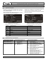 7
7
-
 8
8
-
 9
9
-
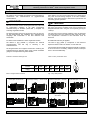 10
10
-
 11
11
-
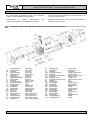 12
12
-
 13
13
-
 14
14
-
 15
15
-
 16
16
-
 17
17
-
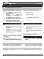 18
18
-
 19
19
-
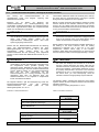 20
20
-
 21
21
-
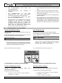 22
22
-
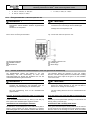 23
23
-
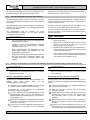 24
24
-
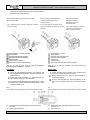 25
25
-
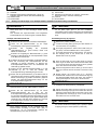 26
26
-
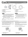 27
27
-
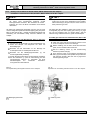 28
28
-
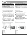 29
29
-
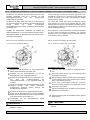 30
30
-
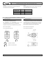 31
31
-
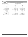 32
32
-
 33
33
-
 34
34
-
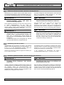 35
35
-
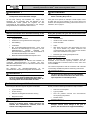 36
36
-
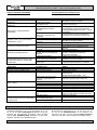 37
37
-
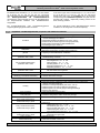 38
38
-
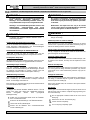 39
39
-
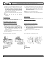 40
40
-
 41
41
-
 42
42
-
 43
43
-
 44
44
-
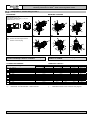 45
45
-
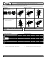 46
46
-
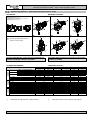 47
47
-
 48
48
-
 49
49
-
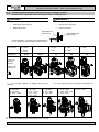 50
50
-
 51
51
-
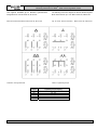 52
52
-
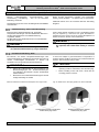 53
53
-
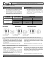 54
54
-
 55
55
-
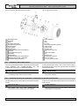 56
56
-
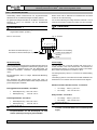 57
57
-
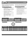 58
58
-
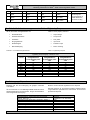 59
59
-
 60
60
-
 61
61
-
 62
62
-
 63
63
-
 64
64
-
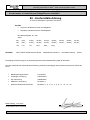 65
65
-
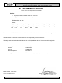 66
66
-
 67
67
-
 68
68


WEG MAS Getriebemotoren - Montageanleitung / Geared Motors - Mounting Benutzerhandbuch
- Kategorie
- Spielzeuge
- Typ
- Benutzerhandbuch
in anderen Sprachen
Verwandte Artikel
-
WEG Electric motors for explosive atmospheres Bedienungsanleitung
-
-
-
-
Andere Dokumente
-
ABB M2F series Instructions Manual
-
ASTRO AQUA Bedienungsanleitung
-
-
Ametek dunkermotoren GR Series Translation Of The Original Assembly Instruction
-
ABB DMP Series Operating And Maintenance Instructions Manual
-
Bauer FAN Separator Green Bedding Benutzerhandbuch
-
sauter V6R Assembly Instructions
-
Tamiya M-05Ra Bedienungsanleitung
-
MOTO GUZZI Daytona RS Workshop Manual
-
NORD Drivesystems Dust explosion protection Bedienungsanleitung