
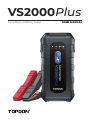
Jump Starter & Battery Tester USER MANUAL
VS2000Plus


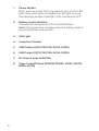
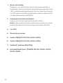
CONTENTS
Safety Is Always the First
Priority!
DE
21
22
22
23
26
26
29
32
33
EN
5
6
6
7
10
10
13
16
16
FR
35
36
36
37
40
40
43
46
46
IT
77
78
78
79
82
82
85
88
60
63
64
64
65
68
68
71
74
74
PT
49
50
50
52
54
54
57
60
88
ES
Section 1 About VS2000Plus
Section 2 What's in the
Box?
Section 7 Specications
Section 8 Warranty
Section 3 Product Overview
Section 4 Recharge the
Jump Starter
Section 5 How to Jump
Start a 12V Battery Vehicle?
Section 6 How to Perform a
Battery Test?

4
ENGLISH

5
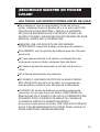
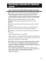
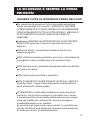
SAFETY IS ALWAYS THE FIRST
PRIORITY!
READ ALL INSTRUCTIONS BEFORE USE
For your safety, the safety of others, and to avoid any
damage to the product and your vehicle, CAREFULLY READ
AND MAKE SURE YOU FULLY UNDERSTAND ALL THE
SAFETY INSTRUCTIONS AND MESSAGES ON THIS MANUAL
BEFORE OPERATING.
ALWAYS WEAR APPROVED SAFETY GOGGLES while
working near a battery.
ONLY use the battery clamps that come with this product.
DO NOT use this product if the cable or the jump starter
has any damage.
DO NOT put the product under direct sunlight or in high
temperature areas.
DO NOT disassemble the product.
DO NOT SMOKE OR HAVE ANY FLAMES NEAR THE
VEHICLE when testing. The fuel and battery vapors are
highly ammable.
WARNING: Battery acid is extremely corrosive. If acid gets
into your eyes, FLUSH THEM THOROUGHLY WITH COLD
RUNNING WATER FOR AT LEAST 20 MINUTES AND SEEK
MEDICAL ATTENTION IMMEDIATELY.
If battery acid gets on your skin or clothing, WASH IT
IMMEDIATELY WITH A SOLUTION OF WATER AND BAKING
SODA.

6
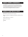
SECTION 1 ABOUT VS2000PLUS
The VS2000Plus is a two-in-one tool that combines
jump-starting and battery testing functions. It provides
a perfect solution for vehicle jump-starting, battery
testing, power supply, emergency illumination and
other scenarios.
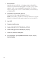
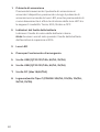
SECTION 2 WHAT'S IN THE BOX?
VS2000Plus Jump Starter
Smart Battery Clamps (Wireless Battery Tester)
USB Cable (Type-A to Type-C)
User Manual
Carrying Case

7
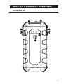
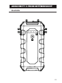
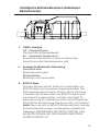
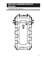
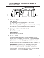
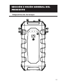
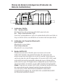
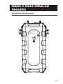
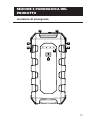
SECTION 3 PRODUCT OVERVIEW
Jump Starter
2
1
3
5 7
6 8
4

8
Power Button
Short press to power ON; long press to turn on the LED
light, then short press to toggle the LED light among
the following modes: Flashlight, SOS, Strobe and OFF.
Battery Level Indicators
Indicate the charge level of the internal battery.
Note: Only jump start vehicles when the battery level of
the jump starter is above 50%.
LED Light
Jump Start Socket
USB Output (QC3.0 12V/1.5A, 9V/2A, 5V/3A)
USB Output (QC3.0 12V/1.5A, 9V/2A, 5V/3A)
DC Output (Max 16.8V/10A)
Type-C Input/Output (PD60W 20V/3A, 15V/3A, 12V/3A,
9V/3A, 5V/3A)
1.
2.
3.
4.
5.
6.
7.
8.

9
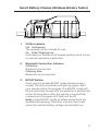
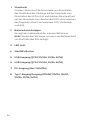
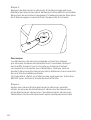
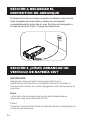
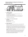
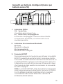
Smart Battery Clamps (Wireless Battery Tester)
1 2 3
OK/Err Indicator
OK:Solid green
The jumper starter is ready for use.
Err:Solid / ashing red
Illuminates or ashes red if reverse polarity, short circuit
or over temperature is detected.
Bluetooth Connection Indicator
Solid blue
Bluetooth connected
Flashing blue
Bluetooth not connected
BOOST Button
Short press to enable BOOST mode (forced output
mode). The status indicator will light up green. Start
your vehicle within 30 seconds. The BOOST mode will
be automatically turned off if no operation is performed
within 30 seconds or after the vehicle is successfully
cranked, and the green LED light will be off.
Note: Under BOOST mode, all safety protections are
disabled temporarily. Therefore, only use this mode
when the vehicle battery voltage is extremely low.
1.
2.
3.

10
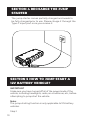
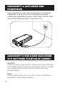
SECTION 4 RECHARGE THE JUMP
STARTER
The jump starter comes partially charged and needs to
be fully charged prior to use. Please charge it through the
Type-C input port once you receive it.
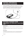
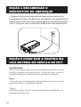
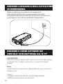
SECTION 5 HOW TO JUMP START A
12V BATTERY VEHICLE?
IMPORTANT
Make sure you have turned off all of the power loads of the
vehicle, including headlights, radio, air conditioner, etc., before
attempting to jump start the vehicle.
Note:
The jump-starting function is only applicable to 12V battery
vehicles.
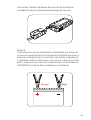
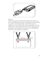
Step 1:

11
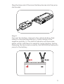
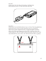
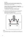
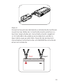
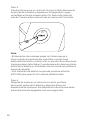
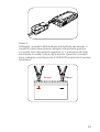
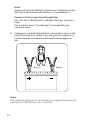
Step 2:
Connect the battery clamps to the vehicle battery. Red
clamp to the positive polarity (+), black clamp to the
negative polarity (-). The status indicator will illuminate
green, which indicates it is ready for jump starting. Just by
clamping the terminals correctly, the VS2000Plus delivers a
jump to the battery.
Plug the blue end of the smart battery clamps into the jump
start socket.

12
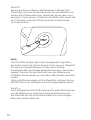
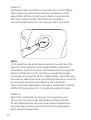
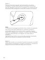
Note:
• The jump starter has a built-in buzzer that will ring when
reverse polarity, over temperature, short circuit, or other
improper connections are detected. Disconnect the clamps
from the battery if the buzzer rings and connect them again
after the issue is resolved.
• If the status indicator doesn't turn on, press the BOOST
Button to enable the forced output mode.
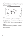
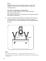
Step 3:
Try starting the vehicle. If it fails, disconnect the clamps from
the vehicle's battery and wait for 20 seconds, then reconnect
and try again. Do not attempt more than 3 consecutive jump
starts within 2 minutes.
Step 4:
After successfully jumpstarting the vehicle, remove the
clamps from vehicle battery and separate the clamps and
jump starter. Your jump starter will automatically power off
after a few seconds.

13
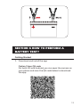
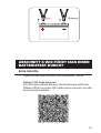
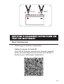
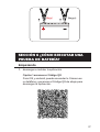
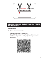
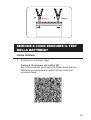
SECTION 6 HOW TO PERFORM A
BATTERY TEST?
Getting Started
Download and install the app
Option 1 Scan QR code
For both iOS and Android, you can open the camera on
your phone and scan the QR code below to download
the app.
1.

14
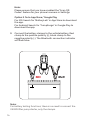
Note:
For battery testing functions, there is no need to connect the
VS2000Plus jump starter, only the clamps.
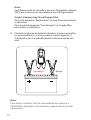
Note:
Please ensure that you have enabled the "Scan QR
Codes" feature for your phone's camera in Settings.
Option 2 Go to App Store / Google Play
For iOS: Search for "BatteryLab" in App Store to download
the app.
For Android: Search for "JumpSurge" in Google Play to
download the app.
Connect the battery clamps to the vehicle battery. Red
clamp to the positive polarity (+), black clamp to the
negative polarity (-). The Bluetooth connection indicator
will ash blue.
2.

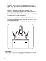
15
Connect the smart battery clamps (battery tester) to
your phone via Bluetooth
Open the BatteryLab/JumpSurge app and tap the
Bluetooth icon to establish connection with the unit.
3.
Perform Battery Tests
The BatteryLab/JumpSurge app provides detailed
instructions on how to test a battery. Thus, to perform a
battery / cranking / charging test, simply follow the on-screen
instructions.
Note:
The battery testing function is only applicable to 12V lead-acid
batteries.

16
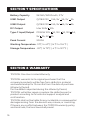
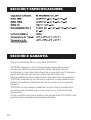
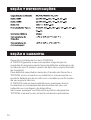
TOPDON One Year Limited Warranty
TOPDON warrants to its original purchaser that the
company's products will be free from defects in material
and workmanship for 12 months from the date of purchase
(Warranty Period).
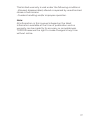
For the defects reported during the Warranty Period,
TOPDON will either repair or replace the defective part or
product according to its technical support analysis and
conrmation.
TOPDON shall not be liable for any incidental or consequential
damages arising from the device's use, misuse, or mounting.
If there is any conict between the TOPDON warranty policy
and local laws, the local laws shall prevail.
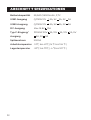
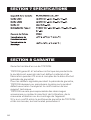
SECTION 7 SPECIFICATIONS
SECTION 8 WARRANTY
59.2Wh/16000mAh, 3.7V
QC18W 12V 1.5A, 9V 2A, 5V 3A
QC18W 12V 1.5A, 9V 2A, 5V 3A
Max 16.8V 10A
PD60W 20V 3A, 15V 3A, 12V 3A,
9V 3A, 5V 3A
2000A
-10℃ to 40℃ (14 ℉ to 104 ℉)
-20℃ to 75℃ (-4 ℉ to 167 ℉)
BatteryCapacity
USB1 Output
USB2 Output
DC Output
Type-C Input/Output
Peak Current
WorkingTemperature
StorageTemperature

17
Note:
All information in this manual is based on the latest
information available at the time of publication and no
warranty can be made for its accuracy or completeness.
TOPDON reserves the right to make changes at any time
without notice.
This limited warranty is void under the following conditions:
• Misused, disassembled, altered or repaired by unauthorized
stores or technicians.
• Careless handling and/or improper operation.

18
Any changes or modications not expressly approved by
the party responsible for compliance could void the user’s
authority to operate the equipment.
This device complies with Part 15 of the FCC Rules.
Operation is subject to the following two conditions:
(1) this device may not cause harmful interference, and
(2) this device must accept any interference received,
including interference that may cause undesired operation.
Note: This equipment has been tested and found to comply
with the limits for a Class B digital device, pursuant to Part
15 of the FCC Rules. These limits are designed to provide
reasonable protection against harmful interference in a
residential installation. This equipment generates, uses,
and can radiate radio frequency energy, and if not installed
and used in accordance with the instructions, may cause
harmful interference to radio communications. However,
there is no guarantee that interference will not occur in
a particular installation. If this equipment does cause
harmful interference to radio or television reception, which
can be determined by turning the equipment off and on,
the user is encouraged to try to correct the interference by
one or more of the following measures:
- Reorient or relocate the receiving antenna.
- Increase the separation between the equipment and
receiver.
- Connect the equipment into an outlet on a circuit
different from that to which the receiver is connected.
- Consult the dealer or an experienced radio/TV technician
for help.
SECTION 9 FCC

19

20
DEUTSCH
Seite laden ...
Seite laden ...
Seite laden ...
Seite laden ...
Seite laden ...
Seite laden ...
Seite laden ...
Seite laden ...
Seite laden ...
Seite laden ...
Seite laden ...
Seite laden ...
Seite laden ...
Seite laden ...
Seite laden ...
Seite laden ...
Seite laden ...
Seite laden ...
Seite laden ...
Seite laden ...
Seite laden ...
Seite laden ...
Seite laden ...
Seite laden ...
Seite laden ...
Seite laden ...
Seite laden ...
Seite laden ...
Seite laden ...
Seite laden ...
Seite laden ...
Seite laden ...
Seite laden ...
Seite laden ...
Seite laden ...
Seite laden ...
Seite laden ...
Seite laden ...
Seite laden ...
Seite laden ...
Seite laden ...
Seite laden ...
Seite laden ...
Seite laden ...
Seite laden ...
Seite laden ...
Seite laden ...
Seite laden ...
Seite laden ...
Seite laden ...
Seite laden ...
Seite laden ...
Seite laden ...
Seite laden ...
Seite laden ...
Seite laden ...
Seite laden ...
Seite laden ...
Seite laden ...
Seite laden ...
Seite laden ...
Seite laden ...
Seite laden ...
Seite laden ...
Seite laden ...
Seite laden ...
Seite laden ...
Seite laden ...
Seite laden ...
Seite laden ...
-
 1
1
-
 2
2
-
 3
3
-
 4
4
-
 5
5
-
 6
6
-
 7
7
-
 8
8
-
 9
9
-
 10
10
-
 11
11
-
 12
12
-
 13
13
-
 14
14
-
 15
15
-
 16
16
-
 17
17
-
 18
18
-
 19
19
-
 20
20
-
 21
21
-
 22
22
-
 23
23
-
 24
24
-
 25
25
-
 26
26
-
 27
27
-
 28
28
-
 29
29
-
 30
30
-
 31
31
-
 32
32
-
 33
33
-
 34
34
-
 35
35
-
 36
36
-
 37
37
-
 38
38
-
 39
39
-
 40
40
-
 41
41
-
 42
42
-
 43
43
-
 44
44
-
 45
45
-
 46
46
-
 47
47
-
 48
48
-
 49
49
-
 50
50
-
 51
51
-
 52
52
-
 53
53
-
 54
54
-
 55
55
-
 56
56
-
 57
57
-
 58
58
-
 59
59
-
 60
60
-
 61
61
-
 62
62
-
 63
63
-
 64
64
-
 65
65
-
 66
66
-
 67
67
-
 68
68
-
 69
69
-
 70
70
-
 71
71
-
 72
72
-
 73
73
-
 74
74
-
 75
75
-
 76
76
-
 77
77
-
 78
78
-
 79
79
-
 80
80
-
 81
81
-
 82
82
-
 83
83
-
 84
84
-
 85
85
-
 86
86
-
 87
87
-
 88
88
-
 89
89
-
 90
90


in anderen Sprachen
- français: Topdon VS2000Plus Manuel utilisateur
- español: Topdon VS2000Plus Manual de usuario
- italiano: Topdon VS2000Plus Manuale utente
- português: Topdon VS2000Plus Manual do usuário
Verwandte Papiere
-
 Topdon VS2000 Benutzerhandbuch
-
Topdon JumpSurge3000 Benutzerhandbuch
-
 Topdon JUMPSURGE1200 Benutzerhandbuch
-
Topdon BT20 Benutzerhandbuch
-
 Topdon V1500 Benutzerhandbuch
-
Topdon TB6000Pro Benutzerhandbuch
-
-
Topdon VOLCANO 2000Pros Benutzerhandbuch
-
Topdon BT50 Benutzerhandbuch
-
Topdon BT Mobile Pros Benutzerhandbuch


