Aeg-Electrolux DD6660-M Benutzerhandbuch
- Kategorie
- Dunstabzugshauben
- Typ
- Benutzerhandbuch

DD6660-M
DD6690-M
User Manual Cooker Hood

2
EN
INDEX
RECOMMENDATIONS AND SUGGESTIONS .....................................................................................................................3
CHARACTERISTICS ............................................................................................................................................................4
INSTALLATION.....................................................................................................................................................................6
USE ......................................................................................................................................................................................9
MAINTENANCE .................................................................................................................................................................10

3
EN
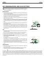
RECOMMENDATIONS AND SUGGESTIONS
The Instructions for Use apply to several versions of this appliance. Accord-
ingly, you may fi nd descriptions of individual features that do not apply to
your specifi c appliance.
INSTALLATION
• The manufacturer will not be held liable for any damages resulting from in-
correct or improper installation.
• The minimum safety distance between the cooker top and the extractor hood
is 650 mm (some models can be installed at a lower height, please re-fer to the
paragraphs on working dimensions and installation).
• Check that the mains voltage corresponds to that indicated on the rating plate
fi xed to the inside of the hood.
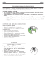
• For Class I appliances, check that the domestic power supply guarantees
adequate earthing. Connect the extractor to the exhaust fl ue through a pipe
of minimum diameter 120 mm. The route of the fl ue must be as short as pos-
sible.
• Do not connect the extractor hood to exhaust ducts carrying combustion fumes
(boilers, fi replaces, etc.).
• If the extractor is used in conjunction with non electrical appliances (e.g. gas
burning appliances), a suffi cient degree of aeration must be guaranteed in the
room in order to prevent the backfl ow of exhaust gas. The kitchen must have
an opening communicating directly with the open air in order to guarantee the
entry of clean air.
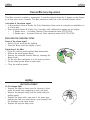
USE
• The extractor hood has been designed exclusively for domestic use to elimi-
nate kitchen smells.
• Never use the hood for purposes other than for which it has been designed.
• Never leave high naked fl ames under the hood when it is in operation.
• Adjust the fl ame intensity to direct it onto the bottom of the pan only, making
sure that it does not engulf the sides.
• Deep fat fryers must be continuously monitored during use: overheated oil can
burst into fl ames.
• Do not fl ambè under the range hood; risk of fi re
• This appliance is not intended for use by persons (including children) with
reduced physical, sensory or mental capabilities, or lack of experience and
knowledge, unless they have been given supervision or instruction concerning
use of the appliance by a person responsible for their safety.
• Children should be supervised to ensure that they do not play with the appli-
ance.
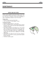
MAINTENANCE
• Switch off or unplug the appliance from the mains supply before carrying out
any maintenance work.
• Clean and/or replace the Filters after the specifi ed time period (Fire hazard).
• Clean the hood using a damp cloth and a neutral liquid detergent.
The symbol
on the product or on its packaging indicates that this product may not be treated as household waste. Instead
it shall be handed over to the applicable collection point for the recycling of electrical and electronic equipment. By ensuring this
product is disposed of correctly, you will help prevent potential negative consequences for the environment and human health,
which could otherwise be caused by inappropriate waste handling of this product. For more detailed information about recycling
of this product, please contact your local city offi ce, your household waste disposal service or the shop where you purchased
the product.

4
EN
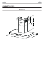
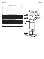
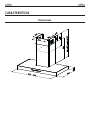
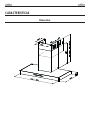
CHARACTERISTICS
Dimensions

5
EN
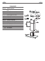
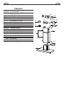
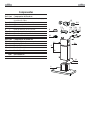
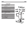
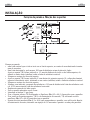
Components
Ref. Q.ty Product Components
1 1 Hood Body, complete with: Controls, Light, Blower,
Filters
2 1 Telescopic Chimney comprising:
2.1 1 Upper Section
2.2 1 Lower Section
9 1 Reducer Flange ø 150-120 mm
10 1 Damper ø 150
14.1 2 Air Outlet Connection Extension
15 1 Air Outlet Connection
Ref. Q.ty Installation Components
7.2.1 2 Upper Chimney Section Fixing Brackets
7.3 1 Air Outlet Connection Support
11 6 Wall Plugs
12a 6 Screws 4,2 x 44,4
12c 6 Screws 2,9 x 9,5
Q.ty Documentation
1 Instruction Manual
2.1
2.2
2
12c
12a
7.2.1 11
11
12a
1
7.3
9
14.1
15
10

6
EN
INSTALLATION
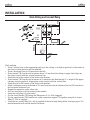
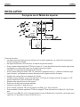
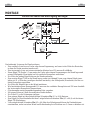
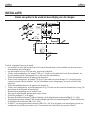
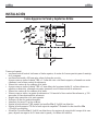
Wall drilling and bracket fi xing
Wall marking:
• Draw a vertical line on the supporting wall up to the ceiling, or as high as practical, at the centre of
the area in which the hood will be installed.
• Draw a horizontal line at 650 mm above the hob.
• Place bracket 7.2.1 on the wall as shown about 1-2 mm from the ceiling or upper limit align-ing
the centre (notch) with the vertical reference line.
• Mark the wall at the centres of the holes in the bracket.
• Place bracket 7.2.1 on the wall as shown at X mm below the fi rst bracket (X = height of the upper
chimney section supplied), aligning the centre (notch) with the vertical line.
• Mark the wall at the centres of the holes in the bracket.
• Mark a reference point as indicated at 116 mm from the vertical reference line and 330 mm above
the horizontal reference line.
• Repeat this operation on the other side.
• Drill ø 8 mm holes at all the centre points marked.
• Insert the wall plugs 11 in the holes.
• Fix the lower bracket 7.2.1 using the 12a screws (4,2 x 44,4) supplied.
• Fix the upper bracket 7.2.1 and the air outlet connection support 7.3 together using the 2 screws
12a (4,2 x 44,4) supplied.
• Insert the two screws 12a (4,2 x 44,4) supplied in the hood body fi xing holes, leaving a gap of 5-6
mm between the wall and the head of the screw.
11
12a
330
X
116
1÷2
116
650 min.
7.2.1
7.3

7
EN
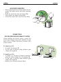
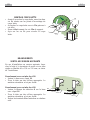
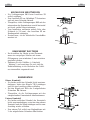
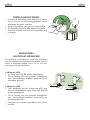
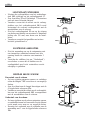
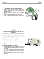
HOOD BODY MOUNTING
• Before attaching the hood body, tighten the two
screws Vr located on the hood body mounting
points.
• Hook the hood body onto the screws 12a.
• Fully tighten the support screws 12a.
• Adjust the screws Vr to level the hood body.
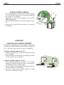
CONNECTIONS
DUCTED VERSION AIR EXHAUST SYSTEM
When installing the ducted version, connect the
hood to the chimney using either a fl exible or rigid
pipe ø 150 or 120mm, the choice of which is left
to the installer.
To install a ø 150
• To install the dumper 10
• Fix the pipe in position using suffi cient pipe
clamps (not supplied).
To install a ø 120
• To install a ø 120 mm air exhaust connection,
insert the reducer fl ange 9 on the dumper 10.
• Fix the pipe in position using suffi cient pipe
clamps (not supplied)
.• Remove any activated charcoal fi lters.
ø 120
ø 150
10
10
9
12a
Vr

8
EN
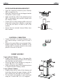
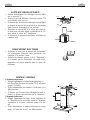
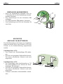
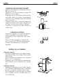
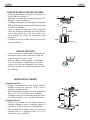
RECIRCULATION VERSION AIREOUTLET
• Insert the connection extension pieces laterally
14.1 in connection 15.
• Insert the Connector 15 into the Support bracket
7.3 and fi x it with a screw.
• Make sure that the outlet of the extension pieces
14.1 is horizontally and vertically aligned with
the chimney outlets.
• Connect the air outlet connection 15 to the hood
body outlet using either a fl exible or rigid pipe
ø 150 mm, the choice of which is left to the
installer.
• Ensure that the activated charcoal fi lters have
been inserted.
ELECTRICAL CONNECTION
• Connect the hood to the mains through a two-
pole switch having a contact gap of at least 3
mm.
• Remove the grease fi lters (see paragraph Main-
tenance) being sure that the connector of the
feeding cable is correctly inserted in the socket
placed on the side of the fan.
CHIMNEY ASSEMBL
Y
Upper exhaust Chimney
• Slightly widen the two sides of the upper fl ue
and hook them behind the brackets 7.2.1, making
sure that they are well seated.
• Secure the sides to the brackets by using the 4
screws 12c (2,9 x 9,5) supplied.
• Make sure that the outlet of the extensions pieces
is aligned with the chimney outlets.
Lower exhaust Chimney
• Slightly widen the two sides of the chimney and
hook them between the upper chimney and the
wall, making sure that they are well seated.
• Fix the lower part laterally to the hood body
using the 2 screws 12c (2,9 x 9,5) supplied.
12c
2.1
2.2
2
7.2.1
12c
ø 150
15
14.1
7.3

9
EN
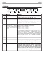
USE
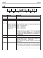
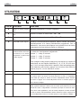
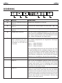
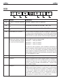
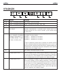
BUTTON DISPLAY FUNCTIONS
A
Displays the set speed Turns the suction motor on and off
B
Displays the set speed Decreases the speed of the motor V3→ V2→ V1
C
Displays the set speed Increases the speed of the motor V1→ V2→ V3
D
Displays HI The spot fl ash-
es
Starts maximum suction speed. After 5 minutes the speed will return automatically
to the one set before. This function can be deactivated by pressing the button
again (the decimal point at the centre of the display will fl ash).
E
Displays the time remaining
before the hood turns off
(countdown) and the Set
speed. The spot at the bot-
tom right fl ashes
Enables automatic delayed shutdown of the appliance (Delay), with a delay that
depends on the working speed set.
Speed 1 → delay 20 minutes
Speed 2 → delay 15 minutes
Speed 3 → delay 10 minutes
The proposed delay time can be changed by pressing the button successively
and selecting one of the options available (5, 10, 15, 20, 25 and 30 minutes).
At the end of the time selected the appliance will turn off automatically. To
deactivate this function, simply press the button until the option selected is 0
or turn the motor off.
F
Turns the hob lighting system on and off
Displays F Indicates the need to wash the metal grease fi lters. The alarm is triggered after
the Hood has been in operation for 100 working hours. This indication is only
visible when the motor is turned off. To reset the alarm:
Turn the motor off and press button D for approximately 3 seconds, until the
display turns off.
Displays C Indicates the need to change the activated charcoal fi lters, and also to wash the
metal grease fi lters. The alarm is triggered after the Hood has been in operation
for 200 working hours. This indication is only visible when the motor is turned
off. This indication must be activated following the procedure described in the
section on maintenance of the activated charcoal fi lter. To reset the alarm:
Turn the motor off and press button D for approximately 3 seconds, until the
display turns off.
A B C D E F

10
EN
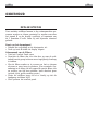
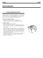
MAINTENANCE
METAL GREASE FILTERS
Filters can be washed in the dish machine. They need
to be washed when F-sign appears on the display or in
any case every 2 months, or even more frequently in
case of particularly intensive use of the hood.
Alarm reset
• Switch off the hood and the lights.
• Press the D-key till the display is unlit.
Cleaning the fi lters
• Pull the comfort panels to open them.
• Remove the fi lters one by one pushing them towards
the back side of the hood unit and simultaneously
pulling downwards.
• Any kind of bending of the fi lters has to be avoided
when washing them. Before fi tting them again into
the hood make sure that they are completely dry.
(The colour of the fi lter surface may change through-
out the time but this has no infl uence to the fi lter
effi ciency).
• When fi tting the fi lters into the hood pay attention
that they are mounted in correct position the handle
facing outwards.
• Close the comfort panel.

11
EN
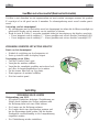
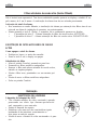
Charcoal fi lter (recycling version)
This fi lter cannot be washed or regenerated. It must be replaced when the C appears on the display
or at least once every 4 months. The fi lter saturation alarm has to be activated already before.
Activation of the alarm signal
• In Recirculation Version Hoods, the Filter Saturation Alarm must be activated on installation or
at a later date.
• Press and hold button E (Delay) for 5 seconds, until confi rmation appears on the display:
• C fl ashes twice – Activated Charcoal Filter saturation alarm ACTIVATED.
• C fl ashes once – Activated Charcoal Filter saturation alarm DEACTIVATED.
REPLACING THE CHARCOAL FILTER
Reset of the alarm signal
• Switch off the hood and the lighting.
• Press the D-key until the display is unlit.
Replacing of the fi lter
• Open the comfort panels pulling them downwards.
• Remove the metal grease fi lters.
• Remove the saturated charcoal fi lter by releasing the
fi xing hooks
• Fit the new fi lter and fasten it in its correct position.
• Put the metal grease fi lters in their seats.
• Close the comfort panels.
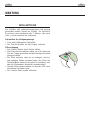
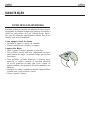
Lighting
LIGHT REPLACEMENT
20 W halogen light.
• Remove the snap-on lamp cover by levering it from
under the metal ring, supporting it with one hand.
• Remove the halogen lamp from the lamp holder by
pulling gently.
• Replace the lamp with a new one of the same type,
making sure that you insert the two pins properly into
the housings on the lamp holder.
• Replace the snap-on lamp cover.

12
FR
SOMMAIRE
RECOMMENDATIONS AND SUGGESTIONS ...................................................................................................................13
CHARACTERISTICS ..........................................................................................................................................................14
INSTALLATION...................................................................................................................................................................16
USE ....................................................................................................................................................................................19
MAINTENANCE .................................................................................................................................................................20

13
FR
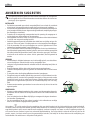
CONSEILS ET SUGGESTIONS
La présente notice d’emploi vaut pour plusieurs versions de l’appareil. Elle peut
contenir des descriptions d’accessoires ne fi gurant pas dans votre appareil.
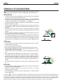
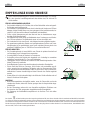
INSTALLATION
• Le fabricant décline toute responsabilité en cas de dommage dû à une installation
non correcte ou non conforme aux règles de l’art.
• La distance minimale de sécurité entre le plan de cuisson et la hotte doit être de
650 mm au moins (certains modèles peuvent être installés à une hauteur inférieure
: se reporter aux paragraphes « Encombrement » et « Installation »).
• Vérifi er que la tension du secteur correspond à la valeur qui fi gure sur la plaquette
apposée à l’intérieur de la hotte.
• Pour les Appareils appartenant à la Ière Classe, veiller à ce que la mise à la terre
de l’installation électrique domestique ait été effectuée conformément aux normes
en vigueur.
• Connecter la hotte à la sortie d’air aspiré à l’aide d’une tuyauterie d’un diamètre
égal ou supérieur à 120 mm. Le parcours de la tuyauterie doit être le plus court
possible.
• Eviter de connecter la hotte à des conduites d’évacuation de fumées issues d’une
combustion tel que (Chaudière, cheminée, etc…).
• Si vous utilisez des appareils qui ne fonctionnent pas à l’électricité dans la pièce ou
est installée la hotte (par exemple: des appareils fonctionnant au gaz), vous devez
prévoir une aération suffi sante du milieu. Si la cuisine en est dépourvue, pratiquez
une ouverture qui communique avec l’extérieur pour garantir l’infi ltration de l’air
pur.
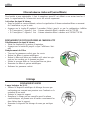
UTILISATION
• La hotte a été conçue exclusivement pour l’usage domestique, dans le but d’éli-
miner les odeurs de la cuisine.
• Ne jamais utiliser abusivement la hotte.
• Ne pas laisser les fl ammes libres à forte intensité quand la hotte est en service.
• Toujours régler les fl ammes de manière à éviter toute sortie latérale de ces der-
nières par rapport au fond des marmites.
• Contrôler les friteuses lors de l’utilisation car l’huile surchauffée pourrait s’enfl am-
mer.
• Ne pas préparer d’aliments fl ambés sous la hotte de cuisine : risque d’incendie
• Cet appareil ne doit pas être utilisé par des personnes (y compris les enfants)
ayant des capacités psychiques, sensorielles ou mentales réduites, ni par des
personnes n’ayant pas l’expérience et la connaissance de ce type d’appareils, à
moins d’être sous le contrôle et la formation de personnes responsables de leur
sécurité.
• Les enfants doivent être surveillés pour s’assurer qu’ils ne jouent pas avec l’appa-
reil.
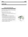
ENTRETIEN
• Avant de procéder à toute opération d’entretien, retirer la hotte en retirant la fi che
ou en actionnant l’interrupteur général.
• Effectuer un entretien scrupuleux et en temps dû des Filtres, à la cadence
conseillée (Risque d’incendie).
• Pour le nettoyage des surfaces de la hotte, il suffi t d’utiliser un chiffon humide et
détersif liquide neutre.
Le symbole sur le produit ou son emballage indique que ce produit ne peut être traité comme déchet ménager. Il doit plutôt être remis au
point de ramassage concerné, se chargeant du recyclage du matériel électrique et électronique. En vous assurant que ce produit est éliminé
correctement, vous favorisez la prévention des conséquences négatives pour l’environnement et la santé humaine qui, sinon, seraient le résultat
d’un traitement inapproprié des déchets de ce produit. Pour obtenir plus de détails sur le recyclage de ce produit, veuillez prendre contact avec le
bureau municipal de votre région, votre service d’élimination des déchets ménagers ou le magasin où vous avez acheté le produit.

14
FR
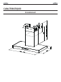
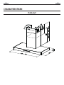
CARACTERISTIQUES
Encombrement

15
FR
Composants
Réf. Q.té Composants du produit
1 1 Corps Hotte équipé de: Comandes, Lumière,Groupe
Ventilateur,Filtres
2 1 Cheminée Télescopique formée de :
2.1 1 Cheminée Supérieure
2.2 1 Cheminée Inférieure
9 1 Flasque de Réduction ø 150-120 mm
10 1 Buse avec clapet
14.1 2 Rallonge Raccord Sortie Air
15 1 Raccord Sortie Air
Réf. Q.té Composants de l’installation
7.2.1 2 Brides Fixation Cheminée Supérieure
7.3 1 Bride Support Raccord
11 6 Chevilles
12a 6 Vis 4,2 x 44,4
12c 6 Vis 2,9 x 9,5
Q.té Documentation
1 Notice d’emploi
2.1
2.2
2
12c
12a
7.2.1 11
11
12a
1
7.3
9
14.1
15
10

16
FR
INSTALLATION
Perçage du mur et fi xation des équerres
Tracer sur la paroi:
• une ligne verticale allant jusqu’au plafond ou à la limite supérieure, au centre de la zone prévue
pour le montage de la hotte;
• une ligne horizontale à 650 mm min. au-dessus du plan de cuisson.
• Poser comme indiqué une bride 7.2.1 sur la paroi à 1-2 mm du plafond ou de la limite supé-rieure,
en alignant son centre (découpes) sur la ligne verticale de repère.
• Marquer les centres des trous rainurés de la bride.
• Poser comme indiqué la bride 7.2.1 à X mm sous la première bride (X = hauteur cheminée supé-
rieure fournie), en alignant son centre (découpes) sur la ligne verticale de repère.
• Marquer les centres des trous rainurés de la bride.
• Marquer comme indiqué, un point de référence à 116 mm de la ligne verticale de repère, et 330
mm au-dessus de la ligne horizontale de repère.
• Répéter cette opération sur le côté opposé.
• Percer de ø 8 mm tous les points marqués.
• Insérer les chevilles 11 dans les trous.
• Fixer la bride inférieure 7.2.1 en utilisant les vis 12a (4,2 x 44,4) fournies.
• Fixer ensemble la bride supérieure 7.2.1 et le support 7.3 en utilisant les vis 12a (4,2 x 44,4) four-
nies.
• Visser les 2 vis 12a (4,2 x 44,4) fournies dans les trous de fi xation du corps hotte, en laissant un le
espace de 5-6 mm entre le mur et la tête de la vis
11
12a
330
X
116
1÷2
116
650 min.
7.2.1
7.3

17
FR
MONTAGE CORPS HOTTE
• Avant d’accrocher le corps hotte, serrer les deux
vis Vr situées sur les points d’accrochage du
corps hotte.
• Accrocher le corps hotte aux vis 12a prévues à
cet effet.
• Serrer défi nitivement les vis 12a de support.
• Agir sur les vis Vr pour niveler le corps
hotte.
BRANCHEMENTS
SORTIE AIR VERSION ASPIRANTE
En cas d’installation en version aspirante, bran-
cher la hotte à la tuyauterie de sortie via un tube
rigide ou fl exible de ø 150 ou 120 mm, au choix
de l’installateur.
Branchement avec un tube de ø150
• Insérer la buse avec clapet 10.
• Fixer le tube par des colliers appropriés. Le
matériau nécessaire n’est pas fourni.
Branchement avec un tube de ø120
• Insérer le fl asque de réduction 9 sur la buse
avec clapet 10.
• Fixer le tube par des colliers appropriés. Le
matériau nécessaire n’est pas fourni.
• Retirer les éventuels fi ltres antiodeur au charbon
actif.
ø 120
ø 150
10
10
9
12a
Vr

18
FR
SORTIE AIR VERSION FILTRANTE
• Insérer latéralement les rallonges raccord 14.1
sur le raccord 15.
• Placer le raccord 15 dans l’étrier de soutien 7.3
en le fi xant avec une vis.
• S’assurer que la sortie des rallonges raccord 14.1
se trouve au niveau des bouches de la cheminée
aussi bien en horizontal qu’en vertical.
• Brancher le raccord 15 à la sortie du corps de
la hotte avec un tube rigide ou fl exible de ø 150
mm, selon le choix de l’installateur.
• S’assurer de la présence des fi ltres antiodeur au
charbon actif.
BRANCHEMENT ÉLECTRIQUE
• Brancher la hotte sur le secteur en interposant
un interrupteur bipolaire avec ouverture des
contacts d’au moins 3 mm.
• Enlever les fi ltres à graisse (voir § “Entretien”)
et s’assurer que le connecteur du câble d’ali-
mentation soit bien branché dans la prise du
diffuseur.
MONTAGE CHEMINÉE
Cheminée supérieure
• Elargir légèrement les deux bords latériaux, et
les accrocher derrières les brides 7.2.1; refermer
jusqu’à la butée.
• Fixer latéralement aux brides à l’aide des 4 vis
12c fournies.
• S’assurer que la sortie des rallonges raccord se
trouve au niveau des bouches de la cheminée.
Cheminée inférieure
• Elargir légèrement les deux bords latériaux de
la Cheminée et les accrocher entre la Cheminée
supérieure et la paroi; refermer jusqu’à la bu-
tée.
• Fixer latéralement la partie inférieure au corps
hotte, à l’aide des deux 2 vis 12c fournies.
12c
2.1
2.2
2
7.2.1
12c
ø 150
15
14.1
7.3

19
FR
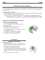
UTILISATION
TOUCHE AFFICHEUR FONCTIONS
A
Affi che la vitesse program-
mée.
Branche et débranche le moteur d’aspiration
B
Affi che la vitesse program-
mée.
Diminue la vitesse du moteur V3 → V2 → V1
C
Affi che la vitesse program-
mée.
Augmente la vitesse du moteur V1 → V2 → V3
D
Affi che HI Le point clignote
Démarre la vitesse maximum d’aspiration. Après 5 minutes, elle retourne
automatiquement à la vitesse précédemment programmée. Pour la
débrancher, vous pouvez aussi appuyer une nouvelle fois sur la touche
(clignotement du point décimal central de l’affi cheur).
E
Affi che le temps restant avant
le débranchement de la hotte
(countdown) et la vitesse
programmée. Le point en bas
à droite clignote.
Active le débranchement automatique différé (Delay) de l’appareil, selon
la vitesse de fonctionnement programmée :
Vitesse 1 → delay 20 minutes
Vitesse 2 → delay 15 minutes
Vitesse 3 → delay 10 minutes
Pour changer le delay proposé, appuyer en succession sur la touche et
sélectionner une des options disponibles (5, 10, 15, 20, 25 et 30 minu-
tes). À la fi n du temps sélectionné, l’appareil s’éteint automatiquement.
Pour désactiver cette fonction, appuyer sur la touche et faire défi ler les
options jusqu’à 0, ou bien éteindre le moteur.
F Branche et débranche l’éclairage du plan de cuisson
Affi che F Signale la nécessité de laver les fi ltres à graisse métalliques. L’alarme entre
en fonction après 100 heures de travail effectif de la hotte. La signalisation
n’est visible que lorsque le moteur est éteint. Réinitialisation alarme :Éteindre
le moteur et appuyer sur la touche D pendant environ 3 secondes jusqu’à ce
que l’affi cheur s’éteigne.
Affi che C Signale la nécessité de remplacer les fi ltres à charbon actif, ainsi que de laver les
fi ltres à graisse métalliques. L’alarme entre en fonction après 200 heures de travail
effectif de la hotte. La signalisation n’est visible que lorsque le moteur est éteint.
Pour activer cette signalisation, suivre la marche indiquée à la section entretien
du fi ltre à charbon actif.Réinitialisation alarme :Éteindre le moteur et appuyer sur
la touche D pendant environ 3 secondes jusqu’à ce que l’affi cheur s’éteigne.
A B C D E F

20
FR
ENTRETIEN
FILTRES À GRAISSE MÉTALLIQUES
Ils sont lavables même en lave-vaisselle et doivent être
lavés chaque fois que le symbole F s’affi che ou environ
tous les 2 mois ou plus souvent même, en cas d’utilisation
particulièrement intensive.
Rétablissement du signal d’alarme
• Eteint les lumières et le moteur d’aspiration.
• Appuyer sur la touche D jusqu’à ce que l’affi cheur
s’éteigne.
Nettoyage des fi ltres
• Tirer sur les panneaux confort pour les ouvrir.
• Retirer les fi ltres, un à un, en les poussant vers la partie
postérieure du groupe tout en tirant vers le bas.
• Laver les fi ltres en évitant de les plier, et les faire sécher
avant de les remonter. (Tout changement de couleur sur
la surface du fi ltre, susceptible de se produire avec le
temps, ne nuit en rien à l’effi cacité de ce dernier.)
• Remonter les fi ltres en faisant attention de tenir la
poignée vers la partie externe visible.
• Refermer les panneaux confort.
Seite wird geladen ...
Seite wird geladen ...
Seite wird geladen ...
Seite wird geladen ...
Seite wird geladen ...
Seite wird geladen ...
Seite wird geladen ...
Seite wird geladen ...
Seite wird geladen ...
Seite wird geladen ...
Seite wird geladen ...
Seite wird geladen ...
Seite wird geladen ...
Seite wird geladen ...
Seite wird geladen ...
Seite wird geladen ...
Seite wird geladen ...
Seite wird geladen ...
Seite wird geladen ...
Seite wird geladen ...
Seite wird geladen ...
Seite wird geladen ...
Seite wird geladen ...
Seite wird geladen ...
Seite wird geladen ...
Seite wird geladen ...
Seite wird geladen ...
Seite wird geladen ...
Seite wird geladen ...
Seite wird geladen ...
Seite wird geladen ...
Seite wird geladen ...
Seite wird geladen ...
Seite wird geladen ...
Seite wird geladen ...
Seite wird geladen ...
Seite wird geladen ...
Seite wird geladen ...
Seite wird geladen ...
Seite wird geladen ...
Seite wird geladen ...
Seite wird geladen ...
Seite wird geladen ...
Seite wird geladen ...
-
 1
1
-
 2
2
-
 3
3
-
 4
4
-
 5
5
-
 6
6
-
 7
7
-
 8
8
-
 9
9
-
 10
10
-
 11
11
-
 12
12
-
 13
13
-
 14
14
-
 15
15
-
 16
16
-
 17
17
-
 18
18
-
 19
19
-
 20
20
-
 21
21
-
 22
22
-
 23
23
-
 24
24
-
 25
25
-
 26
26
-
 27
27
-
 28
28
-
 29
29
-
 30
30
-
 31
31
-
 32
32
-
 33
33
-
 34
34
-
 35
35
-
 36
36
-
 37
37
-
 38
38
-
 39
39
-
 40
40
-
 41
41
-
 42
42
-
 43
43
-
 44
44
-
 45
45
-
 46
46
-
 47
47
-
 48
48
-
 49
49
-
 50
50
-
 51
51
-
 52
52
-
 53
53
-
 54
54
-
 55
55
-
 56
56
-
 57
57
-
 58
58
-
 59
59
-
 60
60
-
 61
61
-
 62
62
-
 63
63
-
 64
64


Aeg-Electrolux DD6660-M Benutzerhandbuch
- Kategorie
- Dunstabzugshauben
- Typ
- Benutzerhandbuch
in anderen Sprachen
- English: Aeg-Electrolux DD6660-M User manual
- français: Aeg-Electrolux DD6660-M Manuel utilisateur
- español: Aeg-Electrolux DD6660-M Manual de usuario
- italiano: Aeg-Electrolux DD6660-M Manuale utente
- Nederlands: Aeg-Electrolux DD6660-M Handleiding
- português: Aeg-Electrolux DD6660-M Manual do usuário
Verwandte Artikel
Andere Dokumente
-
AEG DD8694-M Benutzerhandbuch
-
-
-
Electrolux EFC9140X Benutzerhandbuch
-
ROBLIN Univers Bedienungsanleitung
-
-
-
Falcon RMG1HD90SG/-EU Benutzerhandbuch
-
Electrolux WHGL9040CN Benutzerhandbuch
-