
Installation instructions
Montageanweisung
StativgerätStativgerät
StativgerätStativgerät
Stativgerät
TT
TT
Tripod-mounted deviceripod-mounted device
ripod-mounted deviceripod-mounted device
ripod-mounted device

Seite / Page 2
38628, Edition / Ausgabe 2012-05, Version 5
DeutschEnglish
InhaltsverzeichnisInhaltsverzeichnis
InhaltsverzeichnisInhaltsverzeichnis
Inhaltsverzeichnis SeiteSeite
SeiteSeite
Seite
1 Rollen montieren ................................................ 7
2 Farbfolie (Sonderzubehör) aufkleben ................ 7
3 Stativrohr montieren........................................... 8
4 Kunststoff-Halbringe einsetzen .......................... 8
5 Federarm montieren .......................................... 9
6 Endgerät montieren ........................................ 11
7 Federkraft einstellen ........................................ 12
8 Austausch der Sicherungen ............................. 14
9 Technische Daten ............................................ 16
Packliste Stativfuß
- 1 Stativfuß
Zur Montage geliefertes Zubehör:
- 2 Antistatische Rollen mit Bremsen
- 2 Rollen ohne Bremsen
Packliste Stativrohr und Federarm
- 1 Stativrohr
- 1 Federarm
Zur Montage benötigtes Zubehör:
- 1 Farbfolie (Sonderzubehör)
- 2 Kunststoff-Halbringe und 2 Schrauben (nicht bei der
Variante mit Gehäuse, Pos. 1, Seite 14)
- 1 Kunststoffhülse
- 1 Sicherungssegment
- 1 Scheibe
- 1 Sicherungsring
- 1 Sicherungsring-Zange
TT
TT
Table of contentsable of contents
able of contentsable of contents
able of contents PP
PP
Pageage
ageage
age
1 Mounting the rollers ........................................... 7
2 Sticking on the color foil (special accessories)... 7
3 Mounting the tripod tubes .................................. 8
4 Inserting the plastic semi-circular rings .............. 8
5 Installing the spring arm ..................................... 9
6 Mounting the end device.................................. 11
7 Setting the spring force ....................................12
8 Change the fuses............................................. 14
9 Technical data .................................................. 16
Packing list, Tripod base
- 1 Tripod base
Accessories supplied for assembly:
- 2 anti-static rollers with brakes
- 2 rollers without brakes
Packing list, Tripod tube and spring arm
- 1 tripod tube
- 1 spring arm
Accessories required for assembly:
- 1 color foil (special accessories)
- 2 plastic half rings and 2 screws (not for version with
cover, pos. 1 on page 14)
- 1 plastic sleeve
- 1 securing segment
- 1 disk
- 1 securing ring
- 1 retaining ring - pliers
Ondal Medical Systems GmbH
Wellastraße 6 • 36088 Hünfeld • Deutschland
Telefon: +49 / (0)6652 / 81-600
Fax: +49 / (0)6652 / 81-392
© Ondal Medical Systems GmbH, 2012
38628, Ausgabe 2012-05, Version 5
Ondal Medical Systems GmbH
Wellastraße 6 • D-36088 Hünfeld • Germany
Phone: +49 / (0)6652 / 81-600
Fax: +49 / (0)6652 / 81-392
© Ondal Medical Systems GmbH, 2012
38628, Edition 2012-05, Version 5

Seite / Page 3
38628, Edition / Ausgabe 2012-05, Version 5
DeutschEnglish
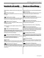
Hinweise zur sicheren MontageHinweise zur sicheren Montage
Hinweise zur sicheren MontageHinweise zur sicheren Montage
Hinweise zur sicheren Montage
Sehr geehrter Betreiber,
das Gerät darf nur durch einen Krankenhaustechni-
ker oder vergleichsweise qualifiziertes Fachpersonal
montiert werden.
Als Fachpersonal gelten Personen:
- Die ihre Kenntnisse durch eine fachliche Ausbildung
im medizinischen bzw. medizinisch-technischen Be-
reich erworben haben,
- Die von Ihnen ausgeübte Tätigkeit aufgrund beruflicher
Erfahrung und Unterweisung in die sicherheitsrelevan-
ten Bestimmungen beurteilen und mögliche Gefahren
bei der Arbeit erkennen können.
- In Staaten, in denen die Ausübung einer Tätigkeit im
medizinischen bzw. medizinisch-technischen Bereich
zertifiziert ist, setzt die Einstufung als Fachpersonal eine
entsprechende Zulassung voraus.
Sehr geehrter Monteur,
Bitte lesen sie diese Montageanweisung sehr sorgfältig
und beachten Sie die Sicherheitshinweise und Anforde-
rungen dieser Montageanweisung.
Beim Auftreten besonderer Probleme, die in dieser Mon-
tageanweisung nicht ausführlich genug behandelt werden,
wenden Sie sich zur Ihrer eigenen Sicherheit bitte an Ih-
ren Lieferanten.
Eine Änderung des Produktes ist nicht erlaubt.
Instructions for safe assemblyInstructions for safe assembly
Instructions for safe assemblyInstructions for safe assembly
Instructions for safe assembly
Dear user,
The equipment may only be assembled by a hospital
technician or a comparably qualified person.
The following persons shall be considered as quali-
fied personnel:
- Persons who underwent special professional training
in the field of medicine or medical engineering,
- Persons who can assess their work and recognise the
potential hazards involved on the basis of their profes-
sional experience and instruction in safety-relevant re-
gulations.
- In States where the performance of tasks in the medi-
cal or medical engineering sector are subject to certifi-
cation, qualified personnel must have obtained the cor-
responding certificate.
Dear installer,
Please read these installation instructions very carefully
and follow the safety instructions and requirements of the-
se installation instructions.
If there are any peculiar problems that have not been tre-
ated in sufficient detail in these installation instructions,
please contact your supplier for your own safety.
Changes to the product are not permitted.

Seite / Page 4
38628, Edition / Ausgabe 2012-05, Version 5
DeutschEnglish
Hinweise zur sicheren MontageHinweise zur sicheren Montage
Hinweise zur sicheren MontageHinweise zur sicheren Montage
Hinweise zur sicheren Montage
Zweckbestimmung:
• Die Acrobat-Geräte dienen zum Tragen und Positio-
nieren von medizinischen Untersuchungsleuchten und
Flachbildschirmen sowie der Versorgung der Geräte
mit Strom. Je nach Transformatorversion stehen z.B.
13,2V, 13,5V, 14V, 24V (ohne Transformator, 230V);
50/60Hz zur Verfügung (nicht wahlweise einstellbar).
• Die Geräte sind für Dauerbetrieb geeignet.
• Die Geräte dürfen - je nach Ausführung - nicht über
ihre auf dem Typenschild angegebene Maximallast hi-
naus belastet werden (siehe Kapitel 6 „Endgeräte mon-
tieren“).
Bestimmungswidriger Gebrauch
• Das Gerät und dessen Komponenten dürfen nicht über
die maximale Nutzlast gemäß den Angaben im “Kapi-
tel 9, Technische Daten” belastet werden.
Kontraindikation
• Das Tragarmsystem Acrobat Swing darf nicht in der
Nähe von starken Magnetfeldern eingesetzt werden.
• An das Tragarmsystem dürfen keine Anwendungsteile
des Typs BF bzw. CF gemäß IEC 60601-1 unmittelbar
angeschlossen werden.
Instructions for safe assemblyInstructions for safe assembly
Instructions for safe assemblyInstructions for safe assembly
Instructions for safe assembly
Intended purpose:
• The Acrobat appliances have been designed for the
carrying and positioning of medical examination lamps
and flat screens and also for the power supply of the
devices. Depending on the transformer version, e.g.
13,2V, 13,5V, 14V, 24V (without transformer, 230V),
50/60Hz are available (not optionally adjustable).
• The appliance is suitable for continuous operation.
• The maximum load indicated on the rating plate of the
individual appliance version must not be exceeded (see
Chapter 6 "Mounting the end device").
Incorrect use
• The maximum loading capacity of the appliance and
its components as specified in “Chapter 9, Technical
Data” must not be exceeded.
Contraindications
• The ACROBAT Swing pendant system must not be
used close to strong magnetic fields.
• No BF or CF application parts in accordance with IEC
60601-1 may be directly connected to the pendant sys-
tem.

Seite / Page 5
38628, Edition / Ausgabe 2012-05, Version 5
DeutschEnglish
Hinweise zur sicheren MontageHinweise zur sicheren Montage
Hinweise zur sicheren MontageHinweise zur sicheren Montage
Hinweise zur sicheren Montage
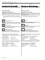
Ergänzende Bildzeichen zu den Sicherheitshinweisen:
Stromschlag:
Warnt vor einem elektrischen Stromschlag, der zu schwe-
ren Verletzungen oder sogar zum Tod führen kann.
Abstürzen des Tragarmsystems:
Warnt vor dem plötzlichen Abstürzen des Tragarmsystemes
durch Überschreiten der maximalen Nutzlast.
Hochschnellen des Federarmes:
Warnt vor dem plötzlichen Hochschnellen des Federarmes
beim Demontieren des Endgerätes.
Bildzeichen am Gerät und / oder der Verpackung:
Gebrauchsanweisung befolgen:
Lesen Sie diese Gebrauchsanweisung sorgfältig vor dem
ersten Gebrauch des Tragarmsystemes. Dadurch nutzen Sie
alle Vorteile, die das Tragarmsystem bietet und vermeiden
mögliche Verletzungen und Sachschäden.
Maximale Nutzlast beachten:
Warnt vor dem Überschreiten der zugelassenen maximalen
Nutzlast (Zuladung) am Tragarmsystem, der Adaption oder
dem Endgerät (z.B. Flachbildschirm, Untersuchungs-Leuch-
ten, etc.).
CE-Kennzeichnung:
Ondal erklärt, dass die Produkte den einschlägigen Bestim-
mungen der anwendbaren europäischen Richtlinien entspre-
chen.
Anerkannte cUL Komponente:
Diese Komponente ist von Underwriters Laboratories Inc.
anerkannt. Repräsentative Muster dieses Produkts wurden
von UL bewertet und erfüllen die anwendbaren Anforderun-
gen.
Instructions for safe assemblyInstructions for safe assembly
Instructions for safe assemblyInstructions for safe assembly
Instructions for safe assembly
Supplementary symbols used in the safety instruc-
tions:
Electric shock hazard:
Warns of electric shock which can lead to severe injury or
even death.
Pendant system crashing:
Warns of the risk of the pendant system suddenly crashing
because the max. loading capacity has been exceeded.
Sudden release of spring arm:
Warns that the spring arm may jump up suddenly while dis-
mantling the end device.
Graphic symbols on the appliance and/or on the pa-
ckaging:
Observe the Operating Instructions:
Read these Operating Instructions carefully prior to initial
operation of the pendant system. This ensures that you
benefit from all the advantages of the pendant system and
prevents any risk of injury or damage.
Observe the maximum loading capacity:
Warns of exceeding the maximum loading capacity (payload)
on the pendant system of the adaption or
the end device (e.g. flat screen, OR lamp, etc.).
CE mark:
Ondal declares that the products comply with the relevant
regulations set forth in the applicable European Directives.
Recognised cUL component:
This component has been recognised by Underwriters
Laboratories Inc. Representative samples of this product
have been reviewed by UL and comply with the applicable
requirements.

Seite / Page 6
38628, Edition / Ausgabe 2012-05, Version 5
DeutschEnglish
Hinweise zur sicheren MontageHinweise zur sicheren Montage
Hinweise zur sicheren MontageHinweise zur sicheren Montage
Hinweise zur sicheren Montage
Montage / Demontage:
VORSICHT - Stromschlag:
Um das Risiko eines elektrischen Schlages zu vermeiden,
darf das Gerät nur an ein Versorgungsnetz mit Schutzleiter
angeschlossen werden.
• Das Gerät muss so angeschlossen werden, dass es allpo-
lig und gleichzeitig vom Netz getrennt werden kann.
Luftdruck:
Zeigt die zugelassenen Luftdruckwerte von 500 hPa bis 1060
hPa für den Transport und die Lagerung.
Luftfeuchte:
Zeigt die zugelassenen Luftfeuchtewerte von 10 % bis 75
% für den Transport und die Lagerung.
Umgebungstemperatur:
Zeigt die zugelassenen Umgebungstemperaturen von
-25 °C bis 70 °C für den Transport und die Lagerung.
Umgebungsbedingungen für die Lagerung und den
Transport
Bis 15 Wochen gelten folgende Lagerbedingungen:
Umgebungstemperatur: -25 °C bis 70 °C;
Relative Feuchte: 10 % bis 75 %;
Luftdruck: 500 hPa bis 1060 hPa.
Lagerung nur in geschlossenen Räumen, danach gelten
die Werte der Umgebungsbedigungen für den Betrieb.
Umgebungsbedingungen für den Betrieb
Umgebungstemperatur: 10 °C bis 40 °C;
Relative Feuchte: 30 % bis 75 %;
Luftdruck: 700 hPa bis 1060 hPa.
Instructions for safe assemblyInstructions for safe assembly
Instructions for safe assemblyInstructions for safe assembly
Instructions for safe assembly
Mounting / dismantling:
CAUTION - Electrical shock:
To prevent the risk of electric shock, the appliance must be
connected to a supply network with a protective conduc-
tor.
• The appliance must be connected in such a way that it can
be disconnected from the mains at all poles and at the same
time.
Atmospheric pressure:
Indicates the permissible atmospheric pressure values in
a range from 500 hPa to 1060 hPa for transport and storage.
Relative humidity:
Indicates the permissible humidity values in a range from
10% to 75% for transport and storage.
Ambient temperature:
Indicates the permissible ambient temperature values in a
range from -25 °C to 70 °C for transport and storage.
Ambient conditions for storage and transport
The following storage conditions apply for storage times
of up to 15 weeks:
Ambient temperature: -25 °C to 70 °C;
Relative humidity: 10 % to 75 %;
Atmospheric pressure: 500 hPa to 1060 hPa.
Store only in indoor rooms; after this time, the values spe-
cified for the ambient conditions for operation apply.
Ambient conditions for operation
Ambient temperature: 10 °C to 40 °C;
Relative humidity: 30 % to 75 %;
Atmospheric pressure: 700 hPa to 1060 hPa.

Seite / Page 7
38628, Edition / Ausgabe 2012-05, Version 5
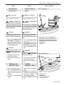
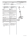
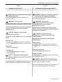
Figure / Abbildung 1
1 Anti-static rollers with brakes 2x
Antistatische Rollen mit Bremsen 2x
2 Ring cable lug of the PA cable 2X
Ringkabelschuh der PA-Leitung 2x
3 Tripod base
Stativfuß
DeutschEnglish Figure / Abbildung
1 Adhesive foil
Klebefolie
2 Clear protective foil
Klare Schutzfolie
Figure / Abbildung 2
1 Rollen montieren
Abb. 1
HINWEIS – Versionen:
Bei der Ausführung Stativfuß 6,5kg
entfallen die Erdungsleitungen.
WARNUNG - Statische Auf-
ladung:
Ohne Montage der PA-Leitung
kann es zur statischen Aufladung
des Stativgerätes und zur Ablei-
tung auf Patienten kommen. Die
PA-Leitung montieren.
VORSICHT:
Die gebremsten Rollen immer di-
agonal anbringen (siehe Abb. 1),
da sonst Kipp-/Rutschgefahr be-
steht!
1. Zwei antistatische Rollen
mit Bremsen (1) durch den
Ringkabelschuh der PA-Lei-
tung (2) führen und vollstän-
dig in den Stativfuß (3) stek-
ken.
VORSICHT:
Der Stativfuß ohne Zusatzgewicht
darf nur für 1-2 kg schwere Endge-
räte verwendet werden.
2. Zwei Rollen ohne Bremsen
vollständig einstecken.
3. Sicheren Sitz der Rollen prü-
fen.
1 Mounting the
rollers Fig. 1
NOTE – Versions:
For the 6.5kg tripod base version, no
earthing cables are required.
WARNING - Static charge
If the PA-cable is not installed, the
tripod base equipment may get
statically charged and the charge
may get transferred to the patient.
Install the PA-cable.
CAUTION:
The braked rollers must always be
installed diagonally (see Fig. 1) in
order to prevent tilting/slipping!
1. Guide two anti-static rollers
with brakes (1) through the
ring cable lug of the PA ca-
ble (2) and insert completely
in the tripod base (3).
CAUTION:
The tripod base should be used
without additional weight only for
end devices that weigh 1-2 kg.
2. Completely insert the two
rollers without brakes.
3. Check for firm seating of the
rollers.
2 Farbfolie
aufkleben Abb. 2
1. Augenförmige Vertiefung rei-
nigen.
2. Klebefolie (1) abziehen,
Farbfolie in die augenförmige
Vertiefung einlegen und
gleichmäßig andrücken.
3. Klare Schutzfolie (2) abzie-
hen.
2 Sticking on the
color foil Fig. 2
1. Clean eye-shaped recess.
2. Pull out the adhesive foil (1),
place the color foil in the eye-
shaped recess and press it
uniformly.
3. Pull off the clear protective
foil (2).

Seite / Page 8
38628, Edition / Ausgabe 2012-05, Version 5
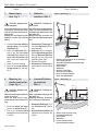
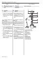
1 Screw (representation of an example)
with spring washer
Schraube (Darstellung beispielhaft)
mit Federring
2 Tripod tube
Stativrohr
3 Recess in the tube
Aussparung im Rohr
4 Nose of the tripod base
Nase des Stativfußes
DeutschEnglish Figure / Abbildung
Figure / Abbildung 4
1 Plastic semi-circular rings
Kunststoff-Halbringe
2 Tripod base
Stativfuss
3 Cross-slotted screw
Kreuzschlitzschrauben
Figure / Abbildung 3
3 Stativrohr
montieren Abb. 3
VORSICHT - Schäden am
Gerät:
Ohne Einrasten der Nasensiche-
rung und anschließendem Ver-
schrauben des Stativrohres, fällt
das Stativ um.
Nasensicherung einrasten und
Schraube mit Federring fest anzie-
hen.
1. Schraube mit Federring (1)
aus dem Stativrohr (2) her-
ausschrauben.
2. Stativrohr (2) so einsetzen,
daß die Aussparung im Rohr
(3) in der Nase des Stativfus-
ses (4) sitzt und nicht mehr
gedreht werden kann.
3. Sicheren Sitz prüfen.
4. Schraube mit Federring (1)
einschrauben und fest anzie-
hen.
3 Mount tripod
tube Fig. 3
CAUTION - Damage to the
equipment:
If the nose fastening is not inser-
ted properly, and then the tripod
tube has not been bolted, the tri-
pod can fall.
Engage the nose fastening and
tighten the screw with a spring
washer.
1. Unscrew the screw with the
spring washer (1) from the
tripod tube (2).
2. Insert the tripod tube (2) in
such a way that the recess
in the tube (3) is seated in the
nose of the tripod base (4)
and cannot be rotated any
more.
3. Check for secure seating.
4. Screw in the screw with the
spring washer (1) and tigh-
ten it.
4 Kunststoff-Halbrin-
ge montieren
Abb. 4
VORSICHT - Schäden am
Gerät:
Ohne eingesetzte Halbringe, fällt
das Stativ um.
Halbringe einsetzen, Verschrau-
ben und sicheren Sitz prüfen.
1. Kunststoff-Halbringe (1) in
den Stativfuss (2) eindrük-
ken.
2. Kreuzschlitzschrauben (3)
eindrehen und sicheren Sitz
prüfen.
4 Mounting the
plastic semicircular
rings Fig. 4
CAUTION - Damage to the
equipment:
Without the half rings inserted, the
tripod will tip over.
Insert the semi-circular rings,
screw them and check secure fit-
ting.
1. Press the plastic half rings
(1) into the tripod base (2).
2. Turn in the cross-slotted
screw (3) and check whether
it is tight.

Seite / Page 9
38628, Edition / Ausgabe 2012-05, Version 5
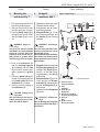
DeutschEnglish Figure / Abbildung
Figure / Abbildung 5
1 Name plate
Typenschild
2 Spring arm
Federarm
5 Mounting the spring
arm
5.1 Align the spring arm
with the tripod base
Fig. 5
NOTE:
The spring force of the spring arm
and the tripod base is designed
for load torque maximum 39 Nm.
The weight category of the spring
arm can be seen on the name
plate (1).
The weighted tripod base can be
recognized from the additional
weight (metal plate) on the under-
side.
CAUTION - Damage to the
equipment:
The tripod can tip over, when the
tripod base is without additional
weight and the load torque is gre-
ater than 18 Nm.
The spring arm for load torque
greater than 18 Nm should only be
installed with a weighted tripod
base.
1. Determine the weight catego-
ry on the name plate (1).
2. Mount the spring arm accor-
ding to the chapter 5.2, „As-
sembly“.
5 Federarm
montieren
5.1 Federarm dem Stativ-
fuß zuordnen
Abb. 5
HINWEIS:
Die Federkraft des Federarmes
und der Stativfuß ist für Lastmo-
mente bis maximal 39 Nm aus-
gelegt. Die Gewichtkategorie des
Federarmes entnehmen Sie dem
Typenschild (1).
Der beschwerte Stativfuß ist am
Zusatzgewicht (Metallplatte) an
der Unterseite erkennbar.
VORSICHT - Schäden am
Gerät:
Das Stativ kann umfallen wenn der
Stativfuß ohne Zusatzgewicht
ausgestattet ist und das Lastmo-
ment am Federarm größer als 18
Nm ist.
Der Federarm für das Lastmoment
größer 18 Nm darf nur mit einem
beschwerten Stativfuß montiert
werden.
1. Gewichtskategorie am Typen-
schild (1) feststellen.
2. Federarm gemäß Kapitel 5.2,
"Montage" montieren.

Seite / Page 10
38628, Edition / Ausgabe 2012-05, Version 5
DeutschEnglish Figure / Abbildung
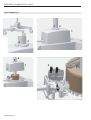
Figure / Abbildung 6
1 Cross-slotted screw
Kreuzschlitzschraube
2 Cover
Abdeckkappe
3 Spring arm pin
Federarmzapfen
4 Disk
Scheibe
5 Retaining ring
Sicherungsring
6 Plug-socket joint
Steckverbindung
5 Mounting the spring
arm
5.2 Assembly
Fig. 6
1. Unscrew the cross-slotted
screw (1), pull the cover (2)
forward and move it upward
to take it out.
CAUTION - Damage to the
equipment:
Without the disk installed, the re-
taining ring gets loosened and the
spring arm falls out of the joint.
- Always install the disk.
2. Insert the spring arm pin (3),
place the disk (4) and secure
them with the retaining ring
(5).
3. The retaining ring (5) must
fit into the pin groove. This
must be checked.
4. Make the electrical connec-
tion (6).
5. Put on the cover (2) and
screw it fast with the cross-
slotted screw (1).
5 Federarm
montieren
5.2 Montage
Abb. 6
1. Kreuzschlitzschraube (1)
herausschrauben und Ab-
deckkappe (2) nach vorne
ziehen und nach oben abneh-
men.
VORSICHT - Schäden am
Gerät:
Ohne montierte Scheibe wird der
Sicherungsring aufgedreht und
der Federarm fällt aus der Anbin-
dung.
- Immer die Scheibe montieren.
2. Federarmzapfen (3) einstek-
ken, Scheibe (4) auflegen
und mit dem Sicherungsring
(5) sichern.
3. Der Sicherungsring (5) muß
in die Zapfennut einrasten.
Dies ist zu überprüfen.
4. Elektrische Steckverbindung
(6) herstellen.
5. Abdeckkappe (2) aufsetzen
und mit der Kreuzschlitz-
schraube (1) verschrauben.

Seite / Page 11
38628, Edition / Ausgabe 2012-05, Version 5
DeutschEnglish Figure / Abbildung
Figure / Abbildung 7
1 Plastic sleeve
Kunststoffhülse
2 Slot
Schlitze
3 End-device
Endgerät
4 Securing segment
Sicherungssegment
5 Groove
Nut
6 Brake screw
Bremsschraube
6 Mounting the
end-device Fig. 7
1. Pull out the plug and secure it
from being inserted again.
2. Take out the protective cover
from the spring arm opening.
3. Push the plastic sleeve (1) on
the spring arm in such a way
that the slots (2) get cover-
ed.
WARNINIG - Danger of
injury:
The spring arm, which is pressed
downwards, can jump backwards
and result in injuries. During the
installation of the end-device, no-
body should be present within
swiveling range of the spring arm.
4. Push in the end-device (3)
and the securing segment
(4) completely into the slots
(2), so that the securing seg-
ment is guided in the groove
(5).
5. Rotate the plastic sleeve (1)
through 180 degrees and turn
in the brake screw (5) till the
end-device (3) is braked.
6. Check the secure seating of
the end-device (3).
CAUTION - Damage to the
equipment:
After the end-device has been in-
stalled, perform tilt test in accor-
dance with DIN EN 60601-1.
6 Endgerät
montieren Abb. 7
1. Netzstecker ziehen und gegen
Wiedereinstecken sichern.
2. Schutzkappe aus der Feder-
armöffnung nehmen.
3. Kunststoffhülse (1) so auf
den Federarm schieben, daß
die Schlitze (2) zur Deckung
kommen.
WARNUNG - Verletzungs-
gefahr:
Der nach unten gedrückte Feder-
arm kann hochschnellen und zu
Verletzungen führen.
Während der Montage des Endge-
rätes dürfen sich keine Personen
im Schwenkbereich des Federar-
mes aufhalten.
4. Endgerät (3) einschieben und
Sicherungssegment (4) voll-
ständig in den Schlitz (2) ein-
stecken, so daß das Siche-
rungssegment in der Nut (5)
geführt wird.
5. Kunststoffhülse (1) um 180-
Grad drehen und Brems-
schraube (5) solange eindre-
hen bis das Endgerät (3) ge-
bremst wird.
6. Sicheren Sitz des Endgerätes
(3) prüfen.
VORSICHT - Schäden am
Gerät:
Nach der Montage des Endgerätes
Kipptest gemäß DIN EN 60601-1
durchführen.

Seite / Page 12
38628, Edition / Ausgabe 2012-05, Version 5
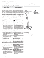
Figure / Abbildung 8
DeutschEnglish Figure / Abbildung
7 Adjusting the spring
force Fig. 8
Like every technical component,
springs are subjected to natural
wear. Thus, the spring force may
give way and reduce after long ope-
ration, and has to be re-adjusted.
Adjust the spring force in such
a way that, the spring arm with
end device comes to a stand-
still in every desired position.
CAUTION - Destruction
of the spring arm:
The spring tension is adjusted in
the upper end position.
1. Remove the left-hand joint cover
half (2) from the spring arm
(when looking from the end de-
vice). To do this, gently push the
joint cover half out of the groove
in the spring arm joint using a
small slotted screwdriver.
2. Move the end device to the upper
end position.
3. Insert the slotted screwdriver into
the drill hole (1) and adjust the
spring tension.
4. Mount the joint cover and make
sure that it snaps into place.
CAUTION - Destruction of
the spring arm:
Driving in the brake screw too
deeply destroys the spring arm.
Tighten the brake screw with care
while continually checking the
braking force.
If the spring arm drops - the
spring force is too low.
- The adjusting screw must be ro-
tated to the left (in the counter-
clockwise direction).
If the spring arm goes upward -
the spring force is too high:
- the adjusting screw must be ro-
tated to the right (in the clockwi-
se direction).
7 Federkraft
einstellen Abb. 8
Wie jedes technisches Bauteil unter-
liegen Federn einem natürlichen
Verschleiß. So kann die Federkraft
nach längerem Betrieb nachlassen
und muß nachgestellt werden.
Federkraft so einstellen, daß
der Federarm mit Endgerät in
jeder gewünschten Position
stehen bleibt.
VORSICHT - Zerstörung
des Federarmes:
Die Einstellung der Federkraft er-
folgt in der oberen Endstellung.
1. Die aus Richtung des Endgerä-
tes linke Gelenkverkleidung (2)
am Federarm abnehmen. Dazu
die Gelenkverkleidung mit einem
schmalen Schlitzschraubendre-
her vorsichtig aus der Nut im Fe-
derarmgelenk heraushebeln.
2. Endgerät in die obere Endstel-
lung bringen.
3. Schlitzschraubendreher in die
Bohrung (1) stecken und Feder-
kraft einstellen.
4. Gelenkverkleidung montieren und
einrasten.
VORSICHT - Zerstörung
des Federarmes:
Beim zu tiefen Eindrehen der
Bremsschraube wird der Feder-
arm zerstört. Bremsschraube nur
vorsichtig unter wiederholter Kon-
trolle der Bremskraft eindrehen.
Sinkt der Federarm ab - ist die
Federkraft zu gering:
- die Einstellschraube muß nach
links ( gegen den Uhrzeigersinn)
gedreht werden.
Steigt der Federarm nach oben-
ist die Federkraft zu hoch:
- die Einstellschraube muß nach
rechts (im Uhrzeigersinn) ge-
dreht werden.
1 Drill hole
Bohrung
2 Joint cover half spring arm
Gelenkverkleidung Federarm

Seite / Page 13
38628, Edition / Ausgabe 2012-05, Version 5
DeutschEnglish
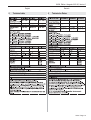
8 Change the fuses Fig. 9
NOTE - Built-in overload protection for versions
with toroidal transformer:
To protect the transformer and the end device, the
fuses are installed.
WARNING - Electrical shock:
For all maintenance work, switch off the equipment, pull out
the main plug and secure it form being switched on again.
The technical specification for the fuses can be found
on page 14 of this document and on the label
inside the cover.
CAUTION - Damage to the Equipment
Apply only the specified fuses.
Change the fuses corresponding to the following
steps:
Open the cover
1. Loosening the screw (3), don’t unscrew completely.
2. Push up clamp ring (2) and cover (1) and secure them.
Change fuse
3. Change broken fuse (4).
Close the cover
4. Push down clamp ring (2) and cover (1).
5. Tighten screw (3).
NOTE - To replace the connecting cable:
The connecting cable may only be replaced by an installer
authorised by Ondal.
Circuit diagrams and more detailed information on the com-
ponents replaced are available from Ondal on request.
8 Austausch der Sicherungen Abb. 9
HINWEIS - Eingebauter Überlastungsschutz bei
Ausführungen mit Ringkerntransformator:
Zum Schutz des Transformators und des Endgerätes
sind Sicherungen eingebaut.
WARNUNG - Stromschlag:
Bei allen Wartungsarbeiten Gerät spannungslos
schalten, Netzstecker ziehen und gegen
Wiedereinschalten sichern.
Die technischen Daten der Sicherungen sind der
Tabelle auf Seite 14 und dem Kennzeichnungsschild
im Gehäuse zu entnehmen.
VORSICHT - Schäden am Gerät:
Es dürfen nur die vorgeschriebenen Sicherungen
verwendet werden!
Austausch der Sicherungen gemäß folgender
Arbeitsschritte:
Gehäuse öffnen
1. Schraube (3) lösen, aber nicht ganz herausdrehen.
2. Klemmring (2) und Gehäuse (1) hochschieben und
sichern.
Sicherung austauschen
3. Defekte Sicherung (4) austauschen.
Gehäuse schließen
4. Klemmring (2) und Gehäuse (1) nach unten schieben.
5. Schraube (3) anziehen.
HINWEIS - Austausch der Anschlussleitung:
Die Anschlussleitung darf nur von einem von Ondal auto-
risierten Monteur ausgetauscht werden.
Ondal stellt auf Anfrage Schaltpläne und Informationen zu
den austauschbaren Komponenten zur Verfügung.

Seite / Page 14
38628, Edition / Ausgabe 2012-05, Version 5
Figure / Abbildung 9
1
2
3
1
2
3
4
32

Seite / Page 15
38628, Edition / Ausgabe 2012-05, Version 5
DeutschEnglish
9 Technische Daten9 Technical data

No. 38628
-
 1
1
-
 2
2
-
 3
3
-
 4
4
-
 5
5
-
 6
6
-
 7
7
-
 8
8
-
 9
9
-
 10
10
-
 11
11
-
 12
12
-
 13
13
-
 14
14
-
 15
15
-
 16
16


Hill-Rom Green Series 900 Procedure Light Installationsanleitung
- Typ
- Installationsanleitung
- Dieses Handbuch eignet sich auch für
in anderen Sprachen
Verwandte Artikel
Andere Dokumente
-
Dräger AI Polaris Multimedia (AC) ME Assembly Instruction
-
-
SICK Messradsystem für Klemmflanschencoder, Measuring wheel system for face mount flange encoder Bedienungsanleitung
-
-
-
-
 Wella Visionair M50 Operating Instructions Manual
-
