
Analysentechnik
Installation and Operation Instructions
Original instructions
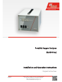
Portable Oxygen Analyser
BA 4000 Inj.
BE550004
07/2016-2
Bühler Technologies GmbH, Harkortstr. 29, D-40880 Ratingen
Tel. +49 (0) 21 02 / 49 89-0, Fax: +49 (0) 21 02 / 49 89-20
E-Mail: [email protected]
Internet: www.buehler-technologies.com

Bühler Technologies GmbH, Harkortstr. 29, D-40880 Ratingen
Tel. +49 (0) 21 02 / 49 89-0, Fax: +49 (0) 21 02 / 49 89-20
Internet: www.buehler-technologies.com
E-Mail: [email protected]
Read this instruction carefully prior to installation and/or use. Pay at-
tention particularly to all advises and safety instructions to prevent in-
juries. Bühler Technologies can not be held responsible for misusing
the product or unreliable function due to unauthorised modifications.
All rights reserved. Bühler Technologies GmbH 2017
Document information
Document No..........................................................BE550004
Version......................................................................07/2016-2

BA 4000 Inj.
Contents
1 Introduction..................................................................................................................................................................................................................... 2
1.1 Intended Use.........................................................................................................................................................................................................2
1.2 Design types.......................................................................................................................................................................................................... 2
1.3 Ordering instructions ........................................................................................................................................................................................ 2
1.4 Functional principle ........................................................................................................................................................................................... 2
1.5 Scope of delivery..................................................................................................................................................................................................2
2 Safety instructions......................................................................................................................................................................................................... 3
2.1 Important notices................................................................................................................................................................................................ 3
2.2 General hazard warnings .................................................................................................................................................................................4
3 Transport and storage .................................................................................................................................................................................................. 5
4 Installation and connection ........................................................................................................................................................................................6
4.1 Installation site requirements.........................................................................................................................................................................6
4.2 Electrical connections ........................................................................................................................................................................................6
4.3 Sample gas supply ..............................................................................................................................................................................................6
4.4 Gas connections................................................................................................................................................................................................... 7
5 Operation and Control..................................................................................................................................................................................................8
5.1 Calibration.............................................................................................................................................................................................................8
5.1.1 Test gases for calibration .................................................................................................................................................................. 9
5.1.2 Calibration for BA 4000 Inj. GV ....................................................................................................................................................... 9
5.1.3 Calibration for BA 4000 Inj. KV.......................................................................................................................................................10
5.1.4 Carrier gas influence (cross-sensitivity).......................................................................................................................................10
5.2 Notes on operating the BA 4000 Inj. KV/D with pressure gauge (optional) ...................................................................................10
5.3 Performing the measurement .......................................................................................................................................................................11
6 Service...............................................................................................................................................................................................................................12
6.1 Replacing the rechargeable battery............................................................................................................................................................. 12
7 Service and repair..........................................................................................................................................................................................................13
7.1 Troubleshooting .................................................................................................................................................................................................13
7.2 Spare parts and accessories ............................................................................................................................................................................13
8 Disposal............................................................................................................................................................................................................................15
9 Appendix......................................................................................................................................................................................................................... 16
9.1 Technical Data.................................................................................................................................................................................................... 16
9.2 Puncture devices ................................................................................................................................................................................................17
9.3 Flow charts ...........................................................................................................................................................................................................17
10 Attached documents................................................................................................................................................................................................... 18
iBühler Technologies GmbHBE550004 ◦ 07/2016-2

BA 4000 Inj.
1 Introduction
1.1 Intended Use
The portable BA 4000 Inj. Bühler O
2
analyser is a special unit for determining oxygen in low gas volumes.
This analyser is a modification of the BA4000, primarily used in the food industry to analyse small residual amounts in modi-
fied atmosphere packaging, bottles or tins. The O
2
content in insulating glass panes can also be determined. There are 2 ver-
sions.
The device
must not be used
– To analyse combustible, inflammable or explosive gas mixtures,
– In explosive areas and
– For applications where equipment failure or malfunction puts persons in immediate danger.
1.2 Design types
The
BA 4000 Inj. GV
is used for volumes > 35 ml. The duration of the internal sample gas pump can optionally be controlled us-
ing an adjustable timing relay.
The
BA 4000 Inj. KV
is used for gas volumes < 35 ml. This analyser is operated by a vacuum pump. There are different puncturing
devices available, depending on the type of packaging.
An optional pressure gauge is available for use with vacuum packaging. This allows for comparing O
2
concentrations at differ-
ent package pressures. It further allows for zero point calibration without zero gas.
1.3 Ordering instructions
Device model
Item no. Description
55 11 399 BA 4000 Inj. GV
55 11 5991 BA 4000 Inj. KV
1.4 Functional principle
The measuring cell on the analyser uses the handle principle, utilising the paramagnetic properties of oxygen. In practice, the
quality of gas conditioning and the mechanical strain (impact, shock) limit the life of the measuring cell.
The
BA4000Inj.GV
is designed as a portable unit and can be used for monitoring changing locations.
1.5 Scope of delivery
– Analyser
– Product documentation
– Connection/mounting accessories (optional)
2 Bühler Technologies GmbH BE550004 ◦ 07/2016-2

BA 4000 Inj.
2 Safety instructions
2.1 Important notices
Operation of the device is only valid if:
– the product is used under the conditions described in the installation- and operation instruction, the intended application
according to the type plate and the intended use. In case of unauthorized modifications done by the user Bühler Technolo-
gies GmbH can not be held responsible for any damage,
– when complying with the specifications and markings on the nameplates.
– the performance limits given in the datasheets and in the installation- and operation instruction are obeyed,
– monitoring devices and safety devices are installed properly,
– service and repair is carried out by Bühler Technologies GmbH,
– only original spare parts are used.
This manual is part of the equipment. The manufacturer keeps the right to modify specifications without advanced notice. Keep
this manual for later use.
Please particularly note the following analyser instructions:
– Always transport the equipment diligently and carefully. Strong impact and shock may damage the measuring cells in the
analyser or shorten their life!
– Disconnect from the mains before opening the unit.
–
BA4000Inj.GV: This unit has a 12 V battery, which is always energised.
Signal words for warnings
DANGER
Signal word for an imminent danger with high risk, resulting in severe injuries or death if not avoided.
WARNING
Signal word for a hazardous situation with medium risk, possibly resulting in severe injuries or death if not
avoided.
CAUTION
Signal word for a hazardous situation with low risk, resulting in damaged to the device or the property or
minor or medium injuries if not avoided.
NOTICE
Signal word for important information to the product.
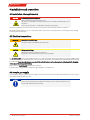
Warning signs
In this manual, the following warning signs are used:
Warning against hazardous situations General notice
Warning against electrical voltage Disconnect from mains
Warning against respiration of toxic gases Wear respirator
Warning against acid and corrosive substances Wear eye/face protection
Warning against potentially explosive atmospheres Wear protection gloves
Warning against hot surface
3Bühler Technologies GmbHBE550004 ◦ 07/2016-2

BA 4000 Inj.
2.2 General hazard warnings
Installation of the device shall be performed by trained staff only, familiar with the safety requirements and risks.
Check all relevant safety regulations and technical indications for the specific installation place. Prevent failures and protect
persons against injuries and the device against damage.
The operator of the system must secure that:
– safety and operation instructions are accessible and followed,
– local safety regulations and standards are obeyed,
– performance data and installation specifications are regarded,
– safety devices are installed and recommended maintenance is performed,
– national regulations for disposal of electrical equipment are obeyed.
Maintenance, Repair
Please note during maintenance and repairs:
– Repairs to the unit must be performed by Bühler authorised personnel.
– Only perform conversion-, maintenance or installation work described in these operating and installation instructions.
– Always use genuine spare parts.
Always observe the applicable safety and operating regulations in the respective country of use when performing any type of
maintenance.
DANGER Electrical voltage
Electrocution hazard.
a) Disconnect the device from power supply.
b) Make sure that the equipment cannot be reconnected to mains unintentionally.
c) The device must be opened by trained staff only.
d) Regard correct mains voltage.
DANGER Toxic, acidic gasses
Sample gas / calibrating gas can be harmful.
a) If necessary, ensure a safe gas discharge.
b) Switch off the gas supply before performing maintenance and protect from opening
inadvertently.
c) Protect yourself from toxic / corrosive gasses when performing maintenance. Wear
appropriate protective equipment.
DANGER Potentially explosive atmosphere
Explosion hazard if used in hazardous areas.
The device is not suitable for operation in hazardous areas with potentially explosive at-
mospheres.
Do not expose the device to combustible or explosive gas mixtures.
4 Bühler Technologies GmbH BE550004 ◦ 07/2016-2

BA 4000 Inj.
3 Transport and storage
Transport
The unit is sensitive to shock and vibration. Therefore, where possible, transport in the original packaging or large, sturdy pack-
aging at a minimum consisting of 3 layer carton, plastic or aluminium sheet. Line the inside of the packaging with padding at
least 10 cm thick on all sides.
The unit should be marked fragile for shipping.
Removal from service and storage
Purge the unit with dry nitrogen or dry air before removing from service for extended periods. Then close the gas inputs and
outputs to prevent dirt, dust and moisture from entering the unit.
Store the unit in a dry, ventilated, dust-free room. Cover the unit with suitable packaging to protect it from liquids and dirt.
Storage temperature: -20°C … +50°C
5Bühler Technologies GmbHBE550004 ◦ 07/2016-2

BA 4000 Inj.
4 Installation and connection
4.1 Installation site requirements
DANGER Potentially explosive atmosphere
Explosion hazard if used in hazardous areas.
The device is not suitable for operation in hazardous areas with potentially explosive at-
mospheres.
Do not expose the device to combustible or explosive gas mixtures.
This unit is intended for use in protected rooms. If necessary, protect from the weather when used outdoors.
The analyser should only be set up on a solid, stable surface. In the event of strong vibration or shock nearby, provide a highly
cushioning intermediate layer.
4.2 Electrical connections
WARNING Hazardous electrical voltage
The device must be installed by trained staff only.
CAUTION Wrong mains voltage
Wrong mains voltage may damage the device.
Regard the correct mains voltage as given on the type plate.
The
BA4000Inj. GV
can be operated without mains access after adequately charging the built-in storage battery. Only use the
included plug-in charger. The charging time varies based on the level of the rechargeable battery. When fully drained it should
be at least 15 h.
Please keep the charger connected if the unit will not be used for extended periods (battery trickle charging).
Never exhaust the rechargeable battery.
Only operate the
BA4000Inj KV
with the plug-in charger.
Verify the plug-in charger matches the power supply available on site before use.
4.3 Sample gas supply
The sample gas supply should use the same sample gas path as during measurement. Most importantly, the pressure, temper-
ature and flow rate should be the same.
NOTICE
Please note, any change in the temperature and air pressure compared over the last cal-
ibration will change the measurements.
6 Bühler Technologies GmbH BE550004 ◦ 07/2016-2

BA 4000 Inj.
4.4 Gas connections
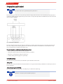
The sample gas inlet is located in the front panel and uses a M6x0.75 hose connection.
The sample gas outlet is located at the back of the unit in form of a hose coupling. With built-in sample gas pump the primary
pressure must not exceed max. 5mbar.
Fig.1: Front view
7Bühler Technologies GmbHBE550004 ◦ 07/2016-2

BA 4000 Inj.
5 Operation and Control
NOTICE
The device must not be operated beyond its specifications.
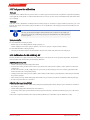
The measuring signal of the unit can be picked up via the D-Sub plug at the back of the unit. The following image shows the as-
signment. In addition, the mA output for the pressure indicator can be picked up (4-20mA = 0-1100mbar). The max. load for the
optional output is 300Ohm.
Output
0-1 V
Output
4-20 mA
Fig.2: D-Sub plug configuration
The unit is calibrated at the factory. However, the calibration can change due to the ageing process and environmental condi-
tions. These changes in the measuring performance is called drift. The calibration should therefore be checked before every
series of measurements to eliminate measuring errors.
The unit should be calibrated in the following cases:
– with every initial operation, after the warm-up period
– after great changes in the barometric pressure (changes in weather)
– when the room temperature changes more than 5°C
– routinely during operation (approx. 1x per month)
5.1 Calibration
Since the measuring system is linear, two calibration points will suffice for the check:
-Zero point
The zero point corresponds with the measurement if there is no oxygen in the measuring cell and there is neutral gas such as ni-
trogen in the unit.
-Measuring range (sensitivity)
The sensitivity for the measuring range is set with span gas or ambient air (~20.9%O
2
).
NOTICE
Calibration can only be performed with stagnant gas.
8 Bühler Technologies GmbH BE550004 ◦ 07/2016-2

BA 4000 Inj.
5.1.1 Test gases for calibration
-Zero gas
Zero gas is used to calibrate the zero point. It must not contain oxygen and should not be susceptible to magnetism. Depending
on the application, nitrogen N
2
or carbon dioxide CO
2
can be used as zero gas. The selector switch at the back of the unit must be
set accordingly.
-Span gas
Span gas is used to calibrate the sensitivity (in the measuring range). It is a mixture of oxygen and the respective zero gas or am-
bient air. The oxygen content of the span gas should be as close to the O
2
ratio of the sample gas. However, it should not be less
than 15Vol.%.
NOTICE
The span gas should preferably be added under the same conditions as the sample gas.
When using sample gas conditioning, the span gas should therefore be added upstream
from this system.
Span gas supply:
For units with built-in sample gas pump:
– Add the span gas via T-fitting with the sample gas pump on.
– Set the output pressure on the span gas cylinder so an excess of span gas is dispersed at the T-fitting.
For units without built-in sample gas pump:
– The span gas should be added to the unit with the same pressure and the same flow rate as the sample gas.
5.1.2 Calibration for BA 4000 Inj. GV
The unit should be on for approx. 30min. before calibrating it so all components are at operating temperature. The puncture
device should be removed from the gas inlet during calibration.
Adjusting the zero point
– Switch on the pump using the pump/valve switch.
– Connect a hose to the gas inlet. Connect the test gas cylinder and set the pressure regulator on the cylinder to max. 0.1bar
overpressure.
Use the same anaerobic gas (N
2
or CO
2
) as the zero gas used to gas the packaging to be tested. Set the toggle switch at the
back of the unit to the corresponding setting.
– Slowly open the valve on the pressure regulator. If the reading on the analyser’s gauge fluctuates, reduce the pressure with
the pressure regulator.
– If the reading is steady, switch off the pump, shut off the zero gas and disconnect the hose (calibration with stagnant gas).
– Use the zero potentiometer to set to 0.0%.
Adjusting the range (sensitivity)
– Connect a hose to the gas inlet. Switch on the pump using the pump/valve switch, add span gas or ambient air and wait for
the reading to stabilise.
– Switch off the pump/valve switch and disconnect the hose.
– If necessary, set the "Span" potentiometer via the front panel on the unit so the value matches the span gas (e.g. 20.9Vol.%
for air).
In the event of significant deviations from setpoint during calibration, it’s advisable to repeat calibration to verify.
9Bühler Technologies GmbHBE550004 ◦ 07/2016-2

BA 4000 Inj.
5.1.3 Calibration for BA 4000 Inj. KV
The unit should be on for approx. 30min. before calibrating it so all components are at operating temperature. The puncture
device should be removed from the gas inlet during calibration.
Setting the zero point with zero gas
Disconnect the connection hose to the vacuum pump. Switch on the pump/valve switch (1), which will open the solenoid valve.
– Connect a hose to the gas inlet. Connect the test gas cylinder and set the pressure regulator on the cylinder to max. 0.1bar
overpressure.
Use the same anaerobic gas (N
2
or CO
2
) as the zero gas used to gas the packaging to be tested. Set the toggle switch at the
back of the unit to the corresponding setting.
– Slowly open the valve on the pressure regulator. If the reading on the analyser’s gauge fluctuates, reduce the pressure with
the pressure regulator.
– If the reading is steady, set the pump/valve switch to 0, which will close the solenoid valve. Disconnect the hose (calibration
with stagnant gas).
– Use the zero potentiometer to set to 0.0%.
Adjusting the zero point via pressure gauge (optional)
With an optional pressure gauge (BA 4000 Inj. KV/D), the zero point calibration requires no zero gas. The toggle switch at the
back of the unit must be in the position corresponding with the filling gas for the packaging.
– Attach the connection hose to the vacuum pump. Switch off the pump/valve switch, which will close the solenoid valve.
– Switch on the mbar/O
2
switch. The display will show the pressure.
– Switch on the vacuum pump.
– Once the required vacuum has been created, switch off the mbar / O
2
switch. The O
2
concentration will appear.
– Use the zero potentiometer to set to 0.0%.
Adjusting the range (sensitivity)
– Attach the connection hose to the vacuum pump. Switch on the pump/valve switch (1), which will open the solenoid valve.
– Switch on the vacuum pump, air or the span gas will be drawn in.
– Once the reading is steady, switch off the pump/valve switch, which will close the solenoid valve (calibration with stagnant
gas).
– If necessary, set the "Span" potentiometer via the front panel on the unit so the value matches the span gas (e.g. 20.9Vol.%
for air).
5.1.4 Carrier gas influence (cross-sensitivity)
The selectivity of the unit’s measuring method is based on the extreme magnetic susceptibility (measured variable for magnet-
isation) of oxygen. The magnetic susceptibility of other gases is typically so low that its influence on the measurement can be
vastly disregarded.
Significant measuring errors only occur when e.g. using nitrogen as the zero gas for calibration, but using CO
2
as the sample gas
(filling gas for the packaging) . The unit will then show a value, even if the sample gas contains no oxygen, i.e. it is cross-sensitive
to the other gas component. In this case, recalibrate with the toggle switch at the back of the unit in the correct position. If the
measurement is still incorrect, please contact Service for assistance.
5.2 Notes on operating the BA 4000 Inj. KV/D with pressure gauge (optional)
Use the mbar/O
2
switch to toggle between displaying the pressure and concentration. The pressure is displayed in mbar, the
concentration in Vol.%. So in addition to the concentration, the internal pressure for the packaging can also be displayed.
10 Bühler Technologies GmbH BE550004 ◦ 07/2016-2

BA 4000 Inj.
5.3 Performing the measurement
– Attach the needle to the puncture device.
– Apply a self-adhesive piece of rubber to the packaging.
–
BA4000Inj.KV:
Only insert the needle far enough into the piece of rubber, at an angle, to cover the side bore. Switch on the
pump/valve switch, which will open the solenoid valve. Switch on the vacuum pump and evacuate the analyser.
– Once a vacuum has been created, switch off the pump/valve switch, which will close the solenoid valve.
– Insert the needle all the way into the packaging. The residual gas in the packaging will flow into the analyser. With an op-
tional "pressure gauge", the display can be toggled between O
2
concentration and pressure (mbar/O
2
switch).
–
BA4000Inj.GV:
Insert the needle through the piece of rubber and into the packaging. Switch on the pump/valve switch,
filling gas will be drawn from the packaging.
– When the reading is steady, switch off the pump, the O
2
concentration will appear.
11Bühler Technologies GmbHBE550004 ◦ 07/2016-2

BA 4000 Inj.
6 Service
During maintenance, remember:
– The equipment must be maintained by a professional familiar with the safety requirements and risks.
– Only perform maintenance work described in these operating and installation instructions.
– When performing maintenance of any type, observe the respective safety and operation regulations.
DANGER Electric voltage
Risk of electric shock
a) Disconnect the unit from the mains when performing any maintenance.
b) Secure the equipment from accidental restarting.
c) The unit may only be maintained and opened by instructed, competent personnel.
DANGER Toxic, acidic gasses
Sample gas / calibrating gas can be harmful.
a) If necessary, ensure a safe gas discharge.
b) Switch off the gas supply before performing maintenance and protect from opening
inadvertently.
c) Protect yourself from toxic / corrosive gasses when performing maintenance. Wear
appropriate protective equipment.
The measuring cell and, if applicable, the built-in sample gas pump, are maintenance free except for occasional calibration. The
built-in protective filter in the puncture device must be checked regularly and replaced if dirty.
6.1 Replacing the rechargeable battery
BA4000Inj. GV only:
Depending on the operating and ambient conditions, the rechargeable battery will occasionally need to be replaced (typical life
approx. 4-5 years).
We recommend having the battery replaced by the factory to also have the internal gas paths and the measuring cell.
12 Bühler Technologies GmbH BE550004 ◦ 07/2016-2

BA 4000 Inj.
7 Service and repair
This chapter contains information on troubleshooting and correction should an error occur during operation.
Repairs to the unit must be performed by Bühler authorised personnel.
Please contact our Service Department with any questions:
Tel.: +49-(0)2102-498955
or your agent
If the equipment is not functioning properly after correcting any malfunctions and switching on the power, it must be inspected
by the manufacturer. Please send the equipment inside suitable packaging to:
Bühler Technologies GmbH
- Reparatur/Service -
Harkortstraße 29
40880 Ratingen
Germany
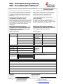
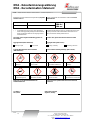
Please also attached the completed and signed RMA decontamination statement to the packaging. We will otherwise be unable
to process your repair order.
You will find the form in the appendix of these instructions, or simply request it by e-mail:
.
7.1 Troubleshooting
Problem / Malfunction Possible cause Action
No display – "Power" switch off – Toggle switch up
– Rechargeable battery in the BA4000Inj. GV
drained
– Plug in the wall power supply and connect to
the BA4000; the display must light up imme-
diately.
– Fuse at the back of the BA4000 defective – Replace fuse
The value displayed deviates
significantly from the calib-
rated value or the sample gas
measurement to be expected
– The ambient or unit temperature when
switching the unit on was far below the per-
missible value of 5°C
– Switch off the "Power" switch and switch on
again after 10sec
– If necessary, recalibrate
– Measuring system vibrates – Switch off the "Power" switch and switch on
again after 10sec
– If necessary, recalibrate
7.2 Spare parts and accessories
Item no. Description Recommended for 2 years of
service
55 07 09 91 Measuring cell -
55 05 99 910 Rechargeable battery (BA 4000Inj GV only) 1
55 11 09 91 Internal pump (BA 4000 GV only) 1
55 05 99 95 Valve (BA 4000 KV only) 1
91 10 000 002 Fuse 2
91 10 000 049 Fuse holder -
55 05 99 94 Gas inlet screw-in connection -
91 36 000 020 Toggle switch -
55 10 44 014 Supply board -
55 10 23 005 Display -
55 10 44 009 Amplifier board -
13Bühler Technologies GmbHBE550004 ◦ 07/2016-2

BA 4000 Inj.
Accessories
Item no. Description
65 70 520 Vacuum pump 230 V
65 70 521 Vacuum pump 115 V
55 11 0994 Pressure gauge
65 71 999 EV-1
65 70 9021 EV-3
65 70 901 Needles for EV-3
65 70 9012 Needles for EV-1
65 70 970 Septum for EV-3 (1 m)
65 70 971 Septum for EV-3 (10 m)
65 70 947 Septum for EV-1 (1 m)
65 70 9471 Septum for EV-1 (33 m)
65 70 9033 Pre-filter for EV-3
65 70 975 Water Stop fine mesh filter
55 11 0992 Wall power supply for GV 100-240 V AC, 12 V DC
91 12 000014 Wall power supply for KV 100-240 V AC, 12 V DC
14 Bühler Technologies GmbH BE550004 ◦ 07/2016-2

BA 4000 Inj.
8 Disposal
Dispose of parts so as not to endanger the health or environment. Follow the laws in the country of use for disposing of elec-
tronic components and devices during disposal.
15Bühler Technologies GmbHBE550004 ◦ 07/2016-2

BA 4000 Inj.
9 Appendix
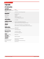
9.1 Technical Data
Technical Data
Measuring component:
Oxygen
Measuring range (specify when or-
dering):
0 … 25 Vol. %
Measuring principle: paramagnetic cell measuring principle
Measuring Data
Accuracy: 0.1 % O
2
absolute
Reproducibility: ± 0.05 % O
2
Response time: T
90
<10 s
Zero drift: ± 0.1 Vol.% O
2
per week
Sensitivity drift: ± 1% of measuring span per week
Gas inlet conditions
Gas temperature: +5 °C to 40 °C
Sample gas conditioning
Dew point: at least 5 °C below ambient temperature
Dust particles: Equipment filter with replaceable 8µ filter element
Calibration
Zero point: with nitrogen (technically pure), optionally with vacuum
Endpoint: with ambient air or test gas, depending on the measuring range
Climatic conditions
Ambient temperature: +10 °C to 45 °C
Transport and storage temperature: -25 °C to 65 °C
Relative humidity: <75 % annual average
Measurement output
Current signal: 4...20 mA (max. 400 Ω)
Voltage signal: 0...1 V ( min. 1 k Ω) optional
Displays
Measurement display: LCD 3½ digits
Power supply
Wall power supply: 100-240 V, 50/60 Hz
Construction
Housing: Aluminium housing with handle
Housing protection class: IP20 (standard)
Dimensions (h x w x d): 145 x 182 x 240 mm (standard housing)
Weight approx. 4.5 kg
16 Bühler Technologies GmbH BE550004 ◦ 07/2016-2

BA 4000 Inj.
9.2 Puncture devices
EV-1
Puncture device for single-hand operation. Suitable for sampling gas from soft packaging of modi-
fied atmosphere packed products.
EV-3
Puncture device with fixed needle. Suitable for sampling gas from soft packaging of modified atmo-
sphere packed products. The additional fine mesh filter also makes it suitable for sampling packages
with powdered products, e.g. coffee.
Water Stop fine mesh fil-
ter
For protecting the measuring cell when analysing moist gasses (bottles, tinned foods). Filters
particles, the special coating retains water liquids and aerosols.
Model EV-3
for soft packaging
Model EV-1
for soft packaging
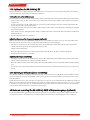
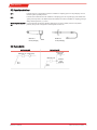
9.3 Flow charts
BA 4000 Inj. GV BA 4000 Inj. KV
Measuring cell Internal pump
EV-1
EV-3
Measuring cell
Vacuum pump
(external)
Solenoid
valve
(bleeding)
EV-1
EV-3
17Bühler Technologies GmbHBE550004 ◦ 07/2016-2

BA 4000 Inj.
10 Attached documents
– Declaration of Conformity KX550004
– RMA - Decontamination Statement
18 Bühler Technologies GmbH BE550004 ◦ 07/2016-2
Seite laden ...
Seite laden ...
Seite laden ...
-
 1
1
-
 2
2
-
 3
3
-
 4
4
-
 5
5
-
 6
6
-
 7
7
-
 8
8
-
 9
9
-
 10
10
-
 11
11
-
 12
12
-
 13
13
-
 14
14
-
 15
15
-
 16
16
-
 17
17
-
 18
18
-
 19
19
-
 20
20
-
 21
21
-
 22
22
-
 23
23


Buhler 55 11 399 Installation And Operation Instructions Manual
- Typ
- Installation And Operation Instructions Manual
- Dieses Handbuch ist auch geeignet für
in anderen Sprachen
- English: Buhler 55 11 399
Verwandte Papiere
-
Buhler FF-3-U-2 Installation And Operation Instructions Manual
-
-
-
-
Buhler GAS 222.31 Ex2 Installation And Operation Instructions Manual
-
-
-
-
-
Sonstige Unterlagen
-
GCE -PTALX Bedienungsanleitung
-
-
-
-
-
GCE Manifold Bedienungsanleitung
-
Phcbi MCO-170M Bedienungsanleitung
-
ITRON RB 4000 Benutzerhandbuch