ABB i-bus EIB Delta-Meter Installation And Operating Instructions Manual
- Kategorie
- Temperatur
- Typ
- Installation And Operating Instructions Manual

Montage- und Bedienungsanleitung
ABB i-bus
®
EIB
EIB Delta-Meter
Energieverbrauchszähler
Bed.Anl. Nr. GHQ 630 7061 P0002
Inhalt
Allgemeine Beschreibung .......... 2 Deutsch ........ 1
Technische Daten ...................... 3 English .......... 19
Montage ..................................... 7 Français ........ 37
EIB-Inbetriebnahme ................... 8 Hollandse ..... 55
LCD-Display ............................... 8 Italiano .......... 73
Programmiertasten ..................... 10 Español ........ 91
Software-Menü............................ 11 Svenska ....... 109
Installationsselbsttest und
Auslesen der Fehlercodes.......... 12
Netzüberwachungsfunktion und
Auslesen der el. Messgrößen..... 13
Fehlercodes ............................... 15
Anschlussbilder........................... 17
D
Druck Nr. G SK 09071 01 S4401
ABB STOTZ-KONTAKT GmbH
Eppelheimer Straße 82, D-69123 Heidelberg
Technische Hotline: 062 21/701-4 34
www.abb-stotz-kontakt.de
Die Angaben in dieser Druckschrift gelten vorbehaltlich
technischer Änderungen.

32
Technische Daten
Spezifikation Wandlerzähler Direktanschluss
Genauigkeitsklasse Klasse 1 und 2 nach IEC 1036/1268
Betriebsspannung siehe Bestellangaben (– 20% ... + 15%)
Nennstrom /1A oder /5A Wandler bis 65A
Frequenz (Bereich) 50 Hz (45 Hz ... 65Hz)
Temperaturbereich – 5° C ... + 45° C
Anschluss max. 10 mm
2
max. 25 mm
2
Schutzart IP20 nach EN 60 529
Gewicht 0,6 kg
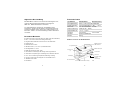
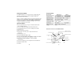
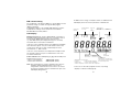
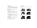
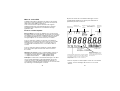
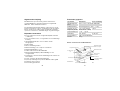
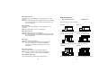
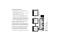
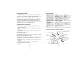
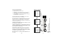
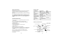
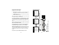
Funktionselemente der EIB Delta-Meter
Programmiertasten
EIB-Busanschluss,
LED und Taster
EIB-Anschlussplan
Geräteetikett
LCD-Display
LED
Anschlussklemmen
Klemmenbezeichnung
Plombierösen
(4)
Lichtsensor
Signalanschluss-
klemme
(nicht belegt)
Allgemeine Beschreibung
EIB Delta-Meter sind eine neue Generation PTB-zugelassener,
elektronischer Energieverbrauchszähler mit integrierter
ABB i-bus
®
EIB-Kommunikationsschnittstelle.
Sie sind platzsparend, zuverlässig, unempfindlich gegen
Störimpulse, geeignet für den Wechsel- und Drehstromeinsatz.
Als Zwischenzähler sind sie universell in Industrieanlagen, auf
Baustellen, in Büros, in Freizeiteinrichtungen und in Haushalten
einsetzbar.
Besondere Merkmale
● Präzise Erfassung des Energieverbrauchs (kWh, kvarh mit Kombizähler)
● Für 2, 3 und 4 Leiter-Stromnetze beliebiger Belastung
● Integrierte EIB-Schnittstelle zum Fernauslesen der Zählerdaten
● PTB-zugelassen
● Direktanschluss bis 65 A
● Wandleranschluss (/1 A oder /5 A) mit Wandlerzähler
● Genauigkeitsklasse 1 oder 2
● Erfüllt die Normen IEC 1036 / 1268
● Übersichtliches LCD-Display, LED Anzeige für Energieverbrauch
● Automatische Überprüfung der Verdrahtung mit „Installationsselbsttest“
● Stoss- und erschütterungsunempfindlich, Einbaulage: beliebig
● System pro M-Design: Aufschnappbar auf 35 mm DIN-Schiene
● Tarifzähler mit 4 Tarifen
● Plombierbar

54
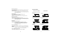
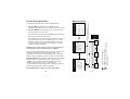
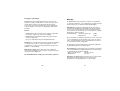
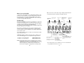
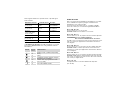
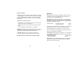
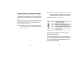
Beschriftung der EIB Delta-Meter (Beispiele)
Standard-Zähler
PTB-zugelassene Zähler
GH V784 0000 R0100
3 x 230/400 V~
50/60Hz
5(65) A Kl.2
ABB i-bus
®
EIB
1000 Imp/kWh
LED
SBE 21M000-200 2000 – 08 4600 55556
DZ 4000 W E
Typenbezeichnung
Symbol für Netz-
und Belastungsart
Nennstrom (Grenzstrom)
Genauigkeitsklasse
Kommunikations-
system
Nennfrequenz
Serien-Nr.Stromlaufplan
(DIN 43 856)
Nennspannung
LED-Frequenz
(Zählerkonstante)
Fertigungs-
datum
EIB-Konformitäts-
zeichen Ident-Nr.
V 1.08 042
GH V784 0100 R0101
3 x 230/400 V~
50 Hz
5 A Kl.2
ABB i-bus EIB
5000 Imp/kWh
LED
SAE 21M0001-200 2000 – 08 4610 55758
DZ 4010 W PE
20.15
98.80
Messwandlerzähler 5//1
Nennstrom
Genauigkeitsklasse
P = PTB-zugelassen
E = EIB-Schnittstelle
Zählerbezeichnung
PTB-Zulassungs-
zeichen
Schutzisolierungs- und
Schnittstellensymbole
V 1.08 042
®
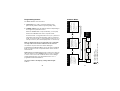
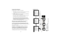
Geräte-Abmessungen (in mm)
Fronttüreinbausatz (nicht im Lieferumfang)

76
Montage
Die EIB Delta-Meter sind geeignet zum Einbau in Verteilern oder
Kleingehäusen, für Wandmontage oder Fronttüreinbau. Schnell-
befestigung auf Tragschienen 35 mm, nach DIN EN 50 022.
Anschluss: Der elektrische Anschluss erfolgt über Schraub-
klemmen. Die Klemmenbezeichnungen und Abisolierlängenhin-
weise sind im Anschlussbereich des Zählers eingeprägt.
Die Anschlussschrauben sind mit folgendem Drehmoment
anzuziehen.
Hauptanschluss: – Direktmessende Zähler 2,0 Nm
– Wandlerzähler 1,2 Nm
Beim Anschluss von Aluminiumleitern ist zu beachten, dass die
Kontaktflächen der Leiter gesäubert, gebürstet und mit Fett
behandelt werden. Die Anschlussklemmen sind nach ca. 6 bis
8 Wochen nachzuziehen.
Durch den Einsatz externer Klemmenblöcke beim Wandler-
anschluss können Servicemaßnahmen erleichtert werden.
Vorsicherung: Der Spannungspfad sollte durch einen vorge-
schalteten Sicherungsautomaten geschützt werden, um eine
Zerstörung des Zählers bei Kurzschluss und Überlast zu
verhindern.
– Direktmessende Zähler max. 65 A (63 A)
– Wandlerzähler max. 6 A
Plombierung: Um die EIB Delta-Meter nach Installation und
Programmierung vor unbefugten Eingriffen zu schützen, ist es
möglich, die Geräte an vier Ösen zu plombieren.
Wichtige Hinweise
EIB Delta-Meter sind ausschließlich zur Messung elektrischer
Energie vorgesehen. Einbau und Montage darf nur von
autorisierten Elektrofachkräften ausgeführt werden. Bei der
Planung und Errichtung von elektrischen Anlagen sind die
einschlägigen Normen, Richtlinien, Vorschriften und
Bestimmungen zu beachten.
Gefahrenhinweise:
– EIB Delta-Meter bei Transport, Lagerung und im Betrieb vor
Feuchtigkeit, Schmutz und Beschädigung schützen!
– EIB Delta-Meter nicht außerhalb der spezifizierten technischen
Daten betreiben!
– Es ist auf ausreichende Kühlung der EIB Delta-Meter zu
achten!
Reinigen: Verschmutzte Geräte können, sofern sie sich nicht
durch ein trockenes Tuch säubern lassen, durch ein mit
Seifenlösung leicht angefeuchtetes Tuch gereinigt werden.
Auf keinen Fall dürfen ätzende Mittel oder Lösungsmittel
verwendet werden.
Wartung: EIB Delta-Meter sind wartungsfrei. Bei Schäden
(z.B. durch Transport, Lagerung) dürfen keine Reparaturen
vorgenommen werden.
Beim Öffnen der EIB Delta-Meter erlischt der
Garantieanspruch!

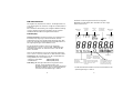
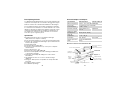
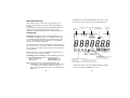
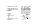
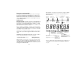
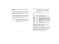
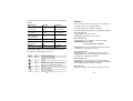
Spannungs-
anzeigen
L1 L2 L3 *
"Hand" leuchtet
(Tastendruck
wird erwartet)
Gerät OK
oder
ERROR
Wirkleistungs-
anzeige
Blindleistungs-
anzeige
Funktionsanzeige:
Pfeile rotieren mit konstanter
Geschwindigkeit, wenn der
Strom mind.
in einer Phase
über dem Anlaufstrom liegt.
Zähleinheit
Modusanzeige:
Kein Pfeil = Normal-Modus
Pfeil leuchtet = Alternativ-Modus
Pfeil blinkt = Instrument-Modus
Tarifanzeigen: (nur Tarifzähler)
Kein Symbol = Summe aller Tarife wird angezeigt.
TX blinkt allein = Tarif X ist aktiv und wird angezeigt.
TX blinkt, TY leuchtet = Tarif X ist aktiv, Tarif Y wird
angezeigt.
98
EIB-Inbetriebnahme
Die Vergabe der physikalischen Adresse, der Gruppenadressen,
sowie das Eingeben der Parameter erfolgt mit der ETS (EIB Tool
Software).
Eine ausführliche Beschreibung der verfügbaren EIB-Anwendungs-
software und deren Parametrierung finden Sie im „Benutzer
Handbuch EIB Delta-Meter Energieverbrauchszähler“.
LCD-Display
Angezeigte Energie: Die Energie wird mit einer Auflösung von
0.1 kWh (kvarh) angezeigt. Im ‘Alternativ-Modus’ wird der
Verbrauchswert mit einer zusätzlichen Dezimalstelle nach dem
Punkt, z.B. 0.01 kWh (kvarh) dargestellt. Bei Wandlerzählern ist
die angezeigte Energie ein Sekundärmesswert.
Bei den Kombinationszählern wechselt der angezeigte
Verbrauchswert ca. alle 6 s zwischen Wirk- und Blindenergie.
Anhand der Zähleinheit, d.h. kWh oder kvarh, ist die Art des
Wertes erkennbar.
Auch bei den Tarifzählern wechselt der angezeigte Verbrauchs-
wert ca. alle 6 s zwischen jedem der vier Tarife und der Summe.
Lastanzeigen: Die LCD-Anzeige ( [A], [R] ) und die LED-Last-
anzeige blinken mit einer Frequenz von:
– Direktmessende Zähler 1000 Imp/kWh(kvarh)
– Wandlerzähler 5000 Imp/kWh(kvarh)
Anmerkung: Die Energieverbrauchsmessung findet in allen
Anzeige- und Programmiermodes statt.
Bei Spannungsabfall oder Freischaltung der Geräte
bleibt der bis dahin gemessene Energieverbrauch,
trotz Erlöschen der LCD-Anzeige, erhalten.
Zusätzlich zu den Energieverbrauchswerten zeigt das
Multifunktions-LCD-Display dem Anwender die unten aufge-
führten Parameter an.
* Bei Dreileiter-Drehstromzählern leuchten im Normalfall nur die
Spannungsanzeigen L1 und L3.

10
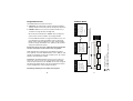
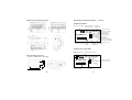
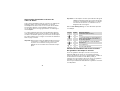
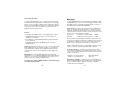
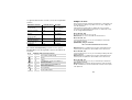
Software-Menü
Wirk-/Blindleistung
(L1,L2,L3,
Σ
)
Frequenz
Spannung (L1,L2,L3)
Strom (L1,L2,L3)
Cos
ϕ
(L1,L2,L3,Σ)
Instrument-Modus*
* Hinweis: Angezeigte Informationen und
Messgrößen sind abhängig vom Zählertyp.
Wirk-/Blindenergie (pro
Tarif) mit einer zusätzlichen
Dezimalstelle
Die Summe aller Tarife
Blindleistungs-LED
LCD-Segmenttest
Alternativ-Modus*
●
Wirk-/Blindenergie
Spannungsanzeige
Leistungsanzeige
Funktionsanzeige
OK/ Error - Symbol
Tarifanzeige
Normal-Modus*
LSc LSc
Menü-
Modus
3 Error End
Sc
Sc
4 InStr
Sc
S S
LSc
= ‘SET’-Taste drücken
= ‘SCROLL’-Taste drücken
= ‘SCROLL’-Taste > 3 Sekunden lang drücken
S
Sc
LSc
●
●
●
●
●
●
●
●
●
●
●
●
●
●
Errorcodes
●
Programmiertasten
Die EIB Delta-Meter besitzen zwei Tasten:
1. ‘SET’-Taste: Sie wird benutzt, um das Anzeigemenü [Menü-
Modus] und die Untermenüs [3 Error ] und [4 Instr ] aufzurufen.
2. ‘SCROLL’-Taste: Sie hat zwei verschiedene Funktionen, je
nachdem wie lange die Taste betätigt wird.
Mit einem kurzen Drücken der ‘SCROLL’-Taste springt man
zwischen den einzelnen Punkten im jeweiligen Modus.
Im ‘Normal-Modus’ bewirkt ein langer Tastendruck (>3 s) eine
Umschaltung in den ‘Alternativ-Modus’ und vom ‘Alternativ-
Modus’ in den ‘Instrument-Modus’. Bei allen anderen Modes
bewirkt ein langer Tastendruck einen „Abbruch“ (Die Software
springt eine Menüstufe zurück).
Es darf nur jeweils eine Taste gedrückt werden. Die Befehle
werden erst mit dem Loslassen der Taste ausgeführt.
Wird während der Programmierung zwei Minuten lang keine
Taste gedrückt, macht der EIB Delta-Meter einen „Abbruch“ und
springt eine Menüstufe zurück. Dies wiederholt sich, bis sich der
Zähler im ‘Normal-Modus’ befindet.
Lichtsensor: Die EIB Delta-Meter besitzen einen Lichtsensor.
Dieser hat, wenn er z.B. mit einer Taschenlampe angestrahlt
wird, dieselbe Funktion wie die ‘SCROLL’-Taste. Dies ermöglicht
die Abfrage der Zählerstände sowie der programmierten Werte
auch bei abgedeckten oder plombierten Geräten.
Einstellungsänderungen sind damit nicht möglich!
11

1312
Wichtig: Die nachfolgenden Beschreibungen zur Bedienung der
Software geben die Reihenfolge der zu drückenden
Tasten, ausgehend vom ‘Normal-Modus’, vor.
Die Beschreibungen sollten in Verbindung mit dem
Software-Menü Diagramm benutzt werden.
Im Menü-Modus [3 Error ] werden mögliche Fehlercodes
angezeigt.
Taste Anzahl Anzeige/Bemerkung
– – Normal-Modus (Ausgangszustand).
x 1 [3 Error ]
x 1 Fehlercodes werden automatisch angezeigt.
Wenn kein Fehler ansteht, wird der Text
[no Err] angezeigt.
x n
Tastet die einzelnen Fehlercodes manuell durch.
x 1 Zurück zu [3 Error ]
x 1 Zurück zum Normal-Modus.
Netzüberwachungsfunktion und
Auslesen der elektrischen Messgrößen
Alle elektrischen Messgrößen, die mit dem EIB Delta-Meter
gemessen werden um den Energieverbrauch zu erfassen,
können auf dem LCD-Display entweder im ‘Instrument-Modus’
oder im Menü-Modus [4 Instr ] angezeigt und für Netzüber-
wachungszwecke genutzt werden. Sämtliche elektrischen Mess-
größen sind Sekundärmesswerte. Je nach EIB Delta-Meter
stehen unterschiedliche Messgrößen zur Verfügung.
S
S
Sc
LSc
LSc
Installationsselbsttest und
Auslesen der Fehlercodes
Der Installationsselbsttest überprüft den Anschluss und die
Verdrahtung der EIB Delta-Meter. Der Installationsselbsttest wird
ca. alle 8 Sekunden automatisch durchgeführt. Sollten Geräte-
oder Installationsfehler auftreten, so werden sie auf der
LCD-Anzeige mit der Sammelmeldung „Error“ gemeldet.
Fehlercodes, die die Art der Geräte- oder Installationsfehler
beschreiben, können entweder im ‘Alternativ-Modus’ oder im
Menü-Modus [3 Error ] ausgelesen werden. Eine Beschreibung
der Fehlercodes und Hinweise bezüglich deren Beseitigung
finden Sie auf den folgenden Seiten.
Wichtig: Damit der EIB Delta-Meter den Installationsselbsttest
erfolgreich durchführen kann, muss der Zähler mit allen
Phasen angeschlossen sein und pro Phase ein Last-
strom von mindestens 100 mA sekundärseitig fließen.

1514
Fehlercodes
Nach der Durchführung eines Installationsselbsttests werden
mögliche Fehler im Menü-Modus [3 Error ], als Installations-
fehlercode angezeigt.
Eine ausführliche Beschreibung der Fehlercodes finden Sie im
„Benutzer Handbuch EIB Delta-Meter Energieverbrauchszähler“.
Error 100, 101, 102:
Phasenspannung (L1, L2, L3) ist nicht vorhanden.
Hinweis: Phasenspannung nicht angeschlossen.
Error 103, 107, 111:
Phasenspannung (L1, L2, L3) liegt über dem angegebenen
Maximalwert.
ACHTUNG! Beschädigungsgefahr!
Spannung sofort abschalten
Hinweise: Zähler hat falschen Nennspannungswert für diese
Anwendung. Falsche Spannungswandler.
Error 104, 108, 112:
Phasenspannung (L1, L2, L3) liegt unter dem angegebenen
Minimalwert.
Hinweise: Zähler hat falschen Nennspannungswert für diese
Anwendung. Falsche Spannungswandler.
Error 105, 109, 113:
Phasenstrom (L1, L2, L3) liegt über dem angegebenen
Maximalwert.
Hinweise: Übersetzungsverhältnis falsch eingestellt. Zähler hat
falschen Nennstromwert für diese Anwendung.
Error 115, 116:
Netzfrequenz liegt außerhalb des angegebenen Bereichs
(45 – 65 Hz).
S
Die folgende Tabelle beschreibt Format und Art der Messgröße.
Messgrößen Einheit Beispiel
Wirkleistung W P1 1250 W
L1, L2, L3, Σ kW P2 14.50 kW
Blindleistung
2
var P3 35 Var
L1, L2, L3, Σ kvar Pt 1.50 kVar
Spannung V U1 230.4 V
L1-N, L2-N, L3-N
(L1-L2, L2-L3)
1
Strom L1, L2, L3 A A3 22.93 a
Leistungsfaktor – Pf1 0.95
(L1, L2, L3)
2
, Σ
Frequenz Hz Fr 50.03
1
Bei Dreileiterzählern
2
Nur Kombinationszähler
Im Menü-Modus [4 InStr ] können je nach EIB Delta-Meter bis
zu 24 elektrische Installationsmessgrößen angezeigt werden.
Taste Anzahl Anzeige/Bemerkung
– – Normal-Modus (Ausgangszustand).
x 1 [3 Error ]
x 1 [4 InStr ]
x 1 Elektrische Messgrößen werden automatisch
angezeigt.
x n
Tastet die einzelnen Messgrößen manuell durch.
x 1 Zurück zu [4 InStr ]
x 1 Zurück zum Normal-Modus.
Sc
S
Sc
LSc
LSc

1716
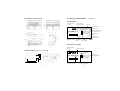
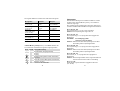
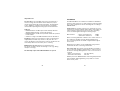
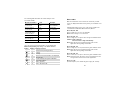
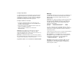
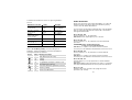
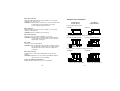
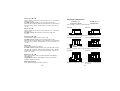
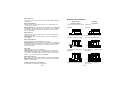
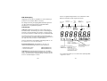
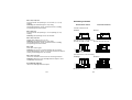
Anschlussbilder
Direktmessende Zähler Wandlerzähler
Zweileiter-Wechselstromnetz
DZ 2200 DZ 2210
L
N
3 111
L
N
2 3 111
Dreileiter-Drehstromnetz, beliebige Belastung
DZ 3100, DZ 3400, DZ 3500 DZ 3110, DZ 3410, DZ 3510
L1
L2
L3
3 4 6 7 91
L1
L2
L3
2 3 5 7 8 91
Vierleiter-Drehstromnetz, beliebige Belastung
DZ 4000/1 DZ 4010/1
L1
L2
L3
N
3 4 6 7 9 111
L1
L2
L3
N
2 3 4 5 6 7 8 9 111
Direktmessung bis 65 A Messung mit Stromwandlern
Error 118, 120, 122:
Phasenwinkel zwischen Phasenspannung L1 und Phasenstrom
(L1, L2, L3) falsch.
Hinweise: Stromanschlüsse verpolt. Stromdurchflussrichtung
durch Stromwandler falsch. Phasenspannungen nicht
korrekt angeschlossen.
Error 119, 121:
Phasenwinkel zwischen Phasenspannung L1 und
Phasenspannung (L2, L3) falsch.
Hinweis: Phasenspannungen nicht korrekt angeschlossen.
Error 123, 124, 125:
Negative Wirkleistung Phase (L1, L2, L3).
Hinweise: Stromanschlüsse verpolt. Stromdurchflussrichtung
durch Stromwandler falsch. Phasenspannungen nicht
korrekt angeschlossen.
Error 126:
Gesamte Wirkleistung negativ.
Hinweise: Ein oder mehrere Stromanschlüsse verpolt.
Stromdurchflussrichtung durch ein oder mehrere
Stromwandler falsch. Phasenspannungen nicht
korrekt angeschlossen.
Error 127, 128, 129:
Interne Fehler. Installationsselbsttest konnte nicht durchgeführt
werden.
Hinweise: Wiederholen Sie den Test. Bleibt die Fehlermeldung
bestehen, wenden Sie sich an ihren Händler.
Nicht erwähnte Fehlercodes:
Interne Fehler. Wenden Sie sich an ihren Händler.

19
Installation and operating instructions
ABB i-bus
®
EIB
EIB Delta-Meter
Electricity Meters
Instruction no.: GHQ 630 7061 P0002
Contents
General description . . . . . . . . . . 20 German . . . . . 1
Technical data . . . . . . . . . . . . . . 21 English . . . . . . 19
Installation . . . . . . . . . . . . . . . . . 25 French . . . . . . 37
EIB commissioning . . . . . . . . . . 26 Dutch . . . . . . . 55
LCD display . . . . . . . . . . . . . . . . 26 Italian . . . . . . . 73
Programming buttons . . . . . . . . . 28 Spanish . . . . . 91
Software menu . . . . . . . . . . . . . 29 Swedish . . . . . 109
Installation self-test
and reading out error codes . . . . 30
Network monitoring function
and reading out electrical
measured variables . . . . . . . . . . 31
Error codes . . . . . . . . . . . . . . . . 33
Wiring diagrams . . . . . . . . . . . . . 35
18

21
Technical data
Specification Transformer Direct
rated meter connected meter
Accuracy class Class 1 and 2 according to IEC 1036/1268
Operating voltage See selection table (– 20% … +15%)
Nominal current /1 A or /5 A transformer Up to 65 A
Frequency (range) 50 Hz (45 Hz … 65 Hz)
Temperature range – 5 °C … +45 °C
Connection max. 10 mm
2
max. 25 mm
2
Type of protection IP 20 according to EN 60 529
Weight 0.6 kg
Functional elements of the EIB Delta-Meter
Programming buttons
EIB bus connection
LED and push button
EIB wiring diagramm
Devive label
LCD display
LED
Connection terminals
Terminal markings
Sealing points
(4)
Light sensor
Signal terminal
(not used)
20
General description
The EIB Delta-Meters are a new generation of PTB-approved,
electronic, electricity meters with an integrated ABB i-bus
®
EIB communication interface.
They are compact, reliable, immune to interference impulses and
suitable for use in single phase and polyphase voltage networks.
They can be universally employed for submetering applications
in industrial installations, commercial buildings, offices, leisure
complexes and private households.
Special features
● Precise measurement of energy consumption (kWh, kvarh
with combination meter)
● For 2-, 3- and 4-wire voltage networks with any load
● Integrated EIB interface for remote reading of meter data
● PTB-approved
● Direct connection up to 65 A
● Transformer connection (/1A or /5 A) with transformer
rated meter
● Accuracy class 1 or 2
● Fulfils standards IEC 1036 / 1268
● Easy-to-read LCD display, LED display for energy consumption
● Automatic wiring check with an installation self-test
● Resistant to shocks and vibration, can be mounted
in any position
● System pro M design: can be snapped onto 35 mm DIN rail
● Tariff meter with 4 tariffs
● Sealable

23
Labelling of EIB Delta-Meters (Examples)
Standard meters
PTB-approved meters
GH V784 0000 R0100
3 x 230/400 V~
50/60Hz
5(65) A Kl.2
ABB i-bus EIB
1000 Imp/kWh
LED
SBE 21M000-200 2000 – 08 4600 55556
DZ 4000 W E
Type designation
Symbol for type of
network and load
Nominal current (limit current)
Accuracy class
Comminication
system
Nominal frequency
Serial no.Circuit diagram
(DIN 43 856)
Nominal voltage
LED frequency
(meter constant)
Date of
manufacture
EIB conformance
symbol
Identification no.
V 1.08 042
®
GH V784 0100 R0101
3 x 230/400 V~
50 Hz
5 A Kl.2
ABB i-bus EIB
5000 Imp/kWh
LED
SAE 21M0001-200 2000 – 08 4610 55758
DZ 4010 W PE
20.15
98.80
Messwandlerzähler 5//1
Nominal current
Accuracy class
P = PTB approved
E = EIB interface
Meter designation
PTB approval
symbol
Insulation and
interface symbol
V 1.08 042
®
22
Device dimensions (in mm)
Panel mounting kit (not included with delivery)

25
Installation
The EIB Delta-Meters are suitable for installation in distribution
boards or small enclosures, for wall mounting or panel mounting.
They can be snapped onto 35 mm mounting rails, according to
DIN EN 50 022.
Connection: The electrical connection is carried out via screw
terminals. The terminal markings and insulation strip lengths are
embossed in the terminal area of the meter. The connecting
screws should be tightened using the following torque:
Main terminal: – Direct connected meter 2.0 Nm
– Transformer rated meter 1.2 Nm
When connecting aluminium conductors, the contact surfaces of
the conductors should be cleaned, brushed and greased.
The connecting terminals should be re-tightened after approx.
6 to 8 weeks.
Maintenance procedures can be simplified by using external
terminal blocks when connecting a transformer.
Fuse protection: The voltage circuit should be protected by a
series-connected, miniature circuit-breaker, in order to prevent
the meter from being damaged in the event of a short circuit or
overload.
– Direct connected meter max. 65 A (63 A)
– Transformer rated meter max. 6 A
Seal: To protect the EIB Delta-Meter from being tampered with
after installation and programming, it is possible to seal the
device at four points.
24
Important notes
EIB Delta-Meters are intended solely for the measurement of
electrical energy. The installation and assembly may only be
carried out by authorised electrical specialists. The appropriate
norms, guidelines, regulations and specifications should be
observed when planning and setting up electrical installations.
Advisory:
– EIB Delta-Meters should be protected from damp, dirt and
damage during transport, storage and operation.
– EIB Delta-Meters should not be operated outside the specified
technical data.
– Sufficient cooling for the EIB Delta-Meter must be allowed for.
Cleaning: If devices become dirty, they can be cleaned using a
slightly damp cloth and soap solution if a dry cloth does not
remove the dirt. Corrosive materials or solutions should never be
used. Always disconnect the meter prior to cleaning.
Maintenance: EIB Delta-Meters are maintenance-free.
No repairs should be carried out if damage occurs (e.g. during
transport or storage).
The warranty expires if the EIB Delta-Meter is opened.

Voltage indicators
L1, L2, L3*
“Hand” lights up
(Push putton
action is expected)
Device OK
or
ERROR
Active power
indicator
Reactive
power indicator
Function indicator:
Arrows rotate at a constant speed,
if the current lies at least one phase
above the starting current
Unit of
measurement
Mode indicator:
No arrow = Normal mode
Arrow lights up = Alternative mode
Arrow flashes = Instrument mode
Tariff indicators: (only tariff meter)
No symbol = Total of all tariffs is displayed.
TX flashes alone = Tariff X is active and displayed.
TX flashes, TY lights up = Tariff X is active, tariff Y is displayed.
In addition to the energy consumption values, the multifunctional
LCD display shows the user the parameters outlined below.
* In the case of three-wire polyphase meters, only voltage
displays L1 and L3 normally light up.
2726
EIB commissioning
The assignment of the physical addresses, group addresses and
parameter settings is carried out using the ETS program
(EIB Tool Software).
A detailed description of the available EIB application software
and parameter settings can be found in the “User Manual
EIB Delta-Meter Electricity Meters”.
LCD display
Displayed energy: The energy is displayed with a resolution of
0.1 kWh (kvarh). In ‘Alternative mode’, the consumption value is
shown with an additional decimal place after the point,
e.g., 0.01 kWh (kvarh). The displayed energy is a secondary
measured value for transformer rated meters.
In the case of the combination meters, the displayed consumption
value alternates approx. every 6 seconds between active and
reactive power. The type of value is indicated by the unit of
measurement, i.e., kWh or kvarh.
In the case of the tariff meters, the displayed consumption value
also alternates approx. every 6 seconds between each of the
four tariffs and the total.
Power indicators: The LCD display ([A], [R]) and the LED power
indicator flash at a rate of:
– Direct connected meter 1000 Imp/kWh (kvarh)
– Transformer rated meter 5000 Imp/kWh (kvarh)
Note: The measurement of energy consumption takes place in
all display and programming modes. In the event of
voltage failure or disconnection of the device, the current
measured consumption value is maintained, in spite of the
LCD display being inactive.

29
Software-Menu
Active/reactive power
(L1, L2, L3, Σ)
Frequency
Voltage (L1, L2, L3)
Current (L1, L2, L3)
Cos ϕ (L1, L2, L3, Σ)
Instrument mode*
* Note: The measured variables displayed
are dependent on the meter type.
Active/reactive power
(per tariff) with an
additional decimal place
Total of all tariffs
Reactive power LED
LCD- segment test
Alternative mode*
●
Active/reactive power
Voltage display
Consumption display
Functional display
OK/ Error symbol
Tariff display
Normal mode*
LSc LSc
Menu
mode
3 Error End
Sc
Sc
4 InStr
Sc
S S
LSc
= Press ‘SET’ button
= Press ‘SCROLL’ button
= Press ‘SCROLL’ button > 3 seconds
S
Sc
LSc
●
●
●
●
●
●
●
●
●
●
●
●
●
●
Error codes
●
28
Programming buttons
The EIB Delta-Meter has two buttons:
1. ‘SET’ button: It is used to activate the display menu
[Menu mode] and the submenus [3 Error] and [4 Instr ].
2. ‘SCROLL’ button: It has two different functions depending on
the length of the push button action.
When the ‘SCROLL’ button is pressed briefly, you can jump
between the individual items in the respective mode.
In ‘Normal mode’, a long push button action (>3 s) switches to
‘Alternative mode’ and from ‘Alternative mode’ to ‘Instrument
mode’. In all other modes, a long push button action acts as a
“Escape” function. (The software jumps back one menu level).
Only one button may be pressed at a time. The commands
are only carried out once the button has been released.
If no buttons are pressed for two minutes during the
programming, the EIB Delta-Meter cancels the action and jumps
back one menu level. This is repeated until the meter returns to
‘Normal mode’.
Light sensor: The EIB Delta-Meters have a light sensor. This has
the same function as the ‘SCROLL’ button if a torch for example
is shone on the sensor. This enables both the meter readings
and programmed values to be queried both in the case of
programmed and installed devices.
It is not possible to modify any settings with the light
sensor.

31
Important: The following descriptions regarding the operation of
the software outline the sequence of push button
actions starting from ‘Normal mode’. The descriptions
should be used in connection with the software menu
diagram.
In Menu mode [3 Error ], the following error codes are
displayed.
Button Number Display/comment
– – Normal mode (starting position).
x 1 [3 Error ]
x 1 Error codes are displayed automatically.
If no error occurs, the text [no Err ] is
displayed.
x n Scrolls manually through the individual errors.
x 1 Back to [3 Error ]
x 1 Back to Normal mode.
Network monitoring function and reading out
the electrical measured variables
All electrical measured variables, which are measured with the
EIB Delta-Meter in order to record the energy consumption, can
be indicated on the LCD display either in ‘Instrument mode’ or in
Menu mode [4 Instr ] and used for network monitoring purposes.
All electrical measured variables are secondary measured values.
Different measured variables are available depending on the
EIB Delta-Meter.
S
S
Sc
LSc
LSc
30
Installation self-test and reading out error codes
The installation self-test checks the connection and wiring of
EIB Delta-Meters. The installation self-test is carried out
automatically approx. every 8 seconds. If device or installation
errors occur, they are reported on the LCD display with the
“Error” group signal.
Error codes which describe the type of device or installation
error can either be read out in ‘Alternative mode’ or Menu mode
[3 Error ]. A description of the error codes and notes on
remedying them can be found on the following pages.
Important: So that the EIB Delta-Meters can successfully carry
out the installation self-test, the meter must be
connected with all the phases and there must be a
load current of at least 100 mA per phase in the
secondary circuit.

33
Error codes
Once the installation self-test has been carried out, possible
errors are displayed in Menu mode [3 Error ] as installation error
codes.
A detailed description of the error codes can be found in the
“User Manual for EIB Delta-Meter Electricity Meters”.
Error 100, 101, 102:
Phase voltage (L1, L2, L3) is not available.
Note: Phase voltage is not connected.
Error 103, 107, 111:
Phase voltage (L1, L2 L3) lies above the given maximum value.
Caution: Risk of damage.
Disconnect the voltage immediately.
Note: Meter has the wrong nominal voltage value for this
application. Wrong voltage transformer.
Error 104, 108, 112:
Phase voltage (L1, L2, L3) lies below the given minimum value.
Note: Meter has the wrong nominal voltage value for this
application. Wrong voltage transformer.
Error 105, 109, 113:
Phase current (L1, L2, L3) lies above the given maximum value.
Note: Transformer ratio has been set incorrectly. Meter has the
wrong nominal current value for this application.
Error 115, 116:
System frequency lies outside the given range (45 – 65 Hz).
32
The following table describes the format and type of the
measured variable.
Measured variables Unit Example
Active power W P1 1250 W
L1, L2, L3, Σ kW P2 14.50 kW
Reactive power
2
var P3 35 VAr
L1, L2, L3, Σ kvar Pt 1.50 kVAr
Voltage V U1 230.4 V
L1-N, L2-N, L3-N
(L1-L2, L2-L3)1
Current L1, L2, L3 A A3 22.93 a
Power factor – Pf1 0.95
(L1, L2, L3)
2
, Σ
Frequency Hz Fr 50.03
1
For three-wire meters
2
Only combination meters
Up to 24 electrical measured variables can be displayed in
Menu mode [4 InStr ], depending on the EIB Delta-Meter.
Button Number Display/comment
– – Normal mode (starting position).
x 1 [3 Error ]
x 1 [4 InStr ]
x 1 Electrical measured variables are displayed
automatically.
x n Scrolls manually through the individual
measured variables.
x 1 Back to [4 InStr ]
x 1 Back to Normal mode.
Sc
S
Sc
LSc
LSc
S

35
Wiring diagrams
Direct connected meters Transformer rated meters
Single phase
DZ 2200 DZ 2210
L
N
3 111
L
N
2 3 111
3-phase without neutral
DZ 3100, DZ 3400, DZ 3500 DZ 3110, DZ 3410, DZ 3510
L1
L2
L3
3 4 6 7 91
L1
L2
L3
2 3 5 7 8 91
4-phase with neutral
DZ 4000/1 DZ 4010/1
L1
L2
L3
N
3 4 6 7 9 111
L1
L2
L3
N
2 3 4 5 6 7 8 9 111
Direct connection up to 65 A Connection with current
transformers
34
Error 118, 120, 122:
Incorrect phase angle between phase voltage L1 and phase
current (L1, L2, L3).
Note: Polarity of the current terminals has been reversed.
Direction of current flow in the current transformer is
incorrect. Phase voltages have been wrongly connected.
Error 119, 121:
Incorrect phase angle between phase voltage L1 and phase
current (L2, L3).
Note: Phase voltages have been wrongly connected.
Error 123, 124, 125:
Phase active power is negative (L1, L2, L3).
Note: Polarity of the current terminals has been reversed.
Direction of current flow in the current transformer is
incorrect. Phase voltages have been wrongly connected.
Error 126:
Total active power is negative.
Note: Polarity of one or several current terminals has been
reversed. Direction of current flow in one or several current
transformers is incorrect. Phase voltages have been
wrongly connected.
Error 127, 128, 129:
Internal error. Installation self-test could not be carried out.
Note: Repeat the test. If the error message remains, contact
your dealer.
Error codes that have not been mentioned:
Internal errors. Contact your dealer.

37
Instructions de montage et d'utilisation
ABB i-bus
®
EIB
Deltamètres EIB
Compteurs de consommation
d'énergie
N° réf. GHQ 630 7061 P0002
Table des matières
Description générale . . . . . . . . . 38 Deutsch . . . . . 1
Caractéristiques techniques . . . 39 English . . . . . 19
Montage . . . . . . . . . . . . . . . . . . 43 Français . . . . 37
Mise en service de l'EIB . . . . . . 44 Hollandse . . . 55
Écran à cristaux liquides . . . . . . 44 Italiano . . . . . 73
Touches de programmation . . . . 46 Español . . . . . 91
Menu du logiciel . . . . . . . . . . . . 47 Svenska . . . . 109
Autocontrôle d'installation et
lecture des codes de défauts . . 48
Fonction de surveillance du
réseau et lecture des grandeurs
électriques à mesurer . . . . . . . . 49
Codes de défauts . . . . . . . . . . . 51
Schémas des connexions . . . . . 53
36

39
Caractéristiques techniques
Spécification Transformateur Connexion directe
Classe de précision classe 1 ou 2 selon CEI 1036/1268
Tension de voir références à la commande
fonctionnement (– 20%...+15%)
Intensité nominale transformateur /1 A jusqu'à 65 A
ou /5 A
Fréquence (plage
de fréquence) 50 Hz (45 Hz...65 Hz)
Plage de
température – 5 °C...+45 °C
Connexion max. 10 mm
2
max. 25 mm
2
Type de protection IP 20 selon EN 60 529
Poids 0,6 kg
Éléments fonctionnels du deltamètre EIB
Touches de programmation
Borne de raccordement
au bus EIB
LED et bouton-poussoir
Schéma dews
connexions EIB
Désignation de
l'appareil
Écran à
cristaux
liquides
LED
Bornes de
connexion
Désignation des bornes
Cavaliers de
plombage (4)
Capteur lumineux
Borne de connexion
signal (sans fonction)
38
Description générale
Les deltamètres EIB appartiennent à une nouvelle génération de
compteurs électroniques de consommation d'énergie homologués
PTB avec interface de communication ABB i-bus
®
EIB intégrée.
Peu encombrants, fiables et insensibles aux impulsions parasites,
ils conviennent à une utilisation en courant alternatif et en courant
triphasé. Ils peuvent être employés de manière universelle comme
compteurs intermédiaires dans les installations industrielles, sur
les chantiers de construction, dans les bureaux, les centres de
loisirs ainsi que les logements privés.
Spécificités
● Enregistrement précis de la consommation d'énergie
(kWh, kvarh avec compteur combiné)
● Pour réseaux électriques à 2, 3 ou 4 fils de charge quelconque
● Interface de communication EIB intégrée pour le télérelevé des
données du compteur
● Homologation PTB
● Connexion directe jusqu'à 65 A
● Connexion pour transformateur (/1 ou /5 A) avec compteur-
transformateur
● Classe de précision 1 ou 2
● Respect des normes CEI 1036/1268
● Écran à cristaux liquides très lisible, affichage par LED de la
consommation d'énergie
● Vérification automatique du câblage avec “autocontrôle
d'installation”
● Insensibilité aux chocs et secousses; lieu de montage:
indifférent
● Design-pro M du système: enclipsable sur rails profilés DIN
de 35 mm
● Compteur tarifaire à 4 tarifs
● Possibilité de plombage
Seite wird geladen ...
Seite wird geladen ...
Seite wird geladen ...
Seite wird geladen ...
Seite wird geladen ...
Seite wird geladen ...
Seite wird geladen ...
Seite wird geladen ...
Seite wird geladen ...
Seite wird geladen ...
Seite wird geladen ...
Seite wird geladen ...
Seite wird geladen ...
Seite wird geladen ...
Seite wird geladen ...
Seite wird geladen ...
Seite wird geladen ...
Seite wird geladen ...
Seite wird geladen ...
Seite wird geladen ...
Seite wird geladen ...
Seite wird geladen ...
Seite wird geladen ...
Seite wird geladen ...
Seite wird geladen ...
Seite wird geladen ...
Seite wird geladen ...
Seite wird geladen ...
Seite wird geladen ...
Seite wird geladen ...
Seite wird geladen ...
Seite wird geladen ...
Seite wird geladen ...
Seite wird geladen ...
Seite wird geladen ...
Seite wird geladen ...
Seite wird geladen ...
Seite wird geladen ...
Seite wird geladen ...
Seite wird geladen ...
Seite wird geladen ...
Seite wird geladen ...
Seite wird geladen ...
Seite wird geladen ...
-
 1
1
-
 2
2
-
 3
3
-
 4
4
-
 5
5
-
 6
6
-
 7
7
-
 8
8
-
 9
9
-
 10
10
-
 11
11
-
 12
12
-
 13
13
-
 14
14
-
 15
15
-
 16
16
-
 17
17
-
 18
18
-
 19
19
-
 20
20
-
 21
21
-
 22
22
-
 23
23
-
 24
24
-
 25
25
-
 26
26
-
 27
27
-
 28
28
-
 29
29
-
 30
30
-
 31
31
-
 32
32
-
 33
33
-
 34
34
-
 35
35
-
 36
36
-
 37
37
-
 38
38
-
 39
39
-
 40
40
-
 41
41
-
 42
42
-
 43
43
-
 44
44
-
 45
45
-
 46
46
-
 47
47
-
 48
48
-
 49
49
-
 50
50
-
 51
51
-
 52
52
-
 53
53
-
 54
54
-
 55
55
-
 56
56
-
 57
57
-
 58
58
-
 59
59
-
 60
60
-
 61
61
-
 62
62
-
 63
63
-
 64
64


ABB i-bus EIB Delta-Meter Installation And Operating Instructions Manual
- Kategorie
- Temperatur
- Typ
- Installation And Operating Instructions Manual
in anderen Sprachen
- English: ABB i-bus EIB Delta-Meter
- français: ABB i-bus EIB Delta-Meter
- español: ABB i-bus EIB Delta-Meter
- italiano: ABB i-bus EIB Delta-Meter
- Nederlands: ABB i-bus EIB Delta-Meter
- svenska: ABB i-bus EIB Delta-Meter
Verwandte Artikel
Andere Dokumente
-
Baumer F 523 Installation and Operating Instructions
-
-
Gossen MetraWatt U389 Installationsanleitung
-
Mark G(N)CD Series Technical Manual
-
Hager TX 450 Benutzerhandbuch
-
Testo TE605-H1 Bedienungsanleitung
-
-
WAGO KNX IP Programmable Fieldbus Controller Benutzerhandbuch
-
SBC PG5 2.2/2.3 Benutzerhandbuch
-