
Technical manual
Technisches Handbuch
Livret technique
Technisch boek
Instrukcja techniczna
Manual tehnic
Teknisk vejledning
EN
DE
FR
NL
PL
RO
MARK GSX
0660150_R12
DK


3
Read this document before
installing the heater
If the manual refers to an image or table, a number will be shown between square brackets, for
example [3]. The number refers to images and tables at the back of the manual with the stated
number.
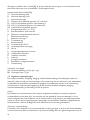
1.0 General
1.1 Application
The GSX appliance is designed for heating industrial and other non-domestic areas. The appliances
must be installed in a xed installation, preferably above the work oor, taking into account
minimum distances. Appliance type GSX is solely suitable for the free and direct intake of the air to
be heated and the free discharge of heated air into the room.
If areas are to be heated in which corrosive vapours are present (chlorinated hydrocarbons in
particular), which are either produced directly in the area, or which may be drawn in from the
outside by the heater via a duct or an open connection, wall air heaters cannot be used because of
the risk of corrosion to the heat exchanger.
Subject to change
The manufacturer is committed to constantly improving its products and reserves the right to make
changes in the specications without prior notice. The technical details are considered correct but
do not form the basis for a contract or warranty. All orders are accepted according to the standard
terms of our general sales and delivery conditions (available upon request). The information in this
document is subject to change without notice. The most recent version of this manual is always
available at www.markclimate.com/downloads.
1.2 Type indication
GSX
G Gas
S Axial fan
X Not condensating
Warning
Incorrect installation, adjustment, alteration, repair or maintenance work may lead to material
damage or injury. All work must be carried out by certied, qualied professionals. If the
appliance is not positioned in accordance with the instructions, the warranty shall be rendered
void. This appliance is not intended for use by children or persons with a physical, sensory or
mental handicap, or who lack the required experience or expertise, unless they are supervised
or have been instructed in the use of the appliance by somebody who is responsible for their
safety. Children must be supervised to ensure that they do not play with the appliance.
EN

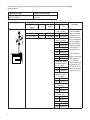
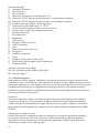
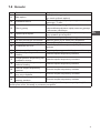
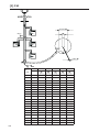
All the types of appliance are listed in table [3]. The various types are shown in the rows, and
technical information relating to the appliances is shown in the columns. See the key below.
Key to table [3]
A Nominal load (upper value)
B Nominal load (lower value)
C Nominal power
D Gas consumption for a specied gas type (15°) max/min
D1 CO
2
/O
2
for a specied gas type: max. load %
D2 CO
2
/O
2
for a specied gas type: min. load %
D3 Gas pre-pressure for a specied gas type
E Flue gas temperature (+/- 10°C)
G Burner fan start-max.-min.
H Diameter of the ue gas duct/air supply duct
I Electrical supply
J Electrical power
K Appliance fuse rating
L Protection class
M Air displacement (20°C)
N Air temperature rise
O Throw
P Ambient temperature min. /max.
Q Fan diameter(s)
R Fan speed
S Weight
T Flue gas mass
U Available ue pressure
V Gas connection
Information for Belgium
AA Nominal load (lower value) H gas / L gas
BB Power H gas / L gas
1.3 General warnings
Incorrect installation, adjustment, alteration, maintenance or repair may lead to material or
environmental damage and/or injuries. The appliance may therefore only be installed, adapted
or converted by a skilled and qualied installer, taking into account national and international
regulations. Faulty installation, adjustment, alteration, maintenance activity or repair shall render the
warranty void.
Appliance
When installing wall air heaters, you must comply with the relevant national and, if applicable,
regional and local regulations (e.g. gas company regulations, building regulations etc.). The wall
air heater may be installed only in an area and position suitable for the purpose, see Chapter 2
Installation. In Belgium, the wall air heater must be installed in accordance with Belgian standard
NBN D51-003.
Gas supply and connection
Before installation, check that the local distribution conditions, gas type and pressure and the
current adjustment of the appliance all match. An approved gas stop cock must be tted to the inner
pipeline.
4

5
Flue gas route
Combustion air supply pipelines and combustion gas exhaust ducts should have as few bends as
possible; in general, ow resistance should be kept to a minimum and in all cases, the diameter
should be constant along the entire length. The exhaust duct may not rest on the heater, but should
be suspended efciently! Follow the bracket instructions in chapter 10. If the ue gas exhaust duct
passes along or through combustible walls or oors, the duct must be sufciently far away from the
combustible material to prevent re.
1.4 Think of your safety
If you smell gas, you must not under any circumstances:
– Ignite an appliance
– Touch electrical switches or telephone from the area in question
Take the following action:
– Switch off the gas and electricity
– Activate the operational emergency plan
– Evacuate the building if necessary
2.0 Installation
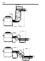
2.1 Positioning the appliance
After unpacking, check the appliance for damage. Check that the information relating to the type/
model and the electrical voltage is correct. Install the appliance and any accessories to a sufciently
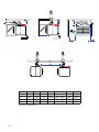
solid structure [2], taking into account the minimum free space required [1].
For GSX you should use the four M10-sized suspension points [21].
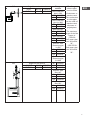
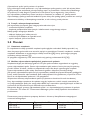
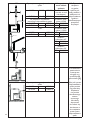
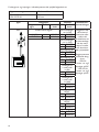
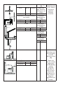
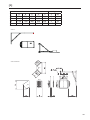
2.2 Positioningtheuegasexhaustsystemandairsupply
The device only has the CE approval in combination with its ue gas system. The ue gas system
includes: single ue set vertical or horizontal, extension pipes and elbows. Table [4] indicates
which parts can be used per appliance type. The ue gas system must be installed according to the
instructions attached.
If a ue gas set is to be installed sideways to or through a ammable oor or wall, then there must
be a minimum air gap of 25 mm around the ue gas sets. This to prevent re and / or scorch hazard.
The mentioned ue gas products are made of aluminum or stainless steel.
The combustion air inlet pipes may consist of the same materials as specied for the ue gas
discharge, but may also consist of materials mentioned in the table on pages 6-8. Other materials are
not allowed.
The maximum lenght of the ue gas system and combustion air inlet pipes is 6 meters and with 1x2
bends of 90°. Contact the manufacturer when exceeding the maximum discharge lenght.
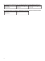
The roof and wall pass-throughs supplied by the manufacturer are identied by the following item
numbers:
Appliance type Roof pass-through C33 Wall pass-through C13
GSX 20/35
GSX 55/75/90
59 90 556
59 90 560
59 90 579
59 90 583
EN

6
The extension pipes and bends of the gas ue exhaust system must satisfy the following
requirements:
Appliance type Minimum diameter
GSX 20/35
GSX 55/75/90
80 mm
100 mm
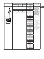
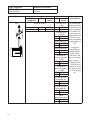
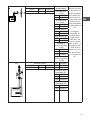
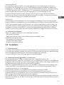
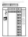
Type Flue gas exhaust Accessories Installation
remarks
Appliance
type
Ø Article
code
Ø Artikel-
nr.
B53 Single ue set vertical ALU Extension
pipe L=500
The ue gas
exhaust pipes
must be made
of aluminum or
stainless steel.
The combustion
air inlet pipes
can be made of
stainless steel,
aluminum or
polyethylene.
The maximum
length of the ue
gas system is:
- GSX 20:
5 meter pipe and
2 bends of 90°.
- GSX 35-90: 6
meter pipe and 2
bends of 90°.
20/35 5990556 80 5990727
55/75/90 5990560 100 5990728
ALU Extension
pipe L=1000
80 5990732
100 5990736
ALU Bend 45°
80 5990734
100 5990738
ALU Bend 90°
80 5990733
100 5990737
Stainless steel
Extension pipe
L=500
80 5990201
100 5990211
Stainless steel
Extension pipe
L=1000
80 5990202
100 5990212
Stainless steel
Bend 45°
80 5990204
100 5990214
Stainless steel
Bend 90°
80 5990203
100 5990213
Air inlet mesh
80 3002532
100 3002533

7
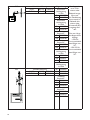
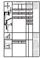
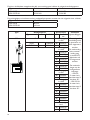
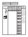
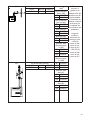
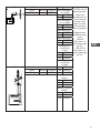
C13 Single ue set horizontal
20/35 80/125 5990579
55/75/90 100/150 5990583
Flue gas
exhaust
The ue gas
exhaust pipes
must be made
of aluminum or
stainless steel.
The combustion
air inlet pipes
can be made of
stainless steel,
aluminum or
polyethylene.
The maximum
length of the ue
system is:
- GSX 20:
2x5 meter pipe
and 2x2 bends
90°.
- GSX 35-90:
2x6 meter pipe
and 2x2 bends
90°.
ALU Extension
pipe L=500
80 5990727
100 5990728
ALU Extension
pipe L=1000
80 5990732
100 5990736
ALU Bend 45°
80 5990734
100 5990738
ALU Bend 90°
80 5990733
100 5990737
Stainless steel
Extension pipe
L=500
80 5990201
100 5990211
130 5990221
Stainless steel
Extension pipe
L=1000
C33 Single ue set vertical 80 5990202
20/35 80/125 5990556 100 5990212
55/75/90 100/150 5990560 130 5990222
Stainless steel
Bend 45°
80 5990204
100 5990214
130 5990224
Stainless steel
Bend 90°
80 5990203
100 5990213
130 5990223
EN

8
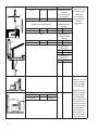
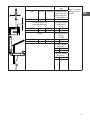
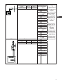
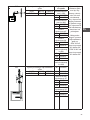
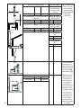
C53
Max. 3 m
Single ue set vertical Combustionair C53: The
condensate must
be discharged
efciently,
according to
the applicable
national
regulations.
20/35 80/125 5990556 Stainless steel
or ALU
Extension pipe
(see above)
55/75/90 100/150 5990560 OR
In combination with
single ue set horizontal
Polyethylene
Extension pipe
L=500
20/35 5990511 80 5989205
55/75/90 5990512 100 5989206
OR Polyethylene
Extension pipe
L=1000
20/35 0703100 80 5989210
55/75/90 0703101 100 5989211
Polyethylene
Bend 45°
80 5989224
100 5989233
Polyethylene
Bend 90°
80 5989225
100 5989236
C43 C43: Minimum
internal area of a
round common
drain pipe AV,
see table [5]
Applicable only
if the combined
ue gas system
has sufcient
natural draft: the
unit does not
have an internal
non-return valve.
Condensate is
not allowed to
ow back from
the ue system
into the unit.
C83 Single ue set horizontal
20/35 5990511
55/75/90 5990512

9
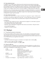
2.3 Gas connection
The installation of the gas pipeline and gas tap must comply with the relevant local and/or national
regulations. The gas tap must be positioned within reach of the appliance [3]. If the connection line is
subject to pressures above 60mbar, this gas tap must be closed. If there is any possibility of the presence
of dirt in the gas, use a gas lter. Always blow through the gas pipe in compliance with the regulations
prior to operating the appliance. If the appliance needs to be converted to a different type of gas than that
indicated on the type plate, the supplier of the appliance must be contacted. The supplier can advise you
which parts must be replaced in order to ensure correct operation of the appliance with the desired type
of gas. Conversion to a different type of gas is not permitted in Belgium.
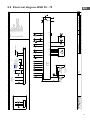
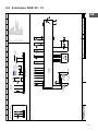
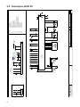
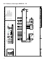
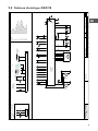
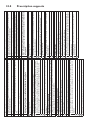
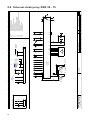
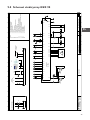
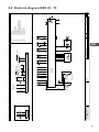
2.4 Electrical connection
Installation must comply with the relevant local and/or national regulations. Ensure that there is a correct
connection group with a mains fuse. The electrical diagram is displayed on the appliance. A basic diagram
for the GSX appliance can be found in chapter 8 and 9 Electrical diagram.
PLEASE NOTE:
– The appliance must be adequately earthed. The appliance must be tted with an isolator switch
which interrupts phase and zero (not earth).
– The isolator switch must be accessible at all times.
– Never, under any circumstances, allow the supply to the appliance to be interrupted by other
switches. This could result in the appliance overheating.
– The unit is phase sensitive.
3.0 Controls
3.1 Roomthermostatandresetbutton
The room thermostat must be located at a height of approx. 1.5m and not directly within the ow of
warm air. Connect the room thermostat using a shielded data cable in accordance with the wiring diagram
supplied for the appliance. Refer also to the technical information handbook supplied with the room
thermostat. Incorrect connection will render the manufacturer’s warranty void.
PLEASE NOTE:
– The maximum lengths and diameters are specied in the table [26].
– Earth the cable shielding to the appliance.
– For connecting multiple appliances, see [25] + [26].
3.2 Choiceofbuscable
Selection of the correct type of bus cable is based on the specic model for the country concerned. When
selecting the cable, the values noted in the technical details must be complied with. Bus cables of the
appropriate specications, which are offered in countries with an EIB market, are:
– YCYM Fixed system
EIB specication Dry, damp, wet rooms
In the open air (no direct exposure to sunlight)
Face-t, ush-t, in conduits
– J-Y(st)Y Fixed system
EIB specication Only in interior spaces
Face-t, in conduits
– JH(st)H Halogen-free conduits, remote system
– A-2Y(L)2Y or A-2YF(L)2Y Telephone ground cable, system in the outside area
EN

10
4.0 Start-up/shutdown
4.1 General
Before being packed, each appliance is fully tested for safety and correct operation. Among other
checks, the gas pressure and CO
2
are set. You must however always check the gas pre-pressure.
Never turn the adjusment screws without good cause. Do not forget to instruct the user on the
proper use and operation of the appliance and peripherals.
4.2 Checks
– Switch off the electricity supply at the main switch.
– Set the room thermostat to the minimum temperature.
– Open the gas stop cock, then carefully purge the gas pipes of air and check for leaks. Under no
circumstances use a naked ame! [27]
– Close the gas stop cock.
– In the case of the GSX, check whether the vanes in the air discharge port are set to the open
position (open to a min. of 45º).
– Switch on the electrical supply at the main switch and set the room thermostat to maximum
temperature. After the purge time has elapsed, the automatic ignition control will generate an
electric spark and the safety valve on the gas control unit will open. Because the gas stop clock is
closed, no ame will appear. The automatic ignition control will lock out after 4 attempts at
ignition, each lasting about 5 seconds. After waiting for approximately 30 seconds, the automatic
controller can be reset and the same cycle can be repeated.
– Open the gas stop cock, the appliance will now start up.
– Check the ame pattern at the main burner (clearly dened inner core, even combustion).
– In the case of appliances with an external fan, check that the maximum temperature increase of
30K is not exceeded.
4.3 Checkthattheroomthermostatisfunctioningcorrectly
If the setting is lower than the ambient temperature, the burner will extinguish. At a setting higher
than the ambient temperature, the burner should ignite.
4.4 Check the pre-pressure
The gas pre-pressure must be measured at the gas unit when the appliance is in operation. The pre-
pressure is indicated on the appliance’s type plate. To check, the volume of gas consumed [3] can be
measured via the gas meter (temporarily switch off all other appliances that consume gas).
4.5 Check appliance operation.
Finally, check that the operation of the appliance cannot be inuenced by other appliances close to
it, localised air ows or corrosive or explosive vapours, etc.
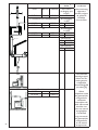
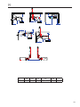
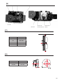
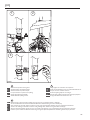
4.6 Set the gas control unit [6]
Before being packed, each appliance is fully tested for safety and correct operation. The correct
combustion values are set during this procedure. If checks indicate that the CO
2
value is different
from that in table [3], adjustments may be made (difference of more than 0.2%). Never adjust set
screws without the correct measuring equipment.

11
Legend [6]
1 Measuring point for gas pre-pressure
2 Measuring point for offset
3 Offset adjustment screw
4 Throttle adjustment screw
Step 1
Set the appliance to run at full operational load by pressing and holding the reset button of the unit
for at least 5 seconds. The fault lamp in the reset button ashes at a high frequency. If the appliance
will not re up, you can try sealing the air opening in the gas mixer during ignition using your thumb
and index nger. This makes the mixture richer and easier to ignite. Check the CO
2
when the
appliance is operating at high output. If the CO
2
is too high, turn the throttle adjuster to the right
(less gas). If the CO
2
is too low, turn the screw to the left (more gas). The correct CO
2
value is
shown in table [3] (D1).
Step 2
Set the appliance to minimum load by shortly pressing the reset button of the unit. The fault lamp
in the reset button ashes at a low frequency. Check the CO
2
against the value in table [3] (D2). If
different, correct by turning the offset adjuster under the cap. To the left for lower CO
2
, to the right
for higher CO
2
.
After setting the gas control unit press the reset button again (the light goes out).
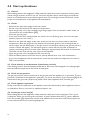
4.7 Shutting down the heater
For short periods of time:
– Set the room thermostat to the minimum temperature.
– Do not switch off the electricity supply at the main switch as this may damage the maximum
temperature and safety thermostat.
For longer periods of time:
– Set the room thermostat to the minimum temperature.
– After ± 5 minutes, the electrical power may be switched off.
5.0 Maintenance
5.1 General
The appliance must be subjected to maintenance at least once a year, more often if necessary. If
applicable, ask a qualied installer for maintenance advice. Maintenance may only be carried out by
qualied maintenance technicians. When carrying out maintenance, the appliance must have been
shut down for an extended period. Make sure that you comply with all safety rules.
5.2 Cleaning
All gas-red appliances require periodical maintenance. This maintenance work must be performed
by qualied maintenance technicians.
– Before starting maintenance work, the gas and electrical supplies must be shut off. See also
paragraph 4.7
– Check all gaskets and replace if required.
– The gas transport section is located on the side of the appliance in the electrical compartment.
The gas transport section can be removed from the appliance as a single assembly. To do so, six
M6 nuts must be removed and the electrical wiring disconnected.
EN

12
– Removal of the gas transport section provides access to the burner and the ignition/ionisation
electrode. It is recommended to replace the ignition/ionisation electrode yearly during regular
maintenance.
– Check the burner surface for irregularities. Never use a steel brush!
– Clean the gas mixer using a soft brush. Make sure that no dust gets into the burner and the gas
suction tube. Ret the gas transport section, reconnect the wiring and the gas and electrical
supplies. [27]
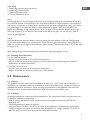
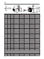
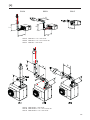
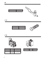
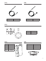
6.0 Description of parts
The parts are:
– Fan [7]
– Combustion air fan [8]
– Ignition set [9]
– Burner [11]
– Gas control unit [12]
– Ambient temperature sensor [13]
– Outlet temperature sensor / max [14]
– Gasket set [15]
– Microprocessor [16]
– Gas mixer [17]
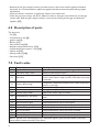
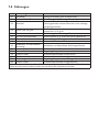
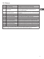
7.0 Fault codes
Code Error Description
01 Ignition failure Ignition has failed (three attempts at ignition).
02 Gas valve relay/T max. Maximum thermostat is open
03 Gas valve
Gas valve faulty / Wire connecting the gas valve to the
burner control box is open-circuit or has been incorrectly
connected.
10 Sensor diff too high
Temperature difference between both outlet temperature
sensors is too high.
25 T max. Maximum thermostat is open
31 Too many attempts to restart Flame goes out (3x) when the device is in operation.
42 Choke relay broken Relay of the choke valve is broken
43 Combustion air fan failure
The current speed of the combustion air fan deviates too
much
65 Phase and zero back to front Phase and zero not connected correctly
72 Air out sensor open Outlet temperature sensor interrupted
73 Unit temp sensor open Ambient temperature sensor interrupted
78 Air out safety open Outlet temperature sensor interrupted
80 Air out shorted Outlet temperature sensor has short circuited
81 Unit temp shorted Ambient temperature sensor has short circuited
86 Air out safety shorted Outlet temperature sensor has short circuited
When a different error code displayed on the thermostat appears, press the Reset button. If the fault
returns, please contact the vendor of the device.

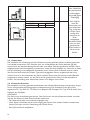
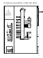
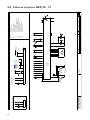
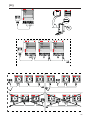
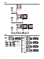
8.0 Electrical diagram GSX 20 - 75
EN
13

14
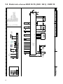
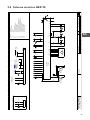
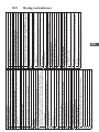
9.0 Electrical diagram GSX 90

15
EN
10.0 Bracket instructions
[20] Basic instructions
Single-wall steel ue system
These basic requirements are only applicable to connecting pipes with the following
characteristics:
• Connection to a heater with built-in ventilator.
• Connection in the installation area of the appliance and in sight.
• Single-walled, rigid aluminium or stainless steel pipes with CE certication (cf EN
1856-1/2, P1, W).
• Maximum ue gas temperature of 160ºC.
• Diameters from Ø80 to Ø130 mm.
Caution! This checklist includes some basic instructions. For further
instructions for this unit paragraph 2.2.
Checklist
General
We recommend using the brackets of manufacturer Cox Geelen.
Do not combine components of various materials or nished products for the
connecting pipe, except where the manufacturer of the system allows this. Exception
to this rule: components tested according to Gastec Qa KE83-3 (thick-walled
aluminium) and 5 (stainless steel).
The minimum insertion length of sleeves and spigot ends is 40mm.
Mount tension free.
Create a slope 3 degrees (so 50mm per meter) to the unit for a proper drainage of
the condensate.
Connecting and bracing
Brace every corner to or close to the sleeve. Exception when connecting to the unit:
- If the connecting pipe is shorter than 0.25m before and after the rst ben, the
bracket at the rst bend can be omitted.
- Place the rst bracket on a maximum of 0.5m pipe length from the unit.
Horizontal and non-vertical pipes
- Maximum bracket distance of 1m.
- Divide lengths between brackets evenly.
Vertical pipes
- Maximum bracket distance of 2m.
- Divide lengths between brackets evenly.
Gaskets and seals
Avoid damaging of the sealing rings by cutting of in an angle and deburring.
When using tension-proof connections follow the instructions of the manufacturer.
Do not screw or park connections.
It is not allowed to seal foam or paste (for example PUR, silicone, etc.).
If necessary lubricate sealing rings exclusively with max. 1% soap solution or water.
Caution! Do not use grease, Vaseline, petroleum jelly or oil.
Air supply system
These basic instructions are only applicable to air supply pipes with the following
characteristics:
• Connection to a closed heater with built-in fan.
• Connection in the installation area of the appliance and in sight.
• Aluminium, stainless steel or plastic air supply pipes.
• Diameter air supply pipe of Ø80 to Ø130 mm.
Caution! This checklist includes some basic instructions. For further
instructions for this unit paragraph 2.2.
Checklist
General
Do not combine components of various materials or nished products for the
connecting pipe.
The minimum insertion length of sleeves and spigot ends is 40mm.
When using plastic air supply pipes make sure that the distance to the ue pipe is at
least 35mm.
Mount tension free.
Connecting and bracing
Place the rst bracket on a maximum of 0.5m pipe length from the unit.
Horizontal and non-vertical pipes
- Maximum bracket distance of 1m.
- Divide lengths between brackets evenly.
Vertical pipes
- Maxium bracket distance of 2m.
- Divide lengths between brackets evenly.
Gaskets and seals
Avoid damaging of the sealing rings by cutting of in an angle and deburring.
Seals of metal air supply pipes may be bolted or parked. This is not allowed for plastic
air supply pipes.
Guarantee the gas-thightness by using components that are provided with a seal.
If necessary lubricate sealing rings exclusively with max. 1% soap solution or water.
Caution! Do not use grease, Vaseline, petroleum jelly or oil.


17
DE
Lesen Sie dieses Dokument sorgfältig
durch, bevor Sie das Gerät installieren
Wenn in der Anleitung auf eine Abbildung oder Tabelle verwiesen wird, wird eine Zahl in eckigen
Klammern angegeben, beispielsweise [3]. Die Zahl verweist auf die Abbildungen und Tabellen mit
der entsprechenden Nummer am Ende der Anleitung.
1.0 Allgemeines
1.1 Einsatzbereich
Der GSX ist für die Beheizung von industriellen und anderen Nicht -Wohngebäuden konzipiert.
Die Geräte müssen in einer festen Anordnung, vorzugsweise oberhalb der Arbeitsäche, und unter
Berücksichtigung von Mindestabständen installiert werden. Das Gerät GSX eignet sich ausschließlich
zum freien und direkten Ansaugen der zu erwärmenden Luft und zum freien ausblasen der
erwärmten Luft in den Raum.
Zum Heizen von Räumen, in denen korrosive Dämpfe vorhanden sind (insbesondere chlorierte
Kohlenwasserstoffe), die entweder direkt aus dem Raum oder über einen Anschluss oder eine
offene Verbindung von außen durch den Warmlufterzeuger angesaugt werden können, können diese
aufgrund der Korrosionsgefahr für den Wärmetauscher nicht eingesetzt werden.
Änderungen vorbehalten
Der Hersteller strebt eine kontinuierliche Verbesserung der Produkte an und behält sich das
Recht vor, ohne vorherige Mitteilung Änderungen an den technischen Daten vorzunehmen. Die
technischen Angaben werden als korrekt angenommen, bilden aber keine Grundlage für einen
Vertrag oder Gewährleistungsansprüche. Alle Bestellungen werden gemäß den Standardkonditionen
in unseren AGB‘s (auf Anfrage erhältlich) angenommen. Die Informationen in diesem Dokumente
können sich ohne vorherige Ankündigung ändern. Die neuste Version dieses Handbuches nden Sie
immer auf unserer Interseite unter www.mark.de/downloads.
1.2 Typenkennzeichnung
GSX
G Gas
S Axialventilator
X nicht kondensierend
Warnhinweis
Fehlerhaft durchgeführte Installationen, Einstellungen, Änderungen, Reparaturen oder
Wartungsmaßnahmen können zu Sachschäden und Verletzungen führen. Alle Arbeiten
müssen von geprüften, qualizierten Fachleuten durchgeführt werden. Falls das Gerät nicht
vorschriftsgemäß aufgestellt wird, erlischt die Garantie.
Dieses Gerät ist nicht für den Gebrauch durch Personen (einschließlich Kindern) mit
verminderter körperlicher, Sinnes- oder geistiger Leistungsfähigkeit oder mangelnder
Erfahrung und mangelnden Kenntnissen bestimmt, sofern sie nicht unter Aufsicht stehen
oder durch eine Person, die für ihre Sicherheit verantwortlich ist, im Gebrauch des Geräts
angeleitet werden. Kinder müssen vom Gerät ferngehalten werden.

18
Alle Gerätetypen sind in Tabelle [3] aufgeführt. In den Zeilen sind die verschiedenen Typen
aufgeführt, in den Spalten die technischen Angaben zu den Geräten. Siehe die folgende Legende.
Legende zu Tabelle [3] (Seite 92)
A Nennbelastung (oberer Wert/Brennwert)
B Nennbelastung (unterer Wert/Heizwert)
C Nennleistung
D Gasverbrauch bei bestimmten Gasarten (15°C) max./min.
G25 - L-Gas
G20 - H-Gas
D1 CO
2
/O
2
bei bestimmten Gasarten: max. Belastung %
D2 CO
2
/O
2
bei bestimmten Gasarten: min. Belastung %
D3 Gasießdruck bei bestimmten Gasarten
E Abgastemperatur (+/- 10°C)
G Drehzahl Brennerventilator Start-max-min
H Durchmesser Abgassystem/Luftzufuhr
I Einspeisung
J Elektrische Leistung
K Absicherung
L Schutzklasse
M Luftleistung (20 °C)
N Lufttemperaturerhöhung
O Wurfweite
P Umgebungstemperatur min. /max
Q Lüfterdurchmesser
R Lüfterdrehzahl
S Gewicht
T Abgasmassenstrom
U Förderdruck
V Gasanschluss
Informationen für Belgien
AA Nennbelastung (unterer Wert/Heizwert) H Gas / L Gas
BB Leistung H Gas / L Gas
1.3 AllgemeineWarnhinweise
Eine unsachgemäß ausgeführte Installation, Feinabstimmung, Änderung, Inspektion oder
Instandsetzung kann zu Materialschäden, Umweltschäden und/oder Verletzungen führen. Lassen
Sie das Gerät daher nur von fachkundigen und qualizierten Installateuren unter Berücksichtigung
der nationalen und internationalen Vorschriften installieren, anpassen oder umbauen. Im Falle
einer unsachgemäßen Installation, Einstellung, Änderung, Wartung oder Instandsetzung erlischt die
Gewährleistung.
Gerät
Bei der Installation von wandmontierten Lufterhitzern sind die geltenden nationalen und ggf.
regionalen und lokalen Vorschriften (z.B. Vorschriften des Gasunternehmens, Bauverordnungen,
usw.) zu beachten. Die Installation des Warmlufterzeuger darf ausschließlich in hierfür geeigneten
Räumen und an einem hierfür geeigneten Ort erfolgen; siehe Kapitel 2, Installation. In Belgien ist der
Lufterhitzer gemäß der belgischen Norm NBN D51-003:2010+A1:2014 zu installieren.

19
DE
Gaszufuhr und Gasanschluss
Überprüfen Sie vor der Installation, ob die lokalen Versorgungsbedingungen, Gasart und -druck und
die aktuelle Einstellung des Geräts miteinander übereinstimmen. An der Innenleitung ist ein geprüfter
Gasabsperrhahn anzubringen.
Abgasstrecke
Zuluftleitungen und Abgasleitungen sollten möglichst wenig Krümmungen aufweisen; grundsätzlich
muss der Widerstand auf ein Minimum beschränkt und in jedem Fall derselbe Durchmesser über die
gesamte Strecke eingehalten werden. Die Ableitung darf nicht auf dem Warmlufterzeuger abgestützt
werden, sondern muss in zweckmäßiger Weise aufgehängt werden (beachten Sie bitte die Anweisung
aus Kapital 10.) Wenn die Abgasableitung durch brennbare Wände oder Böden oder an ihnen
entlang geführt wird, muss die Leitung zur Vermeidung von Bränden einen ausreichenden Abstand
haben.
1.4 Denken Sie an Ihre Sicherheit
Wenn Sie Gasgeruch wahrnehmen, ist es ausdrücklich verboten:
– ein Gerät zu zünden
– elektrische Schalter zu berühren oder in demselben Raum zu telefonieren
Ergreifen Sie die folgenden Maßnahmen:
– Gaszufuhr und Strom abschalten
– Betriebsnotfallplan aktivieren
– Ggf. das Gebäude evakuieren
2.0 Installation
2.1 Aufstellung des Geräts
Überprüfen Sie das Gerät nach dem Auspacken auf Beschädigung. Überprüfen Sie die Richtigkeit
des gelieferten Typs/Models sowie die elektrische Spannung. Montieren Sie das Gerät und etwaige
Zubehörteile an eine ausreichend stabile Konstruktion [2] unter Berücksichtigung der erforderlichen
Mindestabstände [1].
Verwenden Sie für den GSX (Gerät mit Axialventilator) die vier M10 Aufhängepunkte [21].
2.2 AnbringenderAbgasableitungundderLuftzufuhr
Das Gerät hat nur eine CE-Zulassung in Kombination mit dem von MARK gelieferten Abgassystem,
mit Ausnahme des Abgassystems vom Typ C43/C83.
Das Abgassystem umfasst: Dach- und Wanddurchführung, Verlängerungen und Bögen. Aus der
Tabelle [4] können Sie entnehmen, welche Anbauteile für welchen Gerätetyp verwendet werden
können. Das Abgassystem muss entsprechend der beiliegenden Anleitung installiert werden.
Zur Vermeidung von Bränden, müssen Abgasleitungen entlang oder durch brennbare Wände oder
Böden mit einem Mindestabstand von 25 mm verlegt werden.
Die genannten Produkte zur Rauchgasabfuhr bestehen aus Aluminium und Edelstahl.
Die Zuluftleitungen können aus gleichem Material bestehen, wenn sie für Abgas zugelassen sind,
oder aus Materialien, die in der Tabelle auf Seite 20-23 aufgeführt sind. Andere Materialien sind nicht
zugelassen.
Die max. Länge des Abgasrohres und der Verbrennungsluftzufuhrleitung beträgt 6m, zusätzlich 1x2
Bögen von 90˚. Kontaktieren Sie den Hersteller, wenn Sie die maximale Länge überschreiten.
Anordnung und Anzahl der Revisionsöffnungen nach DIN 18160.

20
Die vom Hersteller mitgelieferten Dach- und Wanddurchführungen haben folgende Artikelnummer:
Gerätetyp Dachdurchführung C33 Wanddurchführung C13
GSX 20/35
GSX 55/75/90
59 90 556
59 90 560
59 90 579
59 90 583
Die Verlängerungsrohre und -bögen des Abgassystems müssen die folgenden Anforderungen erfüllen:
Gerätetyp Mindestdurchmesser
GSX 20/35
GSX 55/75/90
80 mm
100 mm
Seite wird geladen ...
Seite wird geladen ...
Seite wird geladen ...
Seite wird geladen ...
Seite wird geladen ...
Seite wird geladen ...
Seite wird geladen ...
Seite wird geladen ...
Seite wird geladen ...
Seite wird geladen ...
Seite wird geladen ...
Seite wird geladen ...
Seite wird geladen ...
Seite wird geladen ...
Seite wird geladen ...
Seite wird geladen ...
Seite wird geladen ...
Seite wird geladen ...
Seite wird geladen ...
Seite wird geladen ...
Seite wird geladen ...
Seite wird geladen ...
Seite wird geladen ...
Seite wird geladen ...
Seite wird geladen ...
Seite wird geladen ...
Seite wird geladen ...
Seite wird geladen ...
Seite wird geladen ...
Seite wird geladen ...
Seite wird geladen ...
Seite wird geladen ...
Seite wird geladen ...
Seite wird geladen ...
Seite wird geladen ...
Seite wird geladen ...
Seite wird geladen ...
Seite wird geladen ...
Seite wird geladen ...
Seite wird geladen ...
Seite wird geladen ...
Seite wird geladen ...
Seite wird geladen ...
Seite wird geladen ...
Seite wird geladen ...
Seite wird geladen ...
Seite wird geladen ...
Seite wird geladen ...
Seite wird geladen ...
Seite wird geladen ...
Seite wird geladen ...
Seite wird geladen ...
Seite wird geladen ...
Seite wird geladen ...
Seite wird geladen ...
Seite wird geladen ...
Seite wird geladen ...
Seite wird geladen ...
Seite wird geladen ...
Seite wird geladen ...
Seite wird geladen ...
Seite wird geladen ...
Seite wird geladen ...
Seite wird geladen ...
Seite wird geladen ...
Seite wird geladen ...
Seite wird geladen ...
Seite wird geladen ...
Seite wird geladen ...
Seite wird geladen ...
Seite wird geladen ...
Seite wird geladen ...
Seite wird geladen ...
Seite wird geladen ...
Seite wird geladen ...
Seite wird geladen ...
Seite wird geladen ...
Seite wird geladen ...
Seite wird geladen ...
Seite wird geladen ...
Seite wird geladen ...
Seite wird geladen ...
Seite wird geladen ...
Seite wird geladen ...
Seite wird geladen ...
Seite wird geladen ...
Seite wird geladen ...
Seite wird geladen ...
Seite wird geladen ...
Seite wird geladen ...
Seite wird geladen ...
Seite wird geladen ...
Seite wird geladen ...
Seite wird geladen ...
Seite wird geladen ...
Seite wird geladen ...
-
 1
1
-
 2
2
-
 3
3
-
 4
4
-
 5
5
-
 6
6
-
 7
7
-
 8
8
-
 9
9
-
 10
10
-
 11
11
-
 12
12
-
 13
13
-
 14
14
-
 15
15
-
 16
16
-
 17
17
-
 18
18
-
 19
19
-
 20
20
-
 21
21
-
 22
22
-
 23
23
-
 24
24
-
 25
25
-
 26
26
-
 27
27
-
 28
28
-
 29
29
-
 30
30
-
 31
31
-
 32
32
-
 33
33
-
 34
34
-
 35
35
-
 36
36
-
 37
37
-
 38
38
-
 39
39
-
 40
40
-
 41
41
-
 42
42
-
 43
43
-
 44
44
-
 45
45
-
 46
46
-
 47
47
-
 48
48
-
 49
49
-
 50
50
-
 51
51
-
 52
52
-
 53
53
-
 54
54
-
 55
55
-
 56
56
-
 57
57
-
 58
58
-
 59
59
-
 60
60
-
 61
61
-
 62
62
-
 63
63
-
 64
64
-
 65
65
-
 66
66
-
 67
67
-
 68
68
-
 69
69
-
 70
70
-
 71
71
-
 72
72
-
 73
73
-
 74
74
-
 75
75
-
 76
76
-
 77
77
-
 78
78
-
 79
79
-
 80
80
-
 81
81
-
 82
82
-
 83
83
-
 84
84
-
 85
85
-
 86
86
-
 87
87
-
 88
88
-
 89
89
-
 90
90
-
 91
91
-
 92
92
-
 93
93
-
 94
94
-
 95
95
-
 96
96
-
 97
97
-
 98
98
-
 99
99
-
 100
100
-
 101
101
-
 102
102
-
 103
103
-
 104
104
-
 105
105
-
 106
106
-
 107
107
-
 108
108
-
 109
109
-
 110
110
-
 111
111
-
 112
112
-
 113
113
-
 114
114
-
 115
115
-
 116
116


Mark GSX Series Technical Manual
- Kategorie
- Kamine
- Typ
- Technical Manual
in anderen Sprachen
- English: Mark GSX Series
- français: Mark GSX Series
- Nederlands: Mark GSX Series
- dansk: Mark GSX Series
- polski: Mark GSX Series
- română: Mark GSX Series
Verwandte Artikel
-
Mark SHOPHEATER Technical Manual
-
-
-
-
-
-
-
-
Andere Dokumente
-
Baxi Power HT Series Installation, Operation and Maintenance Manual
-
ACV Delta G25 BF (1999) Technical Manual
-
-
Bosch DWB063451/03 Bedienungsanleitung
-
Dovre S203.212 Bedienungsanleitung
-
La Nordica TERMOSUPREMA COMPACT DSA Instructions For Installation, Use And Maintenance Manual
-
ABB i-bus EIB Delta-Meter Installation And Operating Instructions Manual
-
Honeywell 50032072GSX Series Explosion Proof Safety Switch (Multiple Languages) Installationsanleitung
-
Bauknecht GSX 6993 Installationsanleitung