
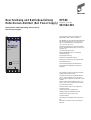
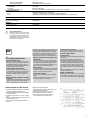
Beschreibung und Betriebsanleitung
Hutschienen-Netzteil
(Rail Power Supply)
Description and Operating Instructions
Rail Power Supply
RPS60
Zur Stromversorgung von Hirschmann
INDUSTRIAL
L Rail Produkten.
Das Netzteil für die Hutschiene RPS60 liefert
bei einer
Eingangsspannung von AC150/
230 V (umschaltbar) eine Ausgangsspan-
nung von 24 V DC / 2,5 A.
Bei geringer Belastung kommt das RPS60
auch in Schalterstellung 230V mit 115V und
weniger aus.
20..25% Leistungsreserve
Erfüllt die EMV-Normen in der jeweils
schärfsten Klasse
Ausgangsentstörung
Einfache Montage/Demontage
Sitzt auf der Hutschiene wie angeschraubt.
Kompakte Bauform
Hohe Zuverlässigkeit und Lebensdauer
Die Hutschienen-Netzteile sind parallel
schaltbar.
Bestell-Nr. / Order No.
943 662-001
Rail Power Supply
RPS 60
V
in
115 V AC 1,3 A 60 Hz
230V
V
in
230 V AC 0,7 A 50 Hz
P
+24V 12,5A
NL
For supplying power to Hirschmann INDU-
STRIAL L Rail Products.
The power module for the RPS60 rail deli-
vers an output voltage of 24 V DC / 2.5 A
from an input voltage of AC150/ 230 V (swit-
chable).
With a smaller load the RPS60 can run on
115V or less, even in switch position 230V
20..25% power reserve
Meets the EMC norms in the respective
toughest classes.
Output interference suppression
Straightforward installation/removal
Fixed securely to the top hat rail
Compact design
High degree of reliability and long service
life
Rail power modules can be connected in
parallel

2
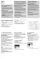
z Sicherheitshinweise
– Anleitung lesen!
Bevor Sie mit dem Netzteil arbeiten,
lesen Sie diese Anleitung komplett
durch. Stellen Sie sicher, daß Sie alles
verstanden haben. Hinweise am Gerät
beachten.
– Anlage freischalten!
Vor Installations-, Wartungs- oder Ände-
rungsarbeiten: Schalten Sie Ihre Anlage
spannungsfrei. Stellen Sie sicher, daß sie
nicht versehentlich wieder eingeschaltet
werden kann.
– Vor Inbetriebnahme: Fachgerecht
installieren
Achtung! Unsachgemäße
Installation/Betrieb kann die Sicherheit
beeinträchtigen und zu Betriebsstörungen
bis hin zur Zerstörung des Gerätes führen.
Die Installation und Inbetriebnahme darf
nur durch entsprechend qualifiziertes Fach-
personal erfolgen. Hierbei sind die einschlä-
gigen Vorschriften (DIN, VDE bzw.
landesspezifische Vorschriften) und die im
Abschnitt „Installation“ unter „2. Montage,
Inbetriebnahme und Demontage“ stehen-
den Hinweise zu beachten.
– Im Betrieb: Nichts ändern!
Solange sich das Gerät in Betrieb befin-
det: Keinerlei Änderungen an der Installa-
tion vornehmen! Dies gilt auch für die
Sekundärseite. Gefahr von Lichtbögen
und elektrischem Schlag (Lebensgefahr)!
– Verbrennungsgefahr
Gerät wird heiß (vor allem Rückseite und
Seitenflächen). Im Betrieb und kurz
danach nicht berühren!
– Konvektionskühlung
Obere und untere Wandfläche nicht ver-
decken!
Um das Gerät herum genügend Freiraum
zur Kühlung lassen.
– Schrauben: nicht entfernen
Die Schrauben am Gehäuse dienen der
internen Erdung. Nicht entfernen!
– Achtung: Hochspannung!
Gespeicherte Energie
Das Gerät darf nur durch entsprechend
geschultes Personal geöffnet werden!
Keine Gegenstände in das Gerät ein-
führen! Das Gerät enthält ungeschützte
Leiter unter lebensgefährlicher Hochspan-
nung sowie Bauelemente, die sehr viel
Energie speichern (deshalb das Gerät
frühestens 5 Minuten nach allpoligem
Abtrennen vom Netz öffnen!).
Unsachgemäßer Umgang kann zu Strom-
schlag oder schweren Verbrennungen
führen.
– Einsatzgebiete
Das Hutschienen-Netzteil RPS60 darf nur
mit Geräten betrieben werden, wenn auf
deren Typenschild die Netzspannung 24
VDC eingetragen ist.
1. Funktionsbeschreibung
1.1 ALLGEMEINE FUNKTIONEN UND
EIGENSCHAFTEN
Quasi Wide-Range Input
Bei geringer und mittlerer Belastung kommt
das RPS60 auch in der Schalterstellung
230V mit 115V und weniger aus.
Einfache Absicherung
Leitungsschutzschalter genügen dank akti-
ver Eingangsstrombegrenzung, die auch bei
warmem Gerät voll funktionsfähig ist.
Overload Design
Weder Abschalten noch Hiccup bei Über-
last, und in der Strombegrenzung fließt
mindestens der Nennstrom, meist sogar
deutlich mehr.
20…25% Leistungsreserve
bei 60°C für 1 Min., bei 45 °C sogar dauer-
haft.
EMV
Das RPS erfüllt die EMV-Normen in der
jeweils schärfsten Klasse und eignet sich
daher für den Wohn- sowie für den Indus-
triebereich.
Ausgangsentstörung
Der Ausgang ist funkentstört, so daß auch
lange, ungeschirmte Leitungen nicht
abstrahlen.
Sitz auf der Hutschiene
Dank TS-Halterung einfachste Montage,
aber absolut sicherer Sitz, selbst bei Rütteln
und seitlichem Druck. Demontage einfach
per Knopfdruck.
Paralellschaltbarkeit
Die RPS60-Geräte sind parallel schaltbar
und können auf Wunsch den Laststrom
gleichmäßig unter sich aufteilen.
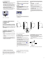
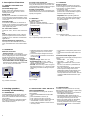
1.2 ANZEIGENELEMENTE
P – Power (Grüne LED)
Betriebsanzeige
– leuchtet bei Normalbetrieb
–
erlischt bei starker Überlast od. Kurzschluß
Abb. 1: Betriebsanzeige (Power LED)
P
+24V 12,5A
Betriebsanzeige
1.3 BEDIENELEMENTE
Wahlschalter
Paßt Netzteil an die gegebene Netzspan-
nung an (vgl. „zulässige Belastung“ im
Abschnitt „4. Technische Daten“).
– Voreingestellt: 230 V.
– An Netzen mit 115 V AC: Schalterstellung
115 V empfohlen (längere Pufferzeit, bes-
serer Wirkungsgrad).
–
Wichtig: Bei Betrieb mit Gleichspannung
muß der Schalter in der Position 230 V
stehen (andernfalls kann das Netzteil
Schaden nehmen).
Abb. 2: Wahlschalter,
(hier: Schalterstellung auf 230V)
V
in
115 V AC 1,3 A 60 Hz
230V
V
in
230 V AC 0,7 A 50 Hz
Wahlschalter
115V, 230V
Sicherheitsaufkleber am Gerät
➀ Wichtig: Vor Inbetriebnahme Anleitung
lesen!
② Zulässiger Einsatzbereich (siehe Tabelle
„Technische Daten“)
➂ Kabelquerschnitt 0,5…4 mm
2
, 6 mm abi-
solieren.
➃ Sicherstellen, daß alle Feindrähte in der
Klemme befestigt sind.
➄ Nicht ohne Schutzleiter betreiben.
➅ Ausgangspolarität beachten!
➆ Betrifft Öffnen des Gerätes, siehe „Sicher-
heitshinweise“.
➇ Nach Verwendung dem Recycling
zuführen
⑨ Zulässiger Temperaturbereich
➉ Konvektionskühlung nicht behindern!
Von Feuer und Wasser fernhalten!
D

3
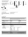
2. Montage, Inbetriebnahme
und Demontage
2.1 EINBAU
Montieren Sie das RPS60 nur wie abgebil-
det, mit den Eingangsklemmen nach unten.
Sonst ist keine ausreichende Kühlung mög-
lich.
Stellen Sie den Freiraum zur Kühlung sicher
(empfohlene Abstände siehe Tabelle „Tech-
nische Daten“).
2.2 MONTAGE – RPS 60 AUF TRAG-
SCHIENE AUFSCHNAPPEN
Zulässige DIN-Tragschiene: TS35/7,5 oder
TS35/15.
M Kippen Sie das RPS60 leicht nach hinten
(➀).
M
Setzen Sie das RPS60 auf die Hutschiene
auf (②).
M
Schieben Sie es bis zum Anschlag nach
unten (➂).
M
Drücken Sie unten gegen die Vorderseite
des RPS60, um es zu verriegeln (➃).
M
Rütteln Sie leicht am RPS60, um die Ver-
riegelung zu überprüfen.
➀ ② ➂ ➃
3. Weitere Unterstützung
Bei technischen Fragen wenden Sie sich
bitte an den Hirschmann-Vertragspartner in
Ihrer Nähe oder direkt an Hirschmann. Die
Adressen unserer Vertragspartner finden
Sie
2.3 INSTALLATION
Vor der Inbetriebnahme ist eine fachgerech-
te Installation durchzuführen. Insbesondere
ist sicherzustellen, daß
– der Netzanschluß gemäß VDE0100 und
VDE0160 erfolgt.
– bei flexiblen Kabeln alle Feindrähte in den
Anschlußklemmen befestigt sind (Gefahr
von Gehäuseschluß).
– Gerät und Zuleitungen ausreichend abge-
sichert werden und im Bedarfsfall auch
von Hand freigeschaltet werden können.
– der Schutzleiter an der Klemme ange-
schlossen wird.
– alle Ausgangsleitungen für den Ausgangs-
strom des Netzteils ausgelegt sind und
polrichtig angeschlossen werden.
– eine ausreichende Kühlung gewährleistet
ist.
2.4 DEMONTAGE – RPS 60 VON DER
TRAGSCHIENE ABNEHMEN
M Drücken Sie zum Entriegeln den Knopf an
der Oberseite des RPS60 nach unten
(siehe Abbildung 6).
M Nehmen Sie das Gerät von der Hutschie-
ne ab.
Abb. 6: Knopf zum Entriegeln des RPS60
Abb. 5: Montage des RPS60
1.4 SCHNITTSTELLEN
Netzanschluß
– Externe Absicherung: ist nicht erforder-
lich. Die interne Sicherung ist nicht
zugänglich, da sie nicht durch den Anwen-
der ausgetauscht werden darf. Sollte
diese interne Sicherung auslösen, weist
das Gerät einen internen Defekt aus und
muß aus Sicherheitsgründen an den Her-
steller eingeschickt werden.
– Empfehlung für die Zuleitung: Lei-
tungsschutzschalter mit B-Charakteristik
(oder träger), Sicherungswert 10 A.
Abb. 3: Netzanschluß
V
in
115 V AC 1,3 A 60 Hz
230V
V
in
230 V AC 0,7 A 50 Hz
N L
Netzanschluß
M Stellen Sie sicher, daß der Wahlschalter
(siehe Abb. 2) auf der richtigen Stellung
steht.
M Schließen Sie die Eingangsspannung an
die Klemmen N, L und den Schutzleiter
an die Klemme an.
Ausgang
– Ausgangsspannung: 24VDC +5% -1%
– Zulässige Belastung: bei -10°C…+60°C
und Konvektionskühlung siehe Tabelle
Technische Daten
– Erdung: Die Sekundärseite ist nicht geer-
det, daher kann bei Bedarf wahlweise die
+ oder - Klemme geerdet werden.
Abb. 4: Ausgang
M Beachten Sie die Polung der Klemmen!
M Schließen Sie die Anschlußleitungen am
Ausgang an.
P
+24V 12,5A
P
+24V 12,5A
Anschlußleitungen Eingang/Ausgang
Für Eingang und Ausgang gelten folgende
Werte:
– flexible Kabel: 1,5…4 mm
2
– starre Kabel: 1,5…6 mm
2
– Abisolieren am Kabelende: 6 mm (nicht
länger!)
An den Ausgangsklemmen sind auch
0,5 mm
2
Querschnitt zulässig.
Verwenden Sie nur handelsübliche, für
die gegebenen Spannungen und Ströme
ausgelegten Kabel.
Bei flexiblen Kabeln: Stellen Sie sicher,
daß alle Feindrähte des Kabels in der
Klemme befestigt sind. Die Verwendung
von geeigneten Adernendhülsen ist zuläs-
sig.
– im Internet (http://www.hirschmann.de).
Darüber hinaus steht Ihnen unsere Hotline
zur Verfügung:
Tel. +49(7127) 14-1538 (Fax -1542)

4
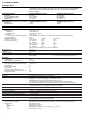
4. Technische Daten
Allgemeine Daten
Einsatzbereich RPS60 Hutschienennetzteile sind primär getaktete Schaltnetzteile zur Einbau-Montage,
ausgelegt für professionelle Anwendungen. Sie dürfen im Betrieb nicht frei zugänglich
sein. Installation und Inbetriebnahme dürfen nur durch entsprechend qualifiziertes
Personal erfolgen.
Eingangsspannung Schalterstellung auf 230 V Schalterstellung auf 115 V
Nennwert AC 230 V AC 115/230 V
AC Dauerbetrieb (Vollast) 176 - 264 VAC 85 - 132 VAC
DC Dauerbetrieb (Vollast) 160 - 375 VDC Nicht zulässig!
Netzfrequenz 47 - 63 Hz 47 - 63 Hz
Eingangsstrom (bei 264 VAC und Kaltstart) Schalterstellung auf 230 V Schalterstellung auf 115 V
Nennwert < 0,7 A < 1,3 A
Einschaltstrom < 25 A < 25 A
Pufferzeit > 20 ms (196 VAC)
Überstromschutz im Eingang interne Sicherung
Ausgang kurzschluß-, leerlauf- und überlastfest
Nennspannung 24 VDC +5% -1%
Toleranz 62% über alles
Restwelligkeit < 25 mV
ss
incl. Spikes
Nennstrom 2,5 A (60 W)
Leistungsreserve/Überlastverhalten Overload Design, siehe Kap. 1.1 „Allgemeine Funktionen und Eigenschaften“
Ausgangsfrequenz 0 Hz
Zulässige Belastung AC/DC
in
Schalter I
out
bei 24 V
(bei -10°C…+60°C und 176 - 264 VAC 230V 2,5 A
Konvektionskühlung) 95 - 176 VAC 230 V 1,5 A
85 - 132 VAC 115 V 2,5 A
160 - 375 VDC 230 V 2,5 A
120 - 160 VDC 230 V 2,0 A
80 - 120 VDC 230 V 1,5 A
(Zum Start mit DC Eingang > 95 VDC erforderlich)
Wirkungsgrad typ. 87,5 %
Verluste typ. 8,6 W
Parallel schaltbar ja
Anschlußleitungen (Eingang und Ausgang) flexible Kabel: 1,5…4 mm
2
(am Ausgang auch 0,5 mm
2
)
starre Kabel: 1,5…6 mm
2
(am Ausgang auch 0,5 mm
2
)
Regelung
Genauigkeit 2%
Restwelligkeit (Einzelbetrieb) < 25 mV
ss
Schutzfunktionen
Überspannungsschutz (Sekundärseite) ja, typ. 32 V
Überlastfest ja
Dauerkurzschlußfest ja
Leerlauffest ja
Transientenfest (VDE 0160 / W2) ja
Interne Eingangssicherung (s. Kap. 1.4) ja
Rückspeisefest bis 26 V
Betriebsanzeige P: Power, grüne LED
Montage auf DIN-Tragschiene TS35/7,5 oder TS35/15
Anschluß Schraubklemmen, Klemmbereich starr/flexibel:
Eingang 1,5…6 mm
2
, Ausgang 0,5…6 mm
2
/0,5…4 mm
2
Doppelklemmen am Ausgang, belastbar jeweils bis 30 A
Alle Klemmen potentialfrei, daher auch Pluspol für Masse/Erdung geeignet
Ein-/Ausgang klar getrennt und gut lesbar beschriftet, keine Verwechslungsgefahr
Gehäuse Rundum geschlossenes Metallgehäuse mit engmaschigem Lüftungsgitter
(verhindert Eindringen von Kleinteilen wie z.B. Schrauben)
Abmessungen B x H x T (mm) 50 x 125 x 103
Gewicht 460 g
Freiraum (empfohlen) links 0 mm, oben/unten je 25 mm, rechts 10 mm
Betriebstemperatur -10 °C bis +60 °C (Vollast)
Temperaturbereich Lagerung/Transport –25 °C bis +85 °C
Luftfeuchtigkeit 10% bis 90% (nicht kondensierend)
Schutzart Lagerung/Transport/Betrieb: IP20 gem. EN60529
Vor Feuchtigkeit (auch Betauung) schützen!
EMV
Störaussendung, geleitet EN 50081-1 und -2 (Klasse B) incl. EN 50081-1, Anhang A (Ausgangsentstörung)
Störfestigkeit EN 50082-1 und -2
ESD EN 61000-4-2, Level 4
Einstrahlung ENV 50140, Level 3
Burst EN 61000-4-4 (IEC801-4), AC
in
: Level 4, DC
out
: Level 3
Surge EN 61000-4-5, Class 4

5
Geleitete Störfestigkeit ENV 50141, Level 3
Transientenfestigkeit VDE 0160/W2 (für jeden Lastfall)
Sicherheit
Schutzklasse 1 (IEC 536)
Schutzart IP20 gem. EN 60529
Sicherheitskleinspannung SELV gem. EN 60950 und VDE 0100 Teil 410, PELV gem. VDE 0160
Normen/Zulassungen
VDE 0160, EN 60950 (LGA), EN 55011
UL 1950, UL 0508, CUL CSA-C22.2 No. 234-M90, EN 50178
c CE-Kennzeichnung erfolgt nach EMV-Richtlinie und Niederspannungsrichtlinie.
Lieferumfang
Hutschienen-Netzteil RPS60
Bestellnummer RPS60 943 662-001
Zubehör
Handbuch Ethernet 943 320-001
z Safety instructions
– Read the instructions!
Before you start working on the power
module, read the operating instructions
completely. Make sure that you have
understood everything. Pay attention to
the instructions on the device.
– Isolate system from mains!
When installing, servicing or making
modifications: Isolate your system from
the mains supply! Make sure that the
system cannot be turned on again acci-
dentally.
– Before starting operation: Installing
correctly
Caution: Improper installation can impair
safety and can lead to system failure or
even to the destruction of the device.
GB
Installation and starting up may only be car-
ried out by qualified personnel. The appro-
priate regulations (DIN, VDE and national
regulations) found in the Sections "Installa-
tion“ under "2. Installation, set up and
assembly instructions", must be observed.
– While in operation: Do not make any
alterations!
As long as the device is in operation: Do
not carry out any changes to the installati-
on whatsoever. This also applies to the
secondary side. Danger of electric arcs or
electrical shocks. (potentially fatal)
– Risk of burns
The device gets hot (above all on the back
and at the sides). Do not touch the device
during or shortly after operation!
– Convection cooling
Do not cover the upper and lower panel
areas!
Make sure there is adequate space all
around the device for cooling.
– Screws: Do not remove
The screws on the housing form part of
the internal grounding. Do not remove!
– Caution: High voltage!
Stored energy
The device can only be opened by trained
personnel!
Do not insert objects into the device!
The device contains unprotected conduc-
tors with a high voltage that can kill and
components that can store large amounts
of energy. (For this reason, do not open
the device until 5 minutes after the com-
plete disconnection from the mains supp-
ly)
Improper handling can lead to an electric
shock or severe burns.
– Range of application
RPS60 rail power module can only be ope-
rated with those devices with a line volta-
ge of 24 VDC specified on their type plate.
Safety sticker on the device
➀ Important: Before putting into operation
read the operating instructions!
② Permissible operative range (see Table
"Technical data“)
➂ Cable cross section 0,5…4 mm
2
, strip 6
mm.
➃ Make sure that all the fine wires are secu-
red in the terminal
➄ Do not operate without protective con-
ductor.
➅ Note the output polarity!
➆ With regards to opening the device, see
the "Safety instructions“.
➇ After use, hand over for recycling
⑨ Permissible temperature range
➉ Do not restrict convection cooling!
Keep away from fire and water
,
Recycling Hinweis:
Dieses Produkt ist nach seiner Ver-
wendung entsprechend den aktuel-
len Entsorgungsvorschriften Ihres
Landkreises/Landes/Staates als
Elektronikschrott einer geordneten
Entsorgung zuzuführen.

6
2. Starting operation,
Assembly and dismantling
2.1 INTEGRATION
Install the RPS60 only as shown in the dia-
gram, with the input terminals pointing
downward. Otherwise sufficient cooling is
not possible.
Make sure that there is enough free space
for cooling (recommended spacing see
Table "Technical data“).
1. Description of functions
1.1 GENERAL FUNCTIONS AND
FEATURES
Quasi Wide-Range Input
With a smaller and moderate load, the
RPS60 can run on 115V or less, even in
switch position 230V.
Easily fused
Miniature circuit breakers are sufficient due
to the active input current limitation, which
is also completely functional when the devi-
ce is warm.
Overload Design
In the event of overload, no shut-down or
hiccup occurs and at the very least the rated
current flows in the current limiting reactor,
often significantly more.
20…25% Power reserve
at 60°C for 1 min., at 45 °C even continuous-
ly.
EMC
The RPS fulfills the EMC norms in the res-
pective toughest classes and is therefore
suitable for use in domestic and industrial
applications.
Output interference suppression
The output is radio shielded so that even
long, unshielded wires cannot emit radiati-
on.
2.2 INSTALLATION - SNAP THE RPS 60
ONTO MOUNTING RAIL
Permissible DIN mounting rails: TS35/7,5
oder TS35/15.
M Gently tilt the RPS60 backwards a little
(➀).
M
Place the RPS60 on the rail (②).
M
Push it down as far as it will go (➂).
M
Push against the bottom of the front side
of the RPS60, in order to lock it (➃).
M
Gently shake the RPS60 to check that it is
securely locked.
2.3 INSTALLATION
Installation must be carried out correctly,
before putting into operation. In particularly
important to make sure that
– The network connection is in accordance
with VDE0100 and VDE0160.
– with flexible cables, all fine wires are
securely fastened in the connection termi-
nal (danger of housing short circuit).
– Device and supply leads are adequately
fused and if the need arises can be
manually isolated from the power supply.
– the protective conductor is connected to
the terminal .
Securing to the top hat rail.
Due to TS mounting brackets, installation is
easy yet absolutely secure, even when sub-
ject to vibrations or lateral pressure. Simple
dismantling at the touch of a button.
Parallel connectability
The RPS60 devices can be connected in par-
allel and the load current can be distributed
equally among them.
1.2 DISPLAYS
P – Power (Green LED)
Operating display
– lights up in normal operation
– goes out in the event of severe overload
or short-circuits.
Fig. 1: Operating display (Power LED)
P
+24V 12,5A
Operating display
1.3 CONTROLS
Selector switch
Adapts the power modules to the actual
mains voltage (compare "permissible load“
in the Section "4. Technical data“)
– Pre-settings: 230 V.
– To the mains supply at 115 V AC: Switch
position 115 V recommended (longer buf-
fer time, improved efficiency).
– Important: When operating with the
direct current, the switch must be at posi-
tion 230 V (otherwise the power supply
may be damaged).
Fig. 2: Selector switch
(in this case: switch position on 230V)
V
in
115 V AC 1,3 A 60 Hz
230V
V
in
230 V AC 0,7 A 50 Hz
Selector switch
115V, 230V
1.4 INTERFACES
Network connection
– External fusing: is not necessary.
The internal fuse is not accessible as it may
not be changed by the user. If the internal
fuse blows, the device has an internal
defect. In this case, for reasons of safety, it
must be sent back to the manufacturer.
– Recommendation for the supply lead:
Miniature circuit breaker with B characteri-
stic (or carrier), fuse value 10A
Fig. 3: Mains connection
V
in
115 V AC 1,3 A 60 Hz
230V
V
in
230 V AC 0,7 A 50 Hz
N L
Mains connection
M Make absolutely sure, that the selector
switch (see Figure 2) is in the correct
position.
M Connect the input voltage to the termi-
nals N, L and the protective conductor to
the terminal .
Ausgang
– Output voltage: 24VDC +5% -1%
– Permissible load: at -10°C…+60°C
(
+14°F…+140°F
)
and convection cooling
see Table: Technical data
– Ground: The secondary side is not groun-
ded, that means the + or - terminal can be
optionally grounded according to require-
ments.
Fig. 4: Output
P
+24V 12,5A
P
+24V 12,5A
M Pay attention to the polarity of the termi-
nals!
M Connect the connection leads to the out-
put.
Connection leads input/output
The following values apply to the input and
output:
– flexible cable: 1,5…4 mm
2
– rigid cable: 1,5…6 mm
2
– stripping the cable ends: 6 mm (not lon-
ger!)
0.5 mm
2
cross section is permissible on
the output terminal.
Only use conventional cables designed
for the specific voltage and current.
With flexible cables: Make perfectly sure
that all the fine wires of the cable are
securely fastened in the terminal. The use
of other suitable terminal sleeves is per-
missible.

7
➀ ② ➂ ➃
3. Further support
For technical questions, please contact any
Hirschmann dealer in your area or Hirsch-
mann directly. You will find our list of our
dealers
Fig. 5: Mounting the RPS60
– in the Internet(http://www.hirschmann.de).
Our Hotline is also available.
Tel. +49 7127-14-1538
Fax +49 7127-14-1542
4. Technical data
Allgemeine Daten
General data The primary area of application of the RPS60 rail - power modules is primarily switched-
mode serial power modules for the modular installation, designed for professional
applications. They may not be accessible when in operation. Installation and starting
operation may only be carried out by qualified personnel.
Input voltage Switch setting to 230V Switch setting to 115V
Rated value AC 230 V AC 115/230 V
AC continuous running (full load) 176 - 264 VAC 85 - 132 VAC
DC continuous running (full load) 160 - 375 VDC not permissible!
Mains frequency 47 - 63 Hz 47 - 63 Hz
Input current (at 264 VAC and cold start) Switch setting to 230V Switch setting to
Rated value < 0.7 A < 1.3 A
Activation current < 25 A < 25 A
Buffer time > 20 ms (196 VAC)
Overcurrent protection in the input Internal fuse
Output short-circuit, idle running and overload proof
Rated voltage 24 VDC +5% -1%
Tolerance 62% above everything
Residual ripple < 25 mV
ss
incl. Spikes
Rated current 2.5 A (60 W)
Reserve capacity/overload behavior Overload Design, see Chapter. 1.1 "General functions and features“
Output frequency 0 Hz
Permissible load AC/DC
in
Switch I
out
with 24 V
(at -10°C…+60°C and 176 - 264 VAC 230V 2.5 A
Convection cooling) 95 - 176 VAC 230 V 1.5 A
85 - 132 VAC 115 V 2.5 A
160 - 375 VDC 230 V 2.5 A
120 - 160 VDC 230 V 2.0 A
80 - 120 VDC 230 V 1.5 A
(To start with the DC input > 95 VDC is necessary)
Efficiency type 87.5 %
Losses type 8.6 W
Connectable in parallel yes
Connection leads (input and output) flexible cable: 1.5…4 mm
2
(on the output also 0.5 mm
2
)
fixed/rigid cable: 1.5…6 mm
2
(at the output also 0.5 mm
2
)
– all output lines are designed for the out-
put current of the power module and
connected with the correct polarity.
– adequate cooling is guaranteed.
2.4 REMOVAL – TAKING THE RPS 60
OFF THE MOUNTING RAIL
M To unlock, press the button on the top the
RPS60 (see Fig. 6).
M Take the device off the rail.
Fig. 6: Button to unlock the RPS60

Richard Hirschmann GmbH & Co.
Automation and Networking Solutions
Stuttgarter Str. 45-51
D-72654 Neckartenzlingen
Telephone ++49 (0)7127 14 1538
Printed in Federal Republic of Germany
039615001010899000
Regulation
Precision 2%
Residual ripple (single operation) < 25 mV
ss
Safety functions
Overvoltage protection (secondary) yes, type 32 V
Overload proof yes
Continuous short circuit proof yes
Idle running proof yes
Transient proof (VDE 0160 / W2) yes
Internal input fuse (see Chapter 1.4) yes
Feedback proof 26 V
Operating display P: Power, green LED
Assembly on DIN mounting rail TS35/7.5 or TS35/15
Connection Screw terminals, terminal range rigid/flexible:
Input 1.5…6 mm
2
, Output 0.5…6 mm
2
/0.5…4 mm
2
Double terminal at output, each capable of accepting up to 30A
All terminals potential-free, therefore even the plus pole suitable for grounding.
Input and output clearly separated and highly legible, no danger of swapping over.
Housing Completely enclosed metal housing with narrow mesh ventilation grate
(penetration by small objects e.g. screws, prevented)
Dimensions W x H x D 50 mm x 125 mm x 103 mm (1.97 in x 4.92 in x 4.06 in)
Weight 460 g (1.013 lb)
Free space (recommended) left 0 mm (0 in), above/below 25 mm (0,98 in), right 10 mm (0,39 in)
Operating temperature -10 °C to +60 °C (full load) (+14 °F to +140 °F)
Temperature field storage/transport –25 °C to +85 °C (-13 °F to +185 °F)
Humidity 10% to 90% (non condensing)
Type of protection Storage/transport/operating IP20 according to EN60529
Protect from humidity (also condensation)
EMC
Emitted interference, conducted EN 50081-1 and -2 (classe B) incl. EN 50081-1, Appendix A (output fault suppression)
Interference proof EN 50082-1 and -2
ESD EN 61000-4-2, Level 4
Irradiation ENV 50140, Level 3
Burst EN 61000-4-4 (IEC801-4), AC
in
: Level 4, DC
out
: Level 3
Surge EN 61000-4-5, Class 4
conducted interference proof ENV 50141, Level 3
Transient proof resistance to VDE 0160/W2 (for every load)
Safety
Protector class 1 (IEC 536)
Protection IP20 according to EN 60529
Safety current SELV according to EN 60950 and VDE 0100 part 410, PELV according to VDE 0160
Norms/Licenses
VDE 0160, EN 60950 (LGA), EN 55011
UL 1950, UL 0508, CUL CSA-C22.2 No. 234-M90, EN 50178
c CE marking achieved in accordance with EMC guideline and low current guideline.
Scope of delivery
RPS60 rail power supply unit
Order number RPS60 943 662-001
Accessories
Ethernet manual 943 320-001
,
Recycling Note:
After its use, this product has to be
processed as electronique scrap to a
proper disposal according to the pre-
vailing waste disposal regulations of
your community/district/country/
state.
-
 1
1
-
 2
2
-
 3
3
-
 4
4
-
 5
5
-
 6
6
-
 7
7
-
 8
8


Hirschmann RPS60 Benutzerhandbuch
- Typ
- Benutzerhandbuch
- Dieses Handbuch eignet sich auch für
in anderen Sprachen
- English: Hirschmann RPS60 User manual
Verwandte Artikel
Andere Dokumente
-
BEL LET480 Installationsanleitung
-
ABB CP-E 5/3.0 Bedienungsanleitung
-
Baumer Power Supply DIN Rail 24V/60W Datenblatt
-
-
-
-
Eurotherm 2500P - 5A0 Bedienungsanleitung
-
-
-