LDN240-12
INPUT:
120 / 240 VAC, 4 / 2 A, 50 - 60 Hz
OUTPUT:
12 VDC, 16 A
LDN240-24
INPUT:
120 / 240 VAC, 4 / 2 A, 50 - 60 Hz
OUTPUT:
24 VDC, 10 A
LDN240-24P
INPUT:
120 / 240 VAC, 4 / 2 A, 50 - 60 Hz
OUTPUT:
24 VDC, 10 A + ORing circuit
LDN240-48P
INPUT:
120 / 240 VAC, 4 / 2 A, 50 - 60 Hz
OUTPUT:
48 VDC, 5 A + ORing circuit
LDN240-72P
INPUT:
120 / 240 VAC, 4 / 2 A, 50 - 60 Hz
OUTPUT:
72 VDC, 3.5 A + ORing circuit
MAIN FEATURES
• High efficiency and compact size
• Overload 130%
• Only 63 mm width aluminum enclosure
• Up to 50°C operating temperature with no derating
READ THIS CAREFULLY BEFORE
INSTALLATION!
VOR DER INSTALLATION BITTE FOLGENDE
SICHERHEITSHINWEISE BEACHTEN!
LEGGERE ATTENTAMENTE PRIMA
DELL’INSTALLAZIONE!
A LIRE ATTENTIVEMENT AVANT
L’INSTALLATION!
Before operating, read this document
thoroughly and retain it for future reference.
Non-respect of these instructions may reduce
performances and safety of the devices and
cause danger for people and property.
The products must be installed, operated,
serviced and maintained by qualified
personnel in compliance with applicable
standards and regulations.
Do not open the device, it does not contain
replaceable components, the tripping of the
internal fuse (if included) is caused by an
internal failure.
Do not repair or modify the device, if
malfunction or failure should occur during
operation, send unit to the factory for
inspection.
No responsibility is assumed by Bel for any
consequences deriving from the use of this
material.
Lesen Sie dieses Dokument vor der
Inbetriebnahme sorgfältig durch und bewahren Sie
es zum späteren Nachschlagen auf.
Die Nichtbeachtung dieser Anweisungen kann die
Funktion und Sicherheit der Geräte beeinträchtigen
und birgt Gefahren für Personen und Eigentum.
Die Geräte müssen von qualifiziertem Personal
unter Einhaltung der geltenden Normen und
Vorschriften installiert, betrieben, gewartet und
instand gehalten werden.
Öffnen Sie das Gerät nicht, es enthält keine
austauschbaren Komponenten, das Auslösen der
internen Sicherung (falls vorhanden) ist stets auf
tiefergehende Fehler im Schaltkreis zurück zu
führen.
Reparieren oder modifizieren Sie das Gerät nicht.
Sollte während des Betriebs eine Fehlfunktion oder
ein Defekt auftreten, schicken Sie das Gerät zur
Überprüfung ins Werk.
Bel übernimmt keine Haftung für die Folgen, die
sich aus dem Einsatz dieses Gerätes ergeben.
Prima dell’installazione, leggere attentamente
questo documento istruzioni e conservarle per
future consultazioni.
L’inosservanza delle presenti istruzioni può
compromettere le caratteristiche e la
sicurezza dell’apparecchio e causare pericolo
per le persone e le cose.
Il prodotto deve essere installato, utilizzato e
riparato da personale qualificato e nel rispetto
delle normative vigenti.
Non aprire il prodotto, esso non contiene
componenti sostituibili, il guasto del fusibile
interno (se previsto) è causato da un guasto
interno.
Non tentare di riparare o modificare il
prodotto, se durante il funzionamento si
verificano guasti o anomalie, inviarlo al
produttore per il controllo.
Bel non si assume nessuna responsabilità per
qualunque conseguenza derivante dall’uso di
questo materiale.
Lire ces instructions avant l'installation,
conserver ce manuel pour référence future.
Défaut de se conformer à ces instructions
peut affecter les caractéristiques et la sécurité
du dispositif, et causer du danger aux
personnes ou aux biens.
Les produits doivent être installés, exploités
et entretenus par du personnel qualifié et en
conformité avec les règlements.
N'ouvrez pas le produit, il ne contient aucune
pièce réparable, le déclenchement du fusible
interne (le cas échéant) est causé par un
défaut interne.
Ne pas essayer de réparer ou modifier le
produit ; si des défaillances se produisent
pendant le fonctionnement, retourner le
produit au fabricant pour inspection.
Bel n'assume aucune responsabilité des
conséquences éventuelles découlant de
l'utilisation des produits.
CAUTION
ACHTUNG
ATTENZIONE
AVVERTISSEMENT
RISK OF BURNS, EXPLOSION, FIRE,
ELECTRICAL SHOCK, PERSONAL INJURY.
Never carry out work on live parts! Danger of
fatal injury!
The product’s enclosure may be hot, allow
time for cooling product before touching it.
Do not allow liquids or foreign objects to enter
into the products.
To avoid sparks, do not connect or
disconnect the device before having
previously turned-off input power and wait for
internal capacitors discharge (minimum 1
minute).
GEFAHR VON VERBRENNUNGEN,
EXPLOSIONEN, FEUER, STROMSCHLAG,
PERSONENSCHÄDEN.
Führen Sie niemals Arbeiten an
spannungsführenden Teilen durch! Gefahr von
tödlichen Verletzungen! Das Gehäuse des Gerätes
kann heiß sein, lassen Sie Zeit zum Abkühlen des
Gerätes, bevor Sie es berühren.
Lassen Sie keine Flüssigkeiten oder Fremdkörper
in die Geräte eindringen.
Um Überschläge zu vermeiden, schließen Sie das
Gerät nicht an oder trennen Sie es nicht ohne
vorher die Eingangsspannung abgeschaltet zu
haben, und warten Sie die Entladung der internen
Kondensatoren ab (mindestens 1 Minute).
RISCHIO USTIONI, ESPLOSIONE,
INCENDIO, SCOSSA, LESIONI GRAVI.
Non effettuare mai operazioni sulle parti sotto
tensione! Pericolo di lesioni letali!
Il contenitore può scottare, lasciar quindi
raffreddare il dispositivo prima di toccarlo.
Non far entrare liquidi o oggetti estranei nel
dispositivo.
Per evitare scintille, non collegare o scollegare
l'apparecchiatura prima di avere tolto tensione
di ingresso e prima che sia avvenuta la
scarica dei condensatori interni (min. 1
minuto).
RISQUE DE BRULURES, EXPLOSION,
INCENDIE, ELECTROCUTION, DOMMAGE
AUX PERSONNES.
Ne jamais effectuer des opérations sur les
parties sous tension! Danger de mort!
Le boîtier peut produire des brûlures, le
laisser refroidir avant de toucher l'appareil. Ne
faire pas pénétrer des liquides ou des corps
étrangers dans l'appareil.
Pour éviter des étincelles, ne pas connecter
ou déconnecter l'équipement jusqu'à ce que
la tension d'entrée a été supprimée et avant
qu'il n'ait eut lieu la décharge des
condensateurs internes (minimum 1 minute).
INTENDED USE
BESTIMMUNGSGEMÄßER BETRIEB
USO PREVISTO
UTILISATION
These are isolated devices suitable for SELV
and PELV circuitry and are designed to be
mounted on DIN rail and installed inside a
protective enclosure. They are intended for
general use such as in industrial control,
communication, and instrumentation
equipment.
Do not use these devices in applications
where malfunction may cause injury or death.
Es handelt sich um galvanisch getrennte Geräte,
die für SELV- und PELV-Anwendungen geeignet
sind und für die Montage auf DIN-Schienen und die
Installation in einem Schutzgehäuse konzipiert
sind. Sie sind für den allgemeinen Gebrauch wie
z.B. in industriellen Steuer-, Kommunikations- und
Automatisierung-Anwendungen vorgesehen.
Verwenden Sie diese Geräte nicht in
Anwendungen, bei denen eine Fehlfunktion zu
Verletzungen oder zum Tod führen kann.
I dispositivi sono isolati, adatti per applicazioni
SELV e PELV, sono dotati di aggancio per il
montaggio su guida DIN all’interno di quadri
elettrici o contenitori di protezione, per
l’utilizzo con controllori industriali, unità di
comunicazione o apparecchi di misura.
Non utilizzare in applicazioni in cui un
eventuale guasto può comportare rischio di
lesioni o di morte.
Les produits sont isolés, appropriés pour les
circuits TBTS et TBTP et sont équipés d'un
crochet pour montage sur rail DIN dans des
armoires ou conteneurs de protection, pour
utilisation avec les contrôleurs industriels, des
modules de communication ou des unités de
mesure.
Ne pas utiliser ces dispositifs dans une
application où un dysfonctionnement pourrait
entraîner le risque des blessures ou de mort.
ENVIRONMENTAL CHARACTERISTICS
UMGEBUNGSBEDINGUNGEN
CARATTERISTICHE AMBIENTALI
CARACTÉRISTIQUES ENVIRONMENTALES
Installation in a Pollution Degree 2
environment.
Do not use in wet area or subject to moisture.
Carefully recycle the product and related
batteries according to local regulations.
Installation in einer Umgebung mit
Verschmutzungsgrad 2.
Nicht in nassen Bereichen oder unter Feuchtigkeit
verwenden.
Das Gerät und die zugehörigen Batterien sind
entsprechend den lokalen Vorschriften zu recyceln
bzw. zu entsorgen.
Usare in ambienti con Grado di Inquinamento
2.
Non far funzionare l'apparecchio in un
ambiente umido o soggetto a formazione di
condensa. Riciclare il prodotto e le batterie
collegate, nel rispetto delle normative locali
vigenti.
Utiliser les produits dans des environnements
avec degré de pollution 2.
Ne pas employer l'appareil dans un
environnement humide ou soumis à la
condensation. Recycler les produits et les
batteries, conformément à la réglementation
locale.

Manufacturer
Bel Fuse Inc.
300 Executive Drive, Suite 300
West Orange, NJ 07052
USA
Asia-Pacific
+86 755 2988 5888
Europe, Middle East
+353 61 49 8941
North America
+1 866 513 2839
belfuse.com/power-solutions
© 2023 Bel Fuse Inc.
BCM.00403_AF
USER INSTRUCTIONS
1) DESCRIPTION
DIN rail mountable primary switched-mode power supply with 90 – 132 VAC if the Input Voltage Selector is set on 120 V, and 187 - 264 VAC if the Input Voltage Selector
is set on 240 V; 270 – 345 VDC input (UL not evaluated) if the Input Voltage Selector is set on 240 V, suitable for single phase mains line and DC line.
2) INSTALLATION
Use DIN-rails according to EN 60715. Installation should be made vertically (see Fig.4). For better device stability fix the rail to the wall close to the point where the device
is to be mounted. In order to guarantee sufficient convection, we recommend observing a minimum distance to other modules (see Fig.3).
The device is provided with a thermal protection; a limited air flow can cause the thermal protection tripping.
The SMPS automatically restarts after cooling. To get normal operation reduce the temperature of the air surrounding the power supply, increase the ventilation or reduce
the load (see Fig.8)
3) CONNECTIONS
The device is equipped with screw terminal blocks. To avoid sparks, do not connect or disconnect the connectors before having previously turned-off input power and
waited for internal capacitors discharge (minimum 1 minute)
In order to comply with UL certification, use appropriate copper cables of indicated cross section, designed for an operating temperatures of:
60°C for ambient up to 45°C
75°C for ambient up to 60°C
90°C for ambient up to 70°C
Strip the connecting ends of the wires according to the indication and ensure that all strands of a stranded wire enter the terminal connection (see Fig.5)
4) INPUT PROTECTION
The device input is provided with varistors against overvoltage. Input is provided with internal fuses 6.3AT / 250 VAC, thus an external short circuit / overcurrent protection
must be provided by the end user (see Fig.6).
For operation on a single-phase system, a protection fuse on the phase must be provided.
Surge protection: it is strongly recommended to provide external surge arresters (SPD) according to local regulations.
5) AC INPUT CONNECTION
The device can be connected to single phase AC line with rated Vin 120 or 240 VAC (see Fig.7). Ensure that the PE conductor is properly connected.
Please connect the PE first.
Need attention, set correctly the Input Voltage Selector based on the input voltage used.
6) DC INPUT CONNECTION
Connect L terminal to (+) positive pole, N terminal to (-) negative pole and terminal to GND. Rated voltage 270 – 345 VDC (UL not evaluated).
Need attention, correctly set the Input Voltage Selector on 240 V when used DC input voltage.
The device is also suitable for photovoltaic or wind turbine applications (see Fig.7).
7) OUTPUT CONNECTION
The device is suitable for SELV and PELV circuitry. Pay attention LDN240-72P is not SELV.
Vout can be adjusted with a potentiometer to a wide range (see Fig.1). Check Vout before connecting the power supply to the load.
With output voltage set to the max. value, the continuous [current x voltage] must not exceed the nominal power.
If the output current exceeds 15 A the load must be wired to the power supply using all four poles of the output connector.
8) PARALLEL CONNECTION AND REDUNDANCY
Power supplies can be connected in parallel to increase power.
Vout must be set uniformly (±100 mV) on each power supply and the wiring must be symmetrical to ensure an equal current distribution.
Models with “P” suffix have an integrated ORing circuit.
For redundant connection, use the Models “P” or an external isolating device must be used (see accessory device).
9) OUTPUT PROTECTION
The device is protected against overload (OL) / short circuit (SC) / overvoltage (OV) / overtemperature (OT).
OL and SC: are controlled by a hiccup mode auto-reset protection with the following behaviour.
OL behaviour: Max. OL = In x 1.3 with constant output voltage. If the current is In x 1.3, the unit enters the OL protection and starts an ON/OFF cycle (hiccup mode).
SC behaviour: the device supplies the indicated short circuit peak current for 140ms if the output current exceeds In x 1.3 the device enters into a controlled ON/OFF
cycles (hiccup mode). The output voltage drops to a voltage value depending on the impedance of the failed load circuit.
Output OV circuit protection: the output is protected against potential OV due to internal malfunction or coming from the load for
Vout Vnom x 1.2 – 1.3, depending on the model.
OT protection: turns off the device if the internal temperature exceeds a safe limit. The device restarts automatically after cooling down. To recover to normal operation,
reduce air temperature surrounding the power supply, increase cooling or reduce load (see Fig.8).
10) FEEDING DC MOTORS
It is possible to feed DC motors considering that when a motor starts-up under effort its consumption is much higher than the nominal current and it can trigger
overcurrent protection (see accessory device).
NOTE: motors can generate high conducted noise on the DC line. Therefore, it is not recommended to feed on the same line motors and equipment sensitive to noise.
11) OPERATION WITH BATTERY
When a battery is connected in parallel to the Output for backup purposes (see accessory device).
12) ENVIRONMENTAL
These products are IP20 (according to IEC 60529, not UL evaluated), and therefore chemicals/solvents, cleaning agents and other liquids must not be used.
13) ENVIRONMENT
These power supplies are SMPS for use in applications within a Pollution Degree 2, overvoltage category II environment (overvoltage category III according to EN 50178).
Do not use in wet area or subject to moisture. These products are designed for indoor use only.
14) INTENDED USE
These are isolated devices suitable for SELV and PELV circuitry and are designed to be mounted on DIN rail and installed inside a protective enclosure. They are
intended for general use such as in industrial control, communication, and instrumentation equipment.
If the power supply is used in a way not specified in this manual, the protection provided by the equipment may be impaired. Don’t use these devices in applications
where malfunction may cause injury or death.
15) RADIO INTERFERENCE
This is an electrical appliance designed according to EN 55032, class A. It may cause radio interference in residential areas.

Manufacturer
Bel Fuse Inc.
300 Executive Drive, Suite 300
West Orange, NJ 07052
USA
Asia-Pacific
+86 755 2988 5888
Europe, Middle East
+353 61 49 8941
North America
+1 866 513 2839
belfuse.com/power-solutions
© 2023 Bel Fuse Inc.
BCM.00403_AF
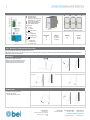
FIG.1 - CONNECTIONS
FIG.2 - DIMENSIONS
FIG.3 - DISTANCES
Just for reference
(1) AC/DC input
(2) DC output (load)
(3) Diagnostic Output
(dry contact, NC output OK)
(Not present on 72 V model)
(4) Green LED: Output OK
(5) Output voltage adjustment
(6) Input Voltage Selector
Input AC Line:
▪ L = Line
▪ N = Neutral
▪ = Earth ground
Input DC Line:
▪ L = + Positive DC
▪ N = - Negative DC
▪ = Earth ground
Output:
▪ + = Positive DC
▪ - = Negative DC
▪ Dry contact = NC
Dimension
W
D
H
mm (inc)
63 (2.48)
117 (4.60)
140 (5.52)
Distance
A
B
mm (inc)
20 (0.8)
50 (2.0)
FIG.4 - MOUNTING / DISMOUNTING INSTRUCTIONS
For DIN rail fastening according to IEC 60715 TH35-7.5(-15)
Mounting as shown in figure, with input terminals on lower side, with suitable cooling and maintaining a proper distance between adjacent devices as specified in the
Installation Instruction of each family.
MOUNTING:
1. Tilt the unit slightly backwards.
2. Fit the unit over the top edge of the rail.
3. Slide it downward until it hits the stop.
4. Press against the bottom for locking.
1
2
3
4
DISMOUNTING:
1. Pull down the slide clamp lever
2. Tilt the unit upward
3. Unhook the unit from the rail
1 & 2
3

Manufacturer
Bel Fuse Inc.
300 Executive Drive, Suite 300
West Orange, NJ 07052
USA
Asia-Pacific
+86 755 2988 5888
Europe, Middle East
+353 61 49 8941
North America
+1 866 513 2839
belfuse.com/power-solutions
© 2023 Bel Fuse Inc.
BCM.00403_AF
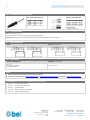
FIG.5 - RECOMMENDED CONNECTING CABLE
Recommended Tightening torque
MFG
Nm
Ibf in
Dinkle
0.51
4.5
ULO
0.51
4.5
Anytek
0.57
5
Würth
0.57
5
Cable Size (Solid & Stranded)
MFG
mm2
AWG
Dinkle
2.5 - 0.20
12 - 28
ULO
2.5 - 0.20
12 - 28
Anytek
2.5 - 0.34
12 - 24
Würth
3.3 - 0.20
12 - 24
Stripping Length
7 – 8 mm / 0.28 – 0.32 in
FIG.6 - INPUT PROTECTION
Fuse 10AT or MCB 10 A C curve.
For USA and Canada, use the fuse type closest to the European equivalent type.
Surge protection: it is strongly recommended to provide external surge arresters (SPD) according to local regulations.
FIG.7 - INPUT CONNECTIONS
AC LINE
DC LINE (UL not evaluated)
FIG.8 - ENVIRONMENT
OPERATING TEMPERATURE
DERATING (UL not evaluated)
- 40°C - 70°C
5 - 95% r.H. non condensing
UL Certified up to 2000 m
- 5 W / °C over 50°C
NOTES:
▪ Data may change without prior notice in order to improve the product.
▪ Please refer to the latest version of LDN240 Series Datasheet or LDN240 Series Installation Instruction on our website:
belfuse.com/power-solutions
ACCESSORIES that can be used with LDN240 units (UL not evaluated)
▪ LDX-D50 50 A Active ORing controller
▪ LDX-U20 20 A High performance DC UPS
▪ LDX-B20 150J Buffer Module
▪ LDX-C120 Battery charger and DC UPS Module
▪ LDX-L30 Sealed Lead acid Battery pack
-
 1
1
-
 2
2
-
 3
3
-
 4
4


in anderen Sprachen
- English: BEL LDN240 Installation guide
- français: BEL LDN240 Guide d'installation
- italiano: BEL LDN240 Guida d'installazione
Verwandte Artikel
-
BEL LDB120 - DIN Rail Battery Charger / DC UPS Installationsanleitung
-
-
-
-
-
-
-
-
BEL LDX-SC12 Installationsanleitung
-