
1
Kurzanleitung/Quickstart
DE EN
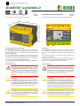
Insulation monitoring device
This quickstart guide does not replace the operating manual.
Intended use
The ISOMETER® isoNAV685-D monitors the insulation resistance
of unearthed AC main circuits (IT systems) with input voltages of
AC 0…690 V and a frequency of 60 Hz in the three-phase net-
work.
DC components existing in AC/DC systems do not influence the
operating characteristics.
Due to the separate supply voltage, de-energised systems can
also be monitored. The maximum permissible system leakage ca-
pacitance is 0…150 µF, depending on the profile.
Safety instructions
Risk of electric shock!
The terminals carry high voltage and direct contact with
these terminals will likely result in electrocution. If the
terminals L1/+, L2, L3/- of the device are connected to a
live IT system, the terminals E and KE must not be discon-
nected from the protective conductor (PE).
Risk of damage to property due to incorrect
installation!
There should only be one insulation monitoring device
per conductively connected installation. Damage to the
installation may result if several insulation monitoring
devices are connected. In addition, the device will not
function and will not report an insulation fault if more
than one insulation monitoring device is connected.
Disconnect from the IT system!
The insulation monitoring device must be disconnected
from the IT system before insulation or voltage tests at
the installation and must remain so for the duration of
the test. Otherwise the device may be damaged.
DANGER
CAUTION
CAUTION
Isolationsüberwachungsgerät
Diese Kurzanleitung ersetzt nicht das Handbuch.
Bestimmungsgemäße Verwendung
Das ISOMETER® isoNAV685-D überwacht den Isolationswider-
stand von ungeerdeten AC-Hauptstromkreisen (IT-Systemen) mit
Netzspannungen von AC 0…690 V und einer Frequenz von 60 Hz
im dreiphasigen Netz.
Die in AC/DC-Systemen vorhandenen gleichstromgespeisten
Komponenten haben keinen Einfluss auf das Ansprechverhalten.
Durch die separate Versorgungsspannung ist auch die Überwa-
chung eines spannungslosen Systems möglich.
Die maximal zulässige Netzableitkapazität beträgt, profilabhän-
gig, 0…150 F.
Sicherheitshinweise
Gefahr eines elektrischen Schlages!
An den Klemmen liegt eine hohe Spannung an, die bei
direkter Berührung lebensgefährlich ist. Ist das Gerät mit
den Klemmen L1/+, L2, L3/- an ein betriebsbedingt span-
nungsführendes IT-System angeschlossen, dürfen die
Klemmen KE und E nicht vom Schutzleiter (PE) getrennt
werden.
Gefahr von Sachschaden durch unsachgemäße
Installation!
Die Anlage kann Schaden nehmen, wenn Sie mehr als
ein Isolationsüberwachungsgerät anschließen. Sind me-
hrere Geräte angeschlossen, funktioniert das Gerät nicht
und meldet keine Isolationsfehler. Schließen Sie in jedem
leitend verbundenen System nur ein ISOMETER® an.
Trennung vom IT-System beachten!
Bei Isolations- und Spannungsprüfungen an der Anlage
muss das Isolationsüberwachungsgerät für die Dauer
der Prüfung vom IT-System getrennt sein. Andernfalls
kann das Gerät Schaden nehmen.
108 mm
110 mm
m
m
39
IT System
3x
230 kΩ
1/4
230 kΩ
GEFAHR
VORSICHT
VORSICHT
ISOMETER® isoNAV685-D
isoNAV685-D_D00215_02_Q_DEEN/04.2017
DE EN

2
isoNAV685-D_D00215_02_Q_DEEN/04.2017
ISOMETER® isoNAV685-D
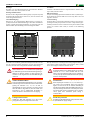
Installation
Consider a minimum distance to adjacent devices: lateral 0 mm,
top 20 mm, bottom 20 mm!
DIN rail mounting:
Snap all 3 mounting clips delivered with the device (2 of them pa-
cked separately) onto the DIN rail in such a way that a safe and
tight fit is ensured.
Screw mounting
Install the three accompanying mounting clips (2 are packed se-
parately) manually or by means of a tool in a way that they pro-
trude beyond the enclosure. Fix the device by means of three M4
screws (no counter sunk screw) as shown in the following
pictures.
Connection
Wire up the device according to the wiring diagram taking ac-
count of the technical data. After connecting the device, install
the enclosed upper and lower terminal cover!
Risk of electric shock!
A nominal voltage of up to 1000 V may be present at the
terminals L1/+…L3/–. Direct contact with these will
likely result in electrocution. Make sure the terminal co-
vers are properly mounted and clicked in before putting
the device into operation.
Danger of injury, fire and damage to property due to
a short circuit!
When coupling the terminals L1/+, L2, L3/- to the IT sys-
tem ≤690 V to be monitored, devices for protection
against a short-circuit can be omitted according to
IEC 60364-4-43:2008 or DIN VDE 0100430 (German ver-
sion) if the wiring is carried out in such a way as to reduce
the risk of a short-circuit to a minimum. The use of short-
circuit proof and earth-fault proof wiring is
recommended.
Provide line protection!
According to DIN VDE 0100-430, a line protection shall
be provided for the supply voltage.
DANGER
WARNING
VORSICHT
Montage
Beachten Sie den Mindestabstand zu benachbarten Geräten:
seitlich 0 mm, oben 20 mm, unten 20 mm!
Montage auf Hutschiene
Rasten Sie alle 3 mitgelieferten Montageclips (2 separat verpackt)
des Geräts auf der Hutschiene unten so ein, dass ein sicherer und
fester Sitz gewährleistet ist.
Schraubbefestigung
Bringen Sie die 3 mitgelieferten Montageclips (2 separat ver-
packt) manuell oder mittels Werkzeug in eine über das Gehäuse
hinaus ragende Rastposition. Befestigen Sie das Gerät mit drei
M4-Schrauben (kein Senkkopf), siehe nachfolgende Skizze.
Anschluss
Verdrahten Sie das Gerät gemäß Anschlussplan. Beachten Sie da-
bei die technischen Daten. Montieren Sie nach dem Anschluss
die obere und die untere mitgelieferte Klemmenabdeckung!
Gefahr eines elektrischen Schlages!
An den Klemmen L1/+…L3/- können Nennspannungen
bis 1000 V anliegen, die bei direkter Berührung lebensge-
fährlich sein können. Nehmen Sie das Gerät nur mit
montierten und eingerasteten Klemmenabdeckungen
in Betrieb.
Gefahr von Verletzungen, Bränden und Sach-
schäden durch Kurzschluss!
Entsprechend DIN VDE 0100-430 können Sie auf Schut-
zeinrichtungen zum Schutz bei Kurzschluss für die Anko-
pplung der Klemmen L1/+, L2, L3/- an das zu
überwachende IT-System verzichten, wenn die Leitung
oder das Kabel so ausgeführt ist, dass die Gefahr eines
Kurzschlusses auf ein Mindestmaß beschränkt ist.
Achten Sie auf kurz- und erdschlussfeste Verlegung.
Leitungsschutz vorsehen!
Gemäß der DIN VDE 0100-430 ist bei der Versor-
gungsspannung ein Leitungsschutz vorzusehen.
Screw mounting
DIN rail mounting
72 mm
108 mm
54 mm
100 mm
107,3 mm
GEFAHR
WARNUNG
VORSICHT

3
isoNAV685-D_D00215_02_Q_DEEN/04.2017
ISOMETER® isoNAV685-D
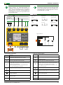
Wiring diagram
Legend to terminal diagram
Connection to X1:
External Power supply for powering iso685 via terminal
X1 must fulfil immunity and emission standards of the
required application. For wiring longer than 1 m the use
of a shielded cable is prescribed.
Terminal Connections
I1…I3
(X1)
Configurable digital inputs (e.g. Test, Reset).
A, B
(X1)
Serial interface RS-485
termination by means of a DIP switch R (OFF, ON).
+
(X1)
• Supply voltage of the inputs and outputs I, Q and M.
• Electrical overload protection. Automatic shutdown in the
event of a short circuit and transient (resettable).
• If the supply is via an external 24 V source, then A1/+, A2/-
must not be connected.
Q1, Q2
(X1)
Configurable digital output
M+
(X1)
Configurable analogue output (e.g. measuring instrument)
(X1)
Reference potential ground
RJ45
(ETH)
Ethernet connection
R Switchable terminating resistor
Anschlussplan
Legende zum Anschlussplan
Anschluss an X1:
Externe Netzteile, zur Spannungsversorgung des
ISOMETER®s über die Klemme X1, müssen den Störfesti-
gkeits- und Emissionsanforderungen der geforderten
Applikationsnorm entsprechen. Für Verbindungsleitun-
gen, die länger als 1 m sind, müssen geschirmte Leitun-
gen verwendet werden.
Klemme
Anschlüsse
I1…I3
(X1)
Konfigurierbare digitale Eingänge (z. B. Test, Reset).
A, B
(X1)
Serielle Schnittstelle RS-485,
Terminierung mittels DIP-Schalter R (OFF, ON).
+
(X1)
• Versorgungsspannung der Ein- und Ausgänge I, Q und M.
• Elektr. Überlastschutz. Autom. Abschaltung bei Kurzschluss
und Transiente (rücksetzbar).
• Bei Versorgung über ein externes 24-V-Netzteil dürfen
A1/+,A2/- nicht angeschlossen werden.
Q1, Q2
(X1)
Konfigurierbarer digitaler Ausgang
M+
(X1)
Konfigurierbarer analoger Ausgang (z. B. Messinstrument)
(X1)
Bezugspotential Masse
RJ45
(ETH)
Ethernet-Anschluss
R Zuschaltbarer Abschlusswiderstand
I1
I2
I3
A
B
M+
Q2
Q1
+
Wiring example X1
Q
x
X1
+
Q
x
X1
+I
X1
+I
x
X1
M
+
X1 X1
A
M
+
X1 X1
V
Passive
Active
Active high
x
Active low
Current output
Voltage output
X1
X1 X1
X1
Digital outputs
Digital inputs
Analogue output
L1
L2
L3
N
PE
U
S
A1/+ A2/-
11RETHX1 12 14 21 22 24
L1/+
L2 L3/- KE E
87
3(N)AC
I1 I2 I3 A B
Q1
+
Q2 M+
X1
Data-isoGraph 2
1/3
Stunde 16:52
Data-isoGraph 2
1/4
1,0
,10 0
,010
,001
MΩ
Stunde 16:26 16:52

4
isoNAV685-D_D00215_02_Q_DEEN/04.2017
ISOMETER® isoNAV685-D
Inbetriebnahme
Inbetriebnahmeschema
Inbetriebnahme
1. Prüfen Sie den korrekten Anschluss des ISOMETER®s an das
zu überwachende Netz.
2. Schalten Sie die Versorgungsspannung für das ISOMETER®
zu.
3. Schalten Sie die Netzspannung zu.
4. Das Gerät führt einen vierstufigen Selbsttest durch, die
Alarmrelais werden dabei nicht geprüft. Danach erscheint im
Display der ermittelte Isolationswiderstand. Liegt er über
den in der untersten Zeile eingeblendeten Ansprechwerten,
wird zusätzlich die Meldung „OK“ angezeigt. Wird während
des Selbsttests ein Fehler erkannt, erscheint im Display eine
Fehlermeldung.
5. Funktion mit einem echten Isolationsfehler prüfen. Das
ISOMETER® ist am überwachten Netz z. B. mit einem dafür
geeigneten Widerstand gegen Erde zu prüfen.
Alarm und seine Wirkung
Ursachen für eine Alarmmeldung
• Isolationsfehler
– Der gemessene Isolationswiderstand unterschreitet
den Ansprechwert.
– LED ALARM 1 leuchtet.
• Isolationsfehler + DC-Verlagerungsspannungsfehler
– Der gemessene Isolationswiderstand unterschreitet
den Ansprechwert und die DC-Verlagerungsspannung
überschreitet den Ansprechwert.
– LED ALARM 2 leuchtet.
• Gerätefehler
– Interner Gerätefehler.
– LED SERVICE leuchtet.
Das Profil „Leistungskreise“ ist für die meisten IT-Systeme
geeignet. Eine Beschreibung der Profile finden Sie im
Handbuch.
Inbetriebnahme ISOMETER
®
Ggf. Grundeinstellungen
anpassen
Gerät anschließen gemäß
Anschlussplan
Versorgungsspannung zuschalten
Netzspannung zuschalten
Das ISOMETER
®
führt einen
Selbsttest durch
Funktionsprüfung mit geeignetem
Widerstand von Netz nach Erde,
Größe: 50% des Ansprechwertes
Alarm2
Widerstand entfernen
Das ISOMETER
®
ist
funktionstüchtig und richtig
angeschlossen
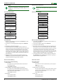
Commissioning of the device
Commissioning scheme
General commissioning process
1. Check that the ISOMETER® is properly connected to the sys-
tem to be monitored.
2. Connect the supply voltage to the ISOMETER®.
3. Connect the mains voltage.
4. The device carries out a self test in four steps. However, the
alarm relays are not checked during this test. After comple-
tion of the test, the measured insulation resistance is shown
on the display. If the value exceeds the response values
indicated in the lowest line of the display, the message "OK"
will additionally be displayed. If a fault is detected during the
self test, a fault message will appear on the display.
5. Check the function using a genuine insulation fault. Check
the ISOMETER® in the system being monitored, e.g. using a
suitable resistance against earth.
Alarm and its effect
Cause of the alarm
• Insulation fault
– The insulation resistance falls below a preset response
value.
– LED ALARM 1 flashes.
• Insulation fault + DC offset fault
– The measured insulation resistance falls below a preset
response value and the DC residual voltage is higher
than a preset response value.
– LED ALARM 2 flashes.
• Device error
– Internal device error.
– LED SERVICE flashes.
The profile "power circuits" is suitable for most of the IT
systems. For a description of the profiles refer to the
manual.
Commissioning the ISOMETER®
Adjust basic settings if
necessary
Install the device according to the
wiring diagram
and documentation
Connect the supply voltage
Connect the system voltage
The ISOMETER® performs a self
test
Function test with a suitable
resistance between system and
earth. Resistance value: 50% of
the response value Alarm 2
Remove the resistance
The ISOMETER® is properly
connected and
functions reliably
Run the commissioning
wizard

5
isoNAV685-D_D00215_02_Q_DEEN/04.2017
ISOMETER® isoNAV685-D
Gerät meldet Alarm bzw. Gerätefehler
• Display zeigt Fehler und ggf. Messwert an.
• Bei Isolationsfehler, DC-Verlagerungsspannungsfehler und
Gerätefehler leuchten die zugehörigen LEDs.
• Alarmton ertönt intervallweise, wenn zugeordnet.
• Zugeordnete Alarmrelais schalten.
• Zugeordnete digitale Ausgänge schalten.
Alarmmeldungen zurücksetzen (Reset)
Voraussetzung: Ursache für Alarmmeldung besteht nicht mehr.
Isolationswiderstand muss mindestens 25 % über dem Ansprech-
wert liegen.
Wählen Sie: „RESET“ > „RESET“ > „OK“.
Werkseinstellungen
Ansprechwerte
Ansprechwert R
an
(Alarm 1)
5 k
Ansprechwert DC-Verlagerungsspannung
(Alarm 2)
150 V
Anlaufverzögerung T
Anlauf
0 s
Schnittstellen
IP-Adresse manuell 192.168.0.5
Netzmaske 255.255.255.0
BCOM-Adresse system-1-0
Digitale Eingänge
Arbeitsweise
X1.I1 & X1.I3:
high-aktiv
Funktionen
X1.I1: Reset;
X1.I3: Gerät deaktivie-
ren
Digitale Ausgänge
Funktionen
X1.Q1: Isolationsfehler
+ DC-Verlagerungs-
spannung
Schaltglieder
Arbeitsweise Ruhestrom (N/C)
Kontakt 11-12-14
Funktion 1: Iso. Alarm 1
Kontakt 21-22-24
Funktion 1: Isolations-
fehler + DC-Verlage-
rungsspannung
Sonstiges
Netzform 3 AC
Sprache Deutsch
Ankoppelüberwachung ein
Fehlerspeicher ein
Profil Leistungskreise
Device signals alarm or device error
• The display indicates an error and, where applicable, the
measured value.
• In the event of "ALARM 1" or "ALARM 2", the associated LEDs
flash.
• A warning sound beeps at certain intervals, if assigned
accordingly.
• Assigned alarm relays will switch.
• Assigned digital outputs will switch.
Reset alarm messages (Reset)
Requirement: The cause of the alarm is no longer present.
The insulation resistance must be at least 25 % higher than the
response value.
Select: "RESET" > "RESET" > "OK".
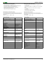
Factory settings
Response values
Response value R
an
(Alarm 1)
5 k
Response value DC residual voltage
(Alarm 2)
150 V
Start-up delay T
Anlauf
0 s
Interfaces
IP-Adresse manual 192.168.0.5
Network mask 255.255.255.0
BCOMAddress system-1-0
Digital Inputs
Mode
X1.I1 & X1.I3:
active high
Functions
X1.I1: Reset;
X1.I3: Deactivate device
Digital Outputs
Functions
X1.Q1: Insulation fault
+ DC offset fault
Switching elements
Operating principle NC operation
Contact 11-12-14
Function 1:
Insulation Alarm 1
Contact 21-22-24
Function 1:
Insulation fault +
DC offset fault
Other
Power supply system 3 AC
Language German
Coupling monitoring on
Fault memory on
Profile Power circuits

6
isoNAV685-D_D00215_02_Q_DEEN/04.2017
ISOMETER® isoNAV685-D
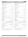
Technische Daten
Isolationskoordination (IEC 60664-1/IEC 60664-3)
Bemessungsspannung...............................................................................................................................1000 V
Überspannungskategorie (OVC).........................................................................................................................III
Bemessungs-Stoßspannung (IEC 60664-1) ................................................................................................ 8 kV
Bemessungsisolationsspannung (IEC 60664-1) ..................................................................................... 1000 V
Verschmutzungsgrad (U
n
< 690 V) .................................................................................................................. 3
Verschmutzungsgrad (U
n
< 1000 V) ................................................................................................................ 2
Sichere Trennung (≤ 2000 m NN) zwischen ........................................................................ (L1/+,L2,L3/-) –
...............................................................................(A1,A2) – (11,12,14) – (21,22,24) – (E, KE), (X1, ETH, X3)
Spannungsprüfung, Stückprüfung (IEC 61010-1) .............................................................................. AC 2,2 kV
Versorgungsspannung
Versorgung über A1/+,A2/-:
Versorgungsspannungsbereich U
s
....................................................................................... AC/DC 24…240 V
Toleranz von U
s
............................................................................................................................. -30…+15 %
Frequenzbereich von U
s
........................................................................................................... DC, 50…400 Hz
Leistungsaufnahme typ. 50/60 Hz (400 Hz).....................................................≤12 W/21 VA (≤12 W/45 VA)
Versorgung über X1:
Versorgungsspannung U
s
.........................................................................................................................DC 24 V
Toleranz von U
s
........................................................................................................................ DC -20…+25 %
Überwachtes IT-System
Netznennspannungsbereich U
n
................................................................................................... AC 0…690 V
..................................................................................................................AC 0…600 V (für UL Anwendungen)
Toleranz von U
n
.................................................................................................................................... AC +15 %
Frequenzbereich von U
n
.............................................................................................................................. 60 Hz
Ansprechwerte
Ansprechwert R
an1
(Alarm 1) ...................................................................................................... 1 kΩ…10 MΩ
Ansprechwert R
an2
(Alarm 2) ......................................................................................................... 20 V…1 kV
Ansprechunsicherheit (nach IEC 61557-8).............................................profilabhängig, ±15 %, mind. ±1 kΩ
Zeitverhalten
Ansprechzeit tan bei DC-Verlagerungsspannung > 1,1x U
DC
und Alarm 1 ..............................max. 150 ms
(1
Ansprechzeit tan bei R
F
= 0,5 x R
an
(R
an
= 10 kΩ) und C
e
= 1 μF nach IEC 61557-8........................................
..................................................................................profilabhängig, typ. 4 s (siehe Diagramme im Handbuch)
Schnittstellen
Feldbus: Schnittstelle/Protokoll.........................................................................Webserver/Modbus TCP/BCOM
Feldbus: Funktion.................................................................................................. Kommunikationsschnittstelle
Schaltglieder
Schaltglieder ....................................................................................................................................... 2 Wechsler
Arbeitsweise ......................................................................................... Ruhestrom (N/C) / Arbeitsstrom (N/O)
Kontakt 11-12-14 .....................................Keine, Iso. Alarm 1, Isolationsfehler + DC-Verlagerungsspannung,
................................................Anschlussfehler , Gerätefehler, Sammelalarm, Messung beendet, Gerät inaktiv
Kontakt 21-22-24 .....................................Keine, Iso. Alarm 1, Isolationsfehler + DC-Verlagerungsspannung,
................................................Anschlussfehler , Gerätefehler, Sammelalarm, Messung beendet, Gerät inaktiv
Elektrische Lebensdauer bei Bemessungsbedingungen...................................................... 10.000 Schaltspiele
Kontaktdaten nach IEC 60947-5-1
Gebrauchskategorie ............................................................................. AC-13 /AC-14 / DC-12 / DC-12 / DC-12
Bemessungsbetriebsspg. ......................................................................... 230 V / 230 V / 24 V / 110 V / 220 V
Bemessungsbetriebsstrom .................................................................................... 5 A / 3A / 1 A / 0,2 A / 0,1 A
Bemessungsisolationsspannung ≤2000 m NN ......................................................................................... 250 V
Bemessungsisolationsspannung ≤3000 m NN ......................................................................................... 160 V
Minimale Kontaktbelastbarkeit ..................................................................................... 1 mA bei AC/DC ≥10 V
Sonstiges
EMV ........................................................................................................................................... IEC 61326-2-4
(2
Schutzart Einbauten ..................................................................................................................................... IP40
Schutzart Klemmen ....................................................................................................................................... IP20
1)
Die Schnellauslösung funktioniert nur in IT-Netzen mit einer Netzfrequenz von 60 Hz.
2)
Dies ist eine Einrichtung der Klasse A. Diese Einrichtung kann im Wohnbereich Funkstörungen verursachen.
In diesem Fall kann vom Betreiber verlangt werden, angemessene Maßnahmen durchzuführen.
Technical data
Insulation co-ordination (IEC 60664-1/IEC 60664-3)
Rated voltage ............................................................................................................................................. 1000 V
Overvoltage category (OVC) ...............................................................................................................................III
Rated impulse voltage (IEC 60664-1) .......................................................................................................... 8 kV
Rated insulation voltage (IEC 60664-1) ................................................................................................... 1000 V
Pollution degree (U
n
< 690 V) .......................................................................................................................... 3
Pollution degree (U
n
< 1000 V) ........................................................................................................................ 2
Protective separation (≤ 2000 m NN) between......................................................................(L1/+,L2,L3/-) –
........................................................................ (A1,A2) – (11,12,14) – (21,22,24) – (E, KE), (X1, ETH, X3, X4)
Voltage test, routine test (IEC 61010-1) ............................................................................................. AC 2.2 kV
Supply voltage
Supply via A1/+,A2/-:
Supply voltage range U
s
....................................................................................................... AC/DC 24…240 V
Tolerance of U
s
............................................................................................................................. -30…+15 %
Frequency range of U
s
............................................................................................................. DC, 50…400 Hz
Power consumption typ. 50/60 Hz (400 Hz)...................................................≤12 W/21 VA (≤12 W/45 VA)
Supply via X1:
Supply voltage U
s
......................................................................................................................................DC 24 V
Tolerance of U
s
......................................................................................................................... DC -20…+25 %
IT system being monitored
Nominal system voltage range U
n
..................................................................................................AC 0…690 V
..................................................................................................................... .AC 0…600 V (for UL applications)
Tolerance of U
n
.................................................................................................................................... AC +15 %
Frequency range of U
n
..................................................................................................................................60 Hz
Response values
Response value R
an1
(Alarm 1) .................................................................................................... 1 kΩ…10 MΩ
Response value R
an2
(Alarm 2) ........................................................................................................ 20 V…1 kV
Operating uncertainty (acc. to IEC 61557-8)...................................profile dependent, ±15 %, at least ±1 kΩ
Time response
Response time tan for DC residual voltage > 1.1 x
U
DC
and Alarm 1 ............................................max. 150 ms
(1
Response time tan at
R
F
= 0.5 x
R
an
(
R
an
= 10 kΩ) and
C
e
= 1 μF acc. to IEC 61557-8 ........................................
............................................................................................. profile dependent, typ. 4 s (see diagrams in manual)
Interfaces
Field bus: Interface/protocol............................................................................. Webserver/Modbus TCP/BCOM
Field bus: Function....................................................................................................... communication interface
Switching elements
Switching elements......................................................................................................... 2 changeover contacts
Operating principle ................................................................................................N/C operation/N/O operation
Contact 11-12-14 ..........................................none, insulation Alarm 1, insulation fault + DC residual voltage
......................................Connection fault, device fault, collective alarm, measurement ended, device inactive
Contact 21-22-24 .......................................Nnone, insulation Alarm 1, insulation fault + DC residual voltage
......................................Connection fault, device fault, collective alarm, measurement ended, device inactive
Electrical endurance under rated operating conditions ............................................................... 10,000 cycles
Contact data acc. to IEC 60947-5-1
Utilisation category................................................................................AC-13...AC-14...DC-12...DC-12...DC-12
Rated operational voltage. ......................................................................... 230 V...230 V...24 V...110 V...220 V
Rated operational current....................................................................................... 5 A...3 A...1 A...0.2 A...0.1 A
Rated insulation voltage ≤2000 m NN .......................................................................................................250 V
Rated insulation voltage ≤3000 m NN .......................................................................................................160 V
Minimum contact rating.................................................................................................. 1 mA at AC/DC ≥ 10 V
Other
EMC .............................................................................................. IEC 61326-2-4; EN50121-3-2; EN50121-4
(2
Degree of protection, built-in components (DIN EN 60529) ....................................................................... IP40
Degree of protection, terminals (DIN EN 60529) ......................................................................................... IP20
1)
Fast tripping only works in IT networks with a mains frequency of 60 Hz.
2)
This is a class A product. In a domestic environment this product may cause radio interference in which case
the user may be required to take adequate measures.

7
isoNAV685-D_D00215_02_Q_DEEN/04.2017
ISOMETER® isoNAV685-D

8
isoNAV685-D_D00215_02_Q_DEEN/04.2017
ISOMETER® isoNAV685-D
Alle Rechte vorbehalten.
Nachdruck und Vervielfältigung
nur mit Genehmigung des Herausgebers.
Änderungen vorbehalten!
© Bender GmbH & Co. KG
All rights reserved.
Reprinting and duplicating
only with permission of the publisher.
Subject to change!
© Bender GmbH & Co. KG
Service
Service hotline: 0700-BenderHelp (Telephone and Fax)
Carl-Benz-Straße 8 • 35305 Gruenberg • Germany
Tel: +49 6401-807-760 • Fax: +49 6401 807-629
E mail: [email protected] • www.bender.de
Bender GmbH & Co. KG
Postfach 1161 • 35301 Gruenberg • Germany
Londorfer Str. 65 • 35305 Gruenberg • Germany
Tel.: +49 6401-807-0 • Fax: +49 6401 807-259
E mail: [email protected] • www.bender.de
Documentation
-
 1
1
-
 2
2
-
 3
3
-
 4
4
-
 5
5
-
 6
6
-
 7
7
-
 8
8


Bender ISOMETER isoNAV685-D Schnellstartanleitung
- Typ
- Schnellstartanleitung
- Dieses Handbuch ist auch geeignet für
in anderen Sprachen
Verwandte Papiere

Sonstige Unterlagen
-
DeWalt PE242SHI011 Benutzerhandbuch
-
PILZ S1MS Ex Operating Instructions Manual
-
ABB CM-IWN.1 Insulation monitoring relay Bedienungsanleitung
-
INOTEC CPS 220/64/J-SV Mounting And Operating Instructions
-
ASO Safety Solutions ELMON relay 41-312 / 41-812 Bedienungsanleitung
-
-
Eaton EMR4-RAC-1-A Bedienungsanleitung
-
-
Fronius Symo Benutzerhandbuch