
SERIE Z
MANUALE D’INSTALLAZIONE
ZA4N
QUADRO COMANDO
PER MOTORIDUTTORI A 230V
Ita
li
ano
I
T
9

Pag.
2
2 - Codice manuale:
319V08
319V08 ver.
1.0
1.0 05/2009 © CAME cancelli automatici s.p.a. - I dati e le informazioni indicate in questo manuale sono da ritenersi suscettibili di modifica in qualsiasi momento e senza obbligo di preavviso da parte di CAME cancelli automatici s.p.a.
ITALIANO
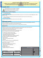
La potenza complessiva dei motori collegati non deve superare i 600W.
4 Descrizione
2.1 Destinazione d’uso
1 Legenda simboli
Questo simbolo indica parti da leggere con attenzione.
Questo simbolo indica parti riguardanti la sicurezza.
Questo simbolo indica cosa comunicare all’utente.
2 Destinazione e ambiti d’impiego
Il quadro comando ZA4N è stato progettato per il comando delle automazioni per cancelli a battente ATI, FERNI, KRONO, FAST e FROG
alimentati a 230V.
Ogni installazione e uso difformi da quanto indicato nel seguente manuale sono da considerarsi vietate.
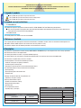
3 Riferimenti normativi
“IMPORTANTI ISTRUZIONI DI SICUREZZA PER L’INSTALLAZIONE”
“ATTENZIONE: L’INSTALLAZIONE NON CORRETTA PUÓ CAUSARE GRAVI DANNI, SEGUIRE TUTTE LE ISTRUZIONI DI INSTALLAZIONE”
“IL PRESENTE MANUALE É DESTINATO ESCLUSIVAMENTE A INSTALLATORI PROFESSIONALI O A PERSONE COMPETENTI”
2.2 Ambiti d’impiego
Came Cancelli Automatici è un’azienda certificata per il sistema di gestione della qualità aziendale ISO 9001 e di gestione
ambientale ISO 14001. Came progetta e produce interamente in Italia.
Il prodotto in oggetto è conforme alle seguenti normative: vedi dichiarazione di conformità.
Progettato e costruito interamente dalla CAME Cancelli Automatici S.p.A. Garantito 24 mesi salvo manomissioni.
Il quadro comando va alimentato a 230V A.C., con frequenza max 50/60Hz.
I dispositivi di comando e gli accessori sono a 24V.
Attenzione! Gli accessori non devono superare complessivamente i 20W.
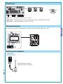
Tutte le connessioni sono protette da fusibili rapidi, vedi tabella.
La scheda eroga e controlla le seguenti funzioni:
- chiusura automatica dopo un comando di apertura;
- prelampeggio dell’indicatore di movimento;
- regolazione della coppia motrice dell’automazione collegata.
Le modalità di comando che è possibile defi nire sono:
- apertura/chiusura;
- apertura/chiusura ad azione mantenuta;
- stop totale.
Le fotocellule, dopo la rilevazione di un ostacolo, provocano:
- la riapertura se il cancello sta chiudendo;
Appositi trimmers regolano:
- il tempo di intervento della chiusura automatica;
- ritardo chiusura del motoriduttore M2;
- il tempo di lavoro.
È possibile collegare anche:
- lampada di segnalazione cancello aperto.
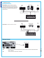
TABELLA FUSIBILI
a protezione di: fusibile da:
Scheda elettronica (linea) 5A-F
Dispositivi di comando e
accessori (centralina) 1A-F
DATI TECNICI
tensione di alimentazione 230V - 50/60Hz
potenza massima ammessa 600W
potenza massima per accessori a 24V 20W
classe di isolamento dei circuiti
materiale del contenitore ABS
grado di protezione del contenitore IP54
temperatura di esercizio -20 / +55°C

F U SI B I LI LI N E A 5 A
QUADRO C OMANDO
ZA4
FUSIBILE CEN TRALINA 1A
T. L.
T. C . A .
TR2M .
1 2
L1 L2 UVWXYE1 10 11 1 5 7 C1
23
L1 L2 C 24120
L2T L1T1234
012 24
1
48
2
3
9
10 5 6 7
11
Pag.
3
3 - Codice manuale:
319V08
319V08 ver.
1.0
1.0 05/2009 © CAME cancelli automatici s.p.a. - I dati e le informazioni indicate in questo manuale sono da ritenersi suscettibili di modifica in qualsiasi momento e senza obbligo di preavviso da parte di CAME cancelli automatici s.p.a.
ITALIANO
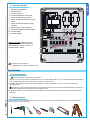
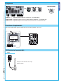
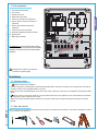
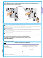
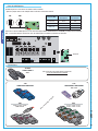
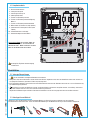
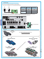
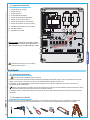
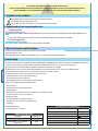
4.1 Componenti principali
Attenzione! Prima di intervenire
sull’apparecchiatura, togliere la tensione di linea.
1 - Morsettiere di collegamento
2 - Fusibili di linea 5A
3 - Fusibile centralina 1A
4 - Pulsante memorizzazione codice radio
5 - Trimmer di regolazione tempo lavoro
6 - Trimmer di regolazione ritardo in chiusura 2°
motore
7 - Trimmer di regolazione tempo in chiusura
automatica
8 - Selettore funzioni a 2 dip (vedi pag.6)
9 - Innesto scheda radiofrequenza (vedi tabella)
10 - LED segnalazione
11 - Limitatore di coppia
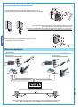
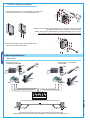
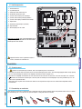
Nota per serie FROG: collegare i fi li neri che
fuoriescono dalla scheda sui connettori del
condensatore del 1° motore e i fi li rossi sul
condensatore del 2° motore.
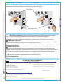
Prima di procedere all’installazione è necessario:
• Verificare che il punto di fissaggio del quadro elettrico sia in una zona protetta dagli urti, che le superfici di ancoraggio siano solide, e
che il fissaggio venga fatto con elementi idonei (viti, tasselli, ecc) alla superficie.
• Prevedere adeguato dispositivo di disconnesione onnipolare, con distanza maggiore di 3 mm tra i contatti, a sezionamento
dell’alimentazione
• Verifi care che le eventuali connessioni interne al contenitore (eseguite per la continuità del circuito di protezione) siano provviste
di isolamento supplementare rispetto ad altre parti conduttrici interne.
• Predisporre tubazioni e canaline adeguate per il passaggio dei cavi elettrici garantendone la protezione contro il danneggiamento
meccanico.
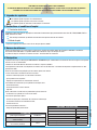
Assicurarsi di avere tutti gli strumenti ed il materiale necessario, per effettuare l’installazione nella massima sicurezza, secondo le
normative vigenti. Ecco alcuni esempi.
5 Installazione
5.1 Verifiche preliminari
5.2 Attrezzi e materiali

UVWXYE1
FROG
FERNI
KRONO
FROG
FERNI
KRONO
FAST
ATI
ATI
M1 M2
FAST
Pag.
4
4 - Codice manuale:
319V08
319V08 ver.
1.0
1.0 05/2009 © CAME cancelli automatici s.p.a. - I dati e le informazioni indicate in questo manuale sono da ritenersi suscettibili di modifica in qualsiasi momento e senza obbligo di preavviso da parte di CAME cancelli automatici s.p.a.
ITALIANO
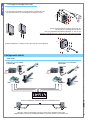
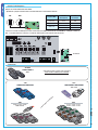
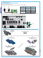
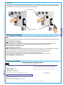
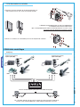
6 Collegamenti elettrici
Nel caso si utilizzi un solo motore (cancello a una sola anta), collegarlo su W X Y (M2)
indipendentemente dal lato di montaggio (per FROG, se necessario, invertire le connessioni X e Y).
Schema predisposizione standard di apertura dei motoriduttori Came.
Motoriduttore ad azione ritardata
in apertura (M1)
Motoriduttore ad azione ritardata in
chiusura (M2)
Motoriduttore
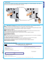
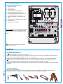
1) Fissare la base del quadro in una zona protetta; si consiglia di usare
viti di diametro max. 6 mm testa bombata con impronta a croce.
5.3 Fissaggio e montaggio della scatola
2) Forare sui fori presfondati e inserire i pressacavi con i
tubi corrugati per il passaggio dei cavi elettrici.
N.B.: i fori presfondati hanno diametri differenti: 23, 29 e 37 mm.
Attenzione a non danneggiare la scheda elettronica all’interno del quadro!!
3) Dopo le regolazioni e i settaggi, fissare il coperchio con le viti in dotazione.

10 11 1 5 7 C1
23
L1 L2 UVWXYE1 10 11 1 5 7 C1
23
10 11L1 L2
Pag.
5
5 - Codice manuale:
319V08
319V08 ver.
1.0
1.0 05/2009 © CAME cancelli automatici s.p.a. - I dati e le informazioni indicate in questo manuale sono da ritenersi suscettibili di modifica in qualsiasi momento e senza obbligo di preavviso da parte di CAME cancelli automatici s.p.a.
ITALIANO
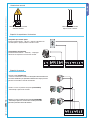
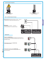
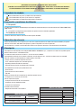
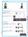
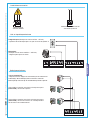
Alimentazione accessori
Alimentazione quadro comando
230V A.C. 50/60 Hz
Morsetti per l’alimentazione
degli accessori a 24V A.C.
Dispositivi di segnalazione e illuminazione
Lampadina spia cancello aperto
(Portata contatto: 24V A.C. - 3W max.) - Segnala la posizione del
cancello aperto, si spegne quando il cancello è chiuso.
Lampeggiatore di movimento
(Portata contatto: 230V A.C. - 25W max.) - Lampeggia
durante le fasi di apertura e chiusura del cancello.
Dispositivi di comando
Pulsante di stop (contatto N.C.)
- Pulsante di arresto del cancello con conseguente esclusione del ciclo
di chiusura automatica, per riprendere il movimento bisogna premere il
pulsante di comando o il tasto del trasmettitore.
Selettore a chiave e/o pulsante di apertura (contatto N.O.)
- Comando per l’apertura del cancello.
Selettore a chiave e/o pulsante per comandi (contatto N.O.)
- Comandi per apertura e chiusura del cancello, premendo il
pulsante o girando la chiave del selettore.

FUSIBILI LINEA 5A
QUADR O CO MAN DO
ZA4
FUSIBILE CENTRALINA 1 A
T. L.
T. C . A .
TR2M.
1 2
L1 L2 UVWXYE1 10 11 1 5 7 C1
23
L1 L2 C 24120
10 11 1 5 7 C1
23
TX
./ # .#
RX
ON
OFF
1 2
10 11 1 5 7 C1
23
TXRX
Pag.
6
6 - Codice manuale:
319V08
319V08 ver.
1.0
1.0 05/2009 © CAME cancelli automatici s.p.a. - I dati e le informazioni indicate in questo manuale sono da ritenersi suscettibili di modifica in qualsiasi momento e senza obbligo di preavviso da parte di CAME cancelli automatici s.p.a.
ITALIANO
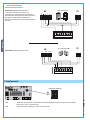
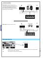
Contatto (N.C.) di «riapertura durante la chiusura»
Fotocellule DOC
7 Selezioni funzioni
DIP-SWITCH 2 VIE
1 ON Funzionamento del cancello mantenendo premuto il pulsante (esclude la funzione del radiocomando) attivato
(1 OFF - disattivato);
2 ON “Chiusura automatica” attivata (2 OFF - disattivata).
Dispositivi di sicurezza
Contatto (N.C.) di «riapertura durante la chiusura»
- Ingresso per dispositivi di sicurezza tipo fotocellule,
bordi sensibili e altri dispositivi conformi alle normative
EN 12978. In fase di chiusura delle ante, l’apertura del
contatto provoca l’inversione del movimento fi no alla
completa apertura.
Fotocellule DIR

FUSIBILI LINEA 5A
QUADR O CO MAN DO
ZA4
FUSIBILE CENTRALINA 1 A
T. L.
T. C . A .
TR2M.
1 2
L1 L2 UVWXYE1 10 11 1 5 7 C1
23
L1 L2 C 24120
T. L.
T. C . A .
TR2M.
1234
L2T
L1T
0
24
12
L1T L2T CT
01224
FUS IBI LI LIN EA 5A
QUADRO COMANDO
ZA4
FUS IBI LE C EN TRA LIN A 1 A
T.L .
T.C . A.
TR2M.
1 2
1234
L2T
L1T
0
24
12
L1TL2T CT
01224
Pag.
7
7 - Codice manuale:
319V08
319V08 ver.
1.0
1.0 05/2009 © CAME cancelli automatici s.p.a. - I dati e le informazioni indicate in questo manuale sono da ritenersi suscettibili di modifica in qualsiasi momento e senza obbligo di preavviso da parte di CAME cancelli automatici s.p.a.
ITALIANO
8 Regolazioni
Trimmer T.L. = Regolazione tempo di lavoro da un minimo di 5” a un massimo di 50”.
Trimmer TR2M = Regolazione ritardo in chiusura 2° motore (M2) da un minimo di 1” a un massimo di 10”.
Trimmer T.C.A. = Regolazione tempo di chiusura automatica da un minimo di 3” a un massimo di 130”.
REGOLAZIONE TRIMMERS
9 Limitatore di coppia motore
Per variare la coppia motore, spostare il faston indicato su una delle 4 posozioni; 1 min, 4 max.
10 Attivazione del comando radio
Collegare il cavo RG58 dell’antenna agli
appositi morsetti.
Antenna

CAME
CAME
TOP
TOP-432A • TOP-434A
TAM
T432 • T434 • T438
TAM-432SA
CAME
CAME
CAME
ATOMO
AT01 • AT02
AT04
CAME
CAME
CAME
CAME
CAME
CAME
CAME
CAME
CAME
TFM
T132 • T134 • T138
T152 • T154 • T158
TOP
TOP-432NA • TOP-434NA
TOP-432S
FUSIBILI LINEA 5A
QUAD RO C OM AN DO
ZA4
FUSIBILE CENTRALINA 1 A
T. L.
T. C . A .
TR2M .
1 2
L1 L2 UVWXYE1 10 11 1 5 7 C1
23
L1 L2 C 24120
TOP TAM
Pag.
8
8 - Codice manuale:
319V08
319V08 ver.
1.0
1.0 05/2009 © CAME cancelli automatici s.p.a. - I dati e le informazioni indicate in questo manuale sono da ritenersi suscettibili di modifica in qualsiasi momento e senza obbligo di preavviso da parte di CAME cancelli automatici s.p.a.
ITALIANO
Trasmettitori
vedi istruzioni su confezione
vedi foglio istruzioni inserito nella confezione
del la scheda di radiofrequenza AF43SR
Innestare la scheda di radiofrequenza sulla scheda elettronica DOPO AVER TOLTO LA TENSIONE (o scollegato le batterie).
N.B.: La scheda elettronica riconosce la scheda di radiofrequenza solo quando viene alimentata.
Scheda di radiofrequenza
Scheda AF
Solo per le schede evidenziate nella tabella:
- posizionare il jumper come illustrato a seconda della serie di trasmettitori utilizzata.
Frequenza/MHz Scheda
radiofrequenza
Serie
trasmettitori
FM 26.995 AF130 TFM
FM 30.900 AF150 TFM
AM 433.92 AF43S/AF43SM TAM/TOP
AF43SR ATOMO

11 Dismissione e smaltimento
12 Dichiarazione di conformità
CAME CANCELLI AUTOMATICI S.p.A. implementa all’interno dei propri stabilimenti un Sistema di Gestione Ambientale
certificato e conforme alla norma UNI EN ISO 14001 a garanzia del rispetto e della tutela dell’ambiente.
Vi chiediamo di continuare l’opera di tutela dell’ambiente, che CAME considera uno dei fondamenti di sviluppo delle proprie strategie
operative e di mercato, semplicemente osservando brevi indicazioni in materia di smaltimento:
SMALTIMENTO DELL’IMBALLO
I componenti dell’imballo (cartone, plastiche etc.) sono assimilabili ai rifiuti solidi urbani e possono essere smaltiti senza alcuna
difficoltà, semplicemente effettuando la raccolta differenziata per il riciclaggio.
Prima di procedere è sempre opportuno verificare le normative specifiche vigenti nel luogo d’installazione.
NON DISPERDERE NELL’AMBIENTE!
SMALTIMENTO DEL PRODOTTO
I nostri prodotti sono realizzati con materiali diversi. La maggior parte di essi (alluminio, plastica, ferro, cavi elettrici) è assimilabile ai
rifiuti solidi e urbani. Possono essere riciclati attraverso la raccolta
e lo smaltimento differenziato nei centri autorizzati.
Altri componenti (schede elettroniche, batterie dei radiocomandi etc.) possono invece contenere sostanze inquinanti.
Vanno quindi rimossi e consegnati a ditte autorizzate al recupero e allo smaltimento degli stessi.
Prima di procedere è sempre opportuno verificare le normative specifiche vigenti nel luogo di smaltimento.
NON DISPERDERE NELL’AMBIENTE!
DICHIARAZIONE DEL FABBRICANTE
Ai sensi dell’Allegato II A della Direttiva 2006/95/CE
I Rappresentanti della
CAME Cancelli Automatici S.p.A.
via Martiri della Libertà, 15
31030Dosson di Casier - Treviso - ITALYtel
(+39) 0422 4940 - fax (+39) 0422 4941
internet: www.came.it - e-mail: [email protected]
Dichiarano sotto la propria responsabilità che i/il prodotto/i denominato/i ...
… sono conformi alle seguenti Direttive Comunitarie:
2006/95/CE - Direttiva Bassa Tensione
2004/108/CE - Direttiva Compatigilità Elettromagnetica
Inoltre, dichiara che il/i prodotto/i, oggetto della presente dichiarazione, sono costruiti
nel rispetto delle seguenti principali norme armonizzate:
EN 60335-1 / EN 60335-2-103 / EN 13241-1 / EN 61000-6-2 / EN 61000-6-3
Codice di riferimento per richiedere una copia conforme all’originale: DDC L IT Z002
Amministratore Delegato
Sig. Gianni Michielan
ZA4N
T. L.
T. C . A .
TR2M.
1 2
PROG
T. L .
T.C.A.
TR2M.
1 2
PROG
Pag.
9
9 - Codice manuale:
319V08
319V08 ver.
1.0
1.0 05/2009 © CAME cancelli automatici s.p.a. - I dati e le informazioni indicate in questo manuale sono da ritenersi suscettibili di modifica in qualsiasi momento e senza obbligo di preavviso da parte di CAME cancelli automatici s.p.a.
ITALIANO
Tenere premuto il tasto “PROG” sulla scheda base (il led di segnalazione lampeggia), con un tasto del trasmettitore si invia il codice, il
led rimarrà acceso a segnalare l’avvenuta memorizzazione (vedi fi gura).
Memorizzazione
Scheda radiofrequenza AF
LED intermittente

CAME
CAME
France
France
S.a.
S.a. FRANCE
7, Rue Des Haras
Z.i. Des Hautes Patures
92737
Nanterre Cedex
Nanterre Cedex
(+33) 1 46 13 05 05
(+33) 1 46 13 05 00
GERMANY
CAME Gmbh
CAME Gmbh
Kornwestheimer Str. 37
70825
Korntal
Korntal Munchingen Bei Stuttgart
(+49) 71 5037830
(+49) 71 50378383
CAME Automatismes S.a.
CAME Automatismes S.a. FRANCE
3, Rue Odette Jasse
13015
Marseille
Marseille
(+33) 4 95 06 33 70
(+33) 4 91 60 69 05
GERMANY
CAME Gmbh Seefeld
CAME Gmbh Seefeld
Akazienstrasse, 9
16356
Seefeld
Seefeld Bei Berlin
(+49) 33 3988390
(+49) 33 39883985
CAME Automatismos S.a.
CAME Automatismos S.a. SPAIN
C/juan De Mariana, N. 17-local
28045
Madrid
Madrid
(+34) 91 52 85 009
(+34) 91 46 85 442
U.A.E.
CAME Gulf Fze
CAME Gulf Fze
Offi ce No: S10122a2o210
P.O. Box 262853
Jebel Ali Free Zone -
Dubai
Dubai
(+971) 4 8860046
(+971) 4 8860048
CAME United Kingdom Ltd.
CAME United Kingdom Ltd. GREAT BRITAIN
Unit 3 Orchard Business Park
Town Street, Sandiacre
Nottingham
Nottingham - Ng10 5du
(+44) 115 9210430
(+44) 115 9210431
RUSSIA
CAME Russia
CAME Russia
Umc Rus Llc
Umc Rus Llc
Ul. Otradnaya D. 2b, Str. 2, offi ce 219
127273,
Moscow
Moscow
(+7) 495 739 00 69
(+7) 495 739 00 69 (ext. 226)
CAME Group Benelux S.a.
CAME Group Benelux S.a. BELGIUM
Zoning Ouest 7
7860
Lessines
Lessines
(+32) 68 333014
(+32) 68 338019
CHINA
CAME (Shanghai)
CAME (Shanghai)
Automatic Gates Co. Ltd.
Automatic Gates Co. Ltd.
1st Floor, Bldg 2, No. 1755, South Hongmei Road
Shanghai
Shanghai 200237
(+86) 021 61255005
(+86) 021 61255007
CAME Americas Automation Llc
CAME Americas Automation Llc U.S.A
11405 NW 122nd St.
Medley
Medley, FL 33178
(+1) 305 433 3307
(+1) 305 396 3331
PORTUGAL
CAME Portugal
CAME Portugal
Ucj Portugal Unipessoal Lda
Ucj Portugal Unipessoal Lda
Rua Jùlio Dinis, N. 825, 2esq
4050 327
Porto
Porto
(+351) 915 371 396
CAME Cancelli Automatici S.p.a.
CAME Cancelli Automatici S.p.a. ITALY
Via Martiri Della Libertà, 15
31030
Dosson Di Casier
Dosson Di Casier (Tv)
(+39) 0422 4940
(+39) 0422 4941
Informazioni Commerciali 800 848095
ITALY
CAME Sud s.r.l.
CAME Sud s.r.l.
Via F. Imparato, 198
Centro Mercato 2, Lotto A/7
80146
Napoli
Napoli
(+39) 081 7524455
(+39) 081 7529190
CAME Service Italia S.r.l.
CAME Service Italia S.r.l. ITALY
Via Della Pace, 28
31030
Dosson Di Casier
Dosson Di Casier (Tv)
(+39) 0422 383532
(+39) 0422 490044
Assistenza Tecnica 800 295830
Assistenza Tecnica 800 295830
08_2009
www.came.com www.came.it
Italiano
Italiano - Codice manuale:
319V08
319V08 ver.
1.0
1.0 05/2009 © CAME cancelli automatici s.p.a.
I dati e le informazioni indicate in questo manuale sono da ritenersi suscettibili di modifica in qualsiasi momento e senza obbligo di preavviso da parte di CAME Cancelli Automatici S.p.a.

Z SERIES
INSTALLATION MANUAL
ZA4N
CONTROL PANEL
FOR 230V OPERATORS
Eng
li
s
h
E
N
9(1

Pag.
2
2 - Manual code:
319V08
319V08 ver.
1.0
1.0 05/2009 © CAME cancelli automatici s.p.a. - The data and information reported in this installation manual are susceptible to change at any time and without obligation on CAME cancelli automatici s.p.a. to notify users.
ENGLISH
The overall power of the motors must not exceed 600W.
4 Description
2.1 Intended use
1 Legend of symbols
This symbol tells you what to say to the end-users.
This symbol tells you that the sections concern safety issues.
This symbol tells you what to say to the end-users.
2 Intended use and restrictions
The ZA4N control panel is designed to control the 230V ATI, FERNI, KRONO, FAST and FROG swing gate operators.
The use of this product for purposes other than those described above and installation executed in a manner other than as
instructed in this technical manual are prohibited.
3 Reference standards
“IMPORTANT INSTALLATION, SAFETY INSTRUCTIONS”
“CAUTION: IMPROPER INSTALLATION MAY CAUSE SERIOUS DAMAGE, FOLLOW ALL INSTALLATION INSTRUCTIONS CAREFULLY”
“THIS MANUAL IS ONLY FOR PROFESSIONAL OR QUALIFIED INSTALLERS”
2.2 Limits to use
For its quality processes management Came Cancelli Automatici is ISO 9001 certified, and for its environmental management it is
ISO 14001 certified. CAME engineers and manufactures all of its products in Italy.
This product complies with the following standards: see declaration of conformity.
This product is engineered and manufactured by CAME CANCELLI AUTOMATICI S.p.A. and complies with current safety regulations.
Guaranteed 24 months if not tampered with.
The control panel works on 230V a.c. of power, 50/60Hz frequency.
The control devices and accessories are powered by 24V. Warning! The accessories must not exceed 20W overall.
All connections are protected by fast fuses, see table.
The board performs and controls the following functions:
- automatic closing after an opening command;
- pre-fl ashing of the fl ashing light;
- adjusting the motor torque on the connected automation device.
The command modes that may be defi ned are the following:
- opening/closing;
- opening/closing with maintained action;
- complete stop.
Following an obstacle detection, the photocells can:
- reopening if the gate is closing.
Expressly fi tted trimmers adjust:
- duration of theautomatic closing;
- M2 gearmotor closing delay;
- operating time.
It is also possible to connect:
- signalling lamp - gate open.
FUSES TABLE
protection: fuse for:
Control board (line) 5A-F
Control devices and accessories
(control unit) 1A-F
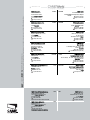
TECHNICAL FEATURES
power supply 230V - 50/60Hz
max power 600W
max power of 24V accessories 20W
insulation rating
casing material ABS
casing protection rating IP54
operating temperature -20 / +55°C

F U SI B I LI LIN EA 5 A
QUADRO C OMANDO
ZA4
FUSIBILE CEN TRALINA 1A
T. L.
T. C . A .
TR2M .
1 2
L1 L2 UVWXYE1 10 11 1 5 7 C1
23
L1 L2 C 24120
L2T L1T1234
012 24
1
48
2
3
9
10 5 6 7
11
Pag.
3
3 - Manual code:
319V08
319V08 ver.
1.0
1.0 05/2009 © CAME cancelli automatici s.p.a. - The data and information reported in this installation manual are susceptible to change at any time and without obligation on CAME cancelli automatici s.p.a. to notify users.
ENGLISH
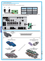
4.1 Main components
Warning! Before acting on the machinery,
cut off the main power supply.
1 - Connection terminal boards
2 - Line fuse 5A
3 - Control unit fuse 1A
4 - Radio-code save buttons
5 - Trimmer TL: Operating time adjustment
6 - Trimmer delay on closing cycle motor n°2
adjustment
7 - Trimmer TCA: Automatic closing time
adjustment
8 - 2-dip function switch (see pag.6)
9 - Socket AF radiofrequency board (see table)
10 - Signaling LED
11 - Motor torque regulator
Before installing, do the following:
• Check that the panel’s anchoring point is protected from possible blows, and that the anchoring surface is solid. Also check that the
anchoring is done using the appropriate bolts, screws etc.
• Make sure you have a suitable omnipolar cut-off device with contacts more than 3 mm apart, and independent (sectioned off) power
supply.
• Make sure that any connections inside the case (that provide continuance to the protective circuit) be fitted with extra insulation
as compared to the other conductive parts inside.
• Make sure you have suitable tubing and conduits for the electrical cables to pass through and be protected against mechanical
damage.
Make sure you have all the tools and materials you will need for the installation at hand to work in total safety and compliance with the
current standards and regulations.
5 Installation
5.1 Preliminary checks
5.2 Tools and materials
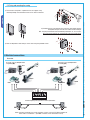
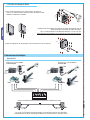
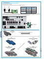
N.B. FROG series: connect the black wires coming
out of the board to the connectors of the fi rst motor’s
condenser and the red wires to the second motor’s
condenser.

UVWXYE1
FROG
FERNI
KRONO
FROG
FERNI
KRONO
FAST
ATI
ATI
M1 M2
FAST
Pag.
4
4 - Manual code:
319V08
319V08 ver.
1.0
1.0 05/2009 © CAME cancelli automatici s.p.a. - The data and information reported in this installation manual are susceptible to change at any time and without obligation on CAME cancelli automatici s.p.a. to notify users.
ENGLISH
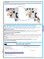
6 Electrical connections
When using only one motor (e.g. on one leaf gates), connect it up on W X Y (M2) regardless of
which side it is installed on – (fro FROG, if need be, invert connections X and Y).
Standard opening setup scheme in Came gearmotors.
Gearmotor featuring delayed action
on opening (M1)
Gearmotor featuring delayed action
on closing (M2)
Gearmotor
1) Fix the base of the panel in a protected area; we suggest using
round top Phillips recessed head screws of max. 6mm in diameter.
5.3 Fixing and mounting the casing
2) Perforate the pre-punched holes and insert the cable glands with the
corrugated tubing for the electrical cables to travel through.
N.B.: the pre-punched holes have the following diameters: 23, 29 e 37 mm.
Be careful not to damage the control board inside the control panel!!
3) After the adjustments and settings, fix the cover using the provided screws.

10 11 1 5 7 C1
23
L1 L2 UVWXYE1 10 11 1 5 7 C1
23
10 11L1 L2
Pag.
5
5 - Manual code:
319V08
319V08 ver.
1.0
1.0 05/2009 © CAME cancelli automatici s.p.a. - The data and information reported in this installation manual are susceptible to change at any time and without obligation on CAME cancelli automatici s.p.a. to notify users.
ENGLISH
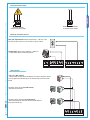
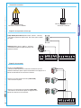
Accessories power supply
230V A.C. 50/60 Hz
control panel power supply
Terminal board for 24V A.C.
accessories power supply
Signalling and lighting devices
Open gate light-indicator (Socket rating: 24V A.C. - 3W max.). Turns
on when the gate is open. It turns off when the gate is closed.
Flashing light (Socket rating: 230V A.C. - 25W max.)
- Flashes during opening and closing phases.
Control devices
Stop button ( N.C. contact)
- Button to stop the gate which immediately cuts-out the automatic closing
cycle; to restore the movement press the control button or the transmitter
button.
Keyswitch and/or open button (N.O. contact)
- Gate opening command.
Keyswitch and/or comand button (N.O. contact)
- Gate opening/closing command. By pressing the button or
turning the selector key.

FUSIBILI LINEA 5A
QUADR O CO MAN DO
ZA4
FUSIBILE CENTRALINA 1 A
T. L.
T. C . A .
TR2M.
1 2
L1 L2 UVWXYE1 10 11 1 5 7 C1
23
L1 L2 C 24120
10 11 1 5 7 C1
23
TX
./ # .#
RX
ON
OFF
1 2
10 11 1 5 7 C1
23
TXRX
Pag.
6
6 - Manual code:
319V08
319V08 ver.
1.0
1.0 05/2009 © CAME cancelli automatici s.p.a. - The data and information reported in this installation manual are susceptible to change at any time and without obligation on CAME cancelli automatici s.p.a. to notify users.
ENGLISH
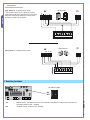
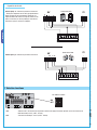
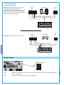
(N.C.) contact for «re-opening during closing»
DOC photocells
7 Selecting functions
DIP-SWITCH 2 WAYS
1 ON Operator present”, gate operates only when the pushbutton is held down (the radio remote control system is
deactivated) enabled; (1 OFF - disabled);
2 ON “Automatic closing” enabled; (2 OFF - disabled).
Safety devices
(N.C.) contact for «re-opening during closing»
- Input for safety devices such as photocells, sensitive
edges and other EN 12978-compliant devices. During the
gate leaves closing phase, opening the contact causes
movement inversion until fully opened.
DIR photocells

FUSIBILI LINEA 5A
QUADR O CO MAN DO
ZA4
FUSIBILE CENTRALINA 1 A
T. L.
T. C . A .
TR2M.
1 2
L1 L2 UVWXYE1 10 11 1 5 7 C1
23
L1 L2 C 24120
T. L.
T. C . A .
TR2M.
1234
L2T
L1T
0
24
12
L1T L2T CT
01224
FUS IBI LI LIN EA 5A
QUADRO COMANDO
ZA4
FUSIBILE CEN TRALINA 1 A
T.L .
T.C . A.
TR2M.
1 2
1234
L2T
L1T
0
24
12
L1TL2T CT
01224
Pag.
7
7 - Manual code:
319V08
319V08 ver.
1.0
1.0 05/2009 © CAME cancelli automatici s.p.a. - The data and information reported in this installation manual are susceptible to change at any time and without obligation on CAME cancelli automatici s.p.a. to notify users.
ENGLISH
8 Adjustments
Trimmer T.L. = Adjusting the working time from 5” to 50”.
Trimmer TR2M = Closing delay regulation for the 2nd motor (M2) from a minimum of 1” to a maximum of 10”.
Trimmer T.C.A. = Adjusting the automatic closing from 3” to 130”.
9 Motor torque limiter
To vary the motor torque, shift the shown faston to one of the 4 positions: 1 min., 4 max.
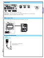
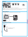
10 Activating the radio control
Connect the antenna’s RG58 cable to
the apposite terminals.
Antenna

CAME
CAME
TOP
TOP-432A • TOP-434A
TAM
T432 • T434 • T438
TAM-432SA
CAME
CAME
CAME
ATOMO
AT01 • AT02
AT04
CAME
CAME
CAME
CAME
CAME
CAME
CAME
CAME
CAME
TFM
T132 • T134 • T138
T152 • T154 • T158
TOP
TOP-432NA • TOP-434NA
TOP-432S
FUSIBILI LINEA 5A
QUAD RO C OM AN DO
ZA4
FUSIBILE CENTRALINA 1 A
T. L.
T. C . A .
TR2M .
1 2
L1 L2 UVWXYE1 10 11 1 5 7 C1
23
L1 L2 C 24120
TOP TAM
Pag.
8
8 - Manual code:
319V08
319V08 ver.
1.0
1.0 05/2009 © CAME cancelli automatici s.p.a. - The data and information reported in this installation manual are susceptible to change at any time and without obligation on CAME cancelli automatici s.p.a. to notify users.
ENGLISH
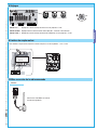
Transmitters
see attached instructions
see instructions attached to
AF43SR card
AF card
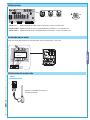
Lock the radiofrequency card into the electronic card AFTER CUTTING OFF THE POWER SUPPLY (or after disconnecting the batteries).
N.B.: The control board only recognises the radiofrequency card when the power is on.
Radio frequency card
Only for cards marked on the table:
- place the jumper as shown depending on the series of transmitters used. (see diagram).
Frequency/Mhz Radio
frequency card
Transmitters
series
FM 26.995 AF130 TFM
FM 30.900 AF150 TFM
AM 433.92 AF43S/AF43SM TAM/TOP
AF43SR ATOMO

11 Phasing out and disposal
12 Conformity declaration
Also, they furthermore represent and warrant that the product/s that are the subject
of the present Declaration are manufactured in the respect of the following main
Reference code to request a true copy of the original: DDC L EN Z002
MANUFACTURER’S DECLARATION
As per Enclosure II A of Directive 2006/95/CE
The representatives of
CAME Cancelli Automatici S.p.A.
via Martiri della Libertà, 15
31030 Dosson di Casier - Treviso - ITALY
tel (+39) 0422 4940 - fax (+39) 0422 4941
internet: www.came.it - e-mail: [email protected]
Hereby declare, under their own respons ibility, that the product/s called ...
… complies with the provisions of the following Directives
2006/95/CE - Direttiva Bassa Tensione
2004/108/CE - Direttiva Compatigilità Elettromagnetica
EN 60335-1 / EN 60335-2-103 / EN 13241-1 / EN 61000-6-2 / EN 61000-6-3
Managing Director
Mr. Gianni Michielan
ZA4N
harmonized provisions:
T. L.
T. C . A .
TR2M.
1 2
PROG
T. L .
T.C.A.
TR2M.
1 2
PROG
Pag.
9
9 - Manual code:
319V08
319V08 ver.
1.0
1.0 05/2009 © CAME cancelli automatici s.p.a. - The data and information reported in this installation manual are susceptible to change at any time and without obligation on CAME cancelli automatici s.p.a. to notify users.
ENGLISH
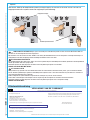
Memorisation
Intermitting LED
AF radio frequency card
In its premises, CAME CANCELLI AUTOMATICI S.p.A. implements an Environmental Management System certified in
compliance with the UNI EN ISO 14001 standard to ensure environmental protection.
Please continue our efforts to protect the environment—which CAME considers one of the cardinal elements in the development of its
operational and market strategies—simply by observing brief recommendations as regards disposal:
DISPOSAL OF PACKAGING
The packaging components (cardboard, plastic, etc.) are all classifiable as solid urban waste products and may be disposed of easily,
keeping in mind recycling possibilities.
Prior to disposal, it is always advisable to check specific regulations in force in the place of installation.
PLEASE DISPOSE OF PROPERLY!
PRODUCT DISPOSAL
Our products are made up of various types of materials. Most of them (aluminium, plastics, iron, electrical wires, etc.) may be disposed
of in normal garbage collection bins and can be recycled by disposing of in specific recyclable material collection bins and disposal in
authorized centres. Other components (electrical boards, remote control batteries, etc.), however, may contain polluting substances.
They should therefore be removed and given to qualified service companies for proper disposal.
Prior to disposal, it is always advisable to check specific regulations in force in the place of disposal.
PLEASE DISPOSE OF PROPERLY!
Keep the “PROG” button pressed on the base board (the signal led will fl ash), the code is sent by a transmitter button and the led
remains alight to signal that it has been stored (see the fi gure).

CAME
CAME
France
France
S.a.
S.a. FRANCE
7, Rue Des Haras
Z.i. Des Hautes Patures
92737
Nanterre Cedex
Nanterre Cedex
(+33) 1 46 13 05 05
(+33) 1 46 13 05 00
GERMANY
CAME Gmbh
CAME Gmbh
Kornwestheimer Str. 37
70825
Korntal
Korntal Munchingen Bei Stuttgart
(+49) 71 5037830
(+49) 71 50378383
CAME Automatismes S.a.
CAME Automatismes S.a. FRANCE
3, Rue Odette Jasse
13015
Marseille
Marseille
(+33) 4 95 06 33 70
(+33) 4 91 60 69 05
GERMANY
CAME Gmbh Seefeld
CAME Gmbh Seefeld
Akazienstrasse, 9
16356
Seefeld
Seefeld Bei Berlin
(+49) 33 3988390
(+49) 33 39883985
CAME Automatismos S.a.
CAME Automatismos S.a. SPAIN
C/juan De Mariana, N. 17-local
28045
Madrid
Madrid
(+34) 91 52 85 009
(+34) 91 46 85 442
U.A.E.
CAME Gulf Fze
CAME Gulf Fze
Offi ce No: S10122a2o210
P.O. Box 262853
Jebel Ali Free Zone -
Dubai
Dubai
(+971) 4 8860046
(+971) 4 8860048
CAME United Kingdom Ltd.
CAME United Kingdom Ltd. GREAT BRITAIN
Unit 3 Orchard Business Park
Town Street, Sandiacre
Nottingham
Nottingham - Ng10 5du
(+44) 115 9210430
(+44) 115 9210431
RUSSIA
CAME Russia
CAME Russia
Umc Rus Llc
Umc Rus Llc
Ul. Otradnaya D. 2b, Str. 2, offi ce 219
127273,
Moscow
Moscow
(+7) 495 739 00 69
(+7) 495 739 00 69 (ext. 226)
CAME Group Benelux S.a.
CAME Group Benelux S.a. BELGIUM
Zoning Ouest 7
7860
Lessines
Lessines
(+32) 68 333014
(+32) 68 338019
CHINA
CAME (Shanghai)
CAME (Shanghai)
Automatic Gates Co. Ltd.
Automatic Gates Co. Ltd.
1st Floor, Bldg 2, No. 1755, South Hongmei Road
Shanghai
Shanghai 200237
(+86) 021 61255005
(+86) 021 61255007
CAME Americas Automation Llc
CAME Americas Automation Llc U.S.A
11405 NW 122nd St.
Medley
Medley, FL 33178
(+1) 305 433 3307
(+1) 305 396 3331
PORTUGAL
CAME Portugal
CAME Portugal
Ucj Portugal Unipessoal Lda
Ucj Portugal Unipessoal Lda
Rua Jùlio Dinis, N. 825, 2esq
4050 327
Porto
Porto
(+351) 915 371 396
CAME Cancelli Automatici S.p.a.
CAME Cancelli Automatici S.p.a. ITALY
Via Martiri Della Libertà, 15
31030
Dosson Di Casier
Dosson Di Casier (Tv)
(+39) 0422 4940
(+39) 0422 4941
Informazioni Commerciali 800 848095
ITALY
CAME Sud s.r.l.
CAME Sud s.r.l.
Via F. Imparato, 198
Centro Mercato 2, Lotto A/7
80146
Napoli
Napoli
(+39) 081 7524455
(+39) 081 7529190
CAME Service Italia S.r.l.
CAME Service Italia S.r.l. ITALY
Via Della Pace, 28
31030
Dosson Di Casier
Dosson Di Casier (Tv)
(+39) 0422 383532
(+39) 0422 490044
Assistenza Tecnica 800 295830
Assistenza Tecnica 800 295830
08_2009
www.came.com www.came.it
English
English - Manual code:
319V08
319V08 ver.
1.0
1.0 05/2009 © CAME cancelli automatici s.p.a.
The data and information reported in this installation manual are susceptible to change at any time and without obligation on CAME cancelli automatici s.p.a. to notify users.
Seite wird geladen ...
Seite wird geladen ...
Seite wird geladen ...
Seite wird geladen ...
Seite wird geladen ...
Seite wird geladen ...
Seite wird geladen ...
Seite wird geladen ...
Seite wird geladen ...
Seite wird geladen ...
Seite wird geladen ...
Seite wird geladen ...
Seite wird geladen ...
Seite wird geladen ...
Seite wird geladen ...
Seite wird geladen ...
Seite wird geladen ...
Seite wird geladen ...
Seite wird geladen ...
Seite wird geladen ...
Seite wird geladen ...
Seite wird geladen ...
Seite wird geladen ...
Seite wird geladen ...
Seite wird geladen ...
Seite wird geladen ...
Seite wird geladen ...
Seite wird geladen ...
Seite wird geladen ...
Seite wird geladen ...
Seite wird geladen ...
Seite wird geladen ...
Seite wird geladen ...
Seite wird geladen ...
Seite wird geladen ...
Seite wird geladen ...
Seite wird geladen ...
Seite wird geladen ...
Seite wird geladen ...
Seite wird geladen ...
-
 1
1
-
 2
2
-
 3
3
-
 4
4
-
 5
5
-
 6
6
-
 7
7
-
 8
8
-
 9
9
-
 10
10
-
 11
11
-
 12
12
-
 13
13
-
 14
14
-
 15
15
-
 16
16
-
 17
17
-
 18
18
-
 19
19
-
 20
20
-
 21
21
-
 22
22
-
 23
23
-
 24
24
-
 25
25
-
 26
26
-
 27
27
-
 28
28
-
 29
29
-
 30
30
-
 31
31
-
 32
32
-
 33
33
-
 34
34
-
 35
35
-
 36
36
-
 37
37
-
 38
38
-
 39
39
-
 40
40
-
 41
41
-
 42
42
-
 43
43
-
 44
44
-
 45
45
-
 46
46
-
 47
47
-
 48
48
-
 49
49
-
 50
50
-
 51
51
-
 52
52
-
 53
53
-
 54
54
-
 55
55
-
 56
56
-
 57
57
-
 58
58
-
 59
59
-
 60
60


in anderen Sprachen
- English: CAME 309ZA4110NI Installation guide
- français: CAME 309ZA4110NI Guide d'installation
- italiano: CAME 309ZA4110NI Guida d'installazione
- Nederlands: CAME 309ZA4110NI Installatie gids
- português: CAME 309ZA4110NI Guia de instalação
Verwandte Artikel
-
CAME Twister Spare Parts Manual
-
CAME Z24-Z230 Spare Parts Manual
-
-
CAME ZA4 Benutzerhandbuch
-
-
-
-
-
-
